Advertisement
Table of Contents
- 1 Safety Precautions
- 2 Operation
- 3 Operating Environment
- 4 Installing the Inverter
- 5 Names and Functions of Keypad Components
- 6 If an Alarm Code Appears on the LED Monitor
- 7 Specifications
- 8 Three-Phase 400 V Class Series
- 9 Connection Diagram in Operation by External Signal Inputs
- 10 Function Code Tables
- 11 F Codes: Fundamental Functions
- 12 Conformity with UL Standards and Cul-Listed for Canada
- 13 Product Warranty
- Download this manual
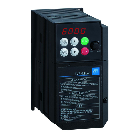
Advanced simple Inverter
Thank you for purchasing our FVR-Micro of inverters.
This product is designed to drive a three-phase induction motor. Read through this
instruction manual and be familiar with the handling procedure for correct use.
Improper handling might result in incorrect operation, a short life, or even a failure of this
product as well as the motor.
Deliver this quick guide to the end user of this product. Keep this in a safe place until this
product is discarded.
For more details, refer to the instruction manual on website.
Web site :
https://felib.fujielectric.co.jp/download/search.htm?site=global&lang=en
QR code :
Fuji Electric Co., Ltd.
FVR-Micro
Brief Manual
INR-SI47-2142a-E
Advertisement
Table of Contents


Need help?
Do you have a question about the FVR0.75AS1S-4 and is the answer not in the manual?
Questions and answers