Viconics VT8600 Series Installation Manual
Rooftop unit, heat pump and indoor air quality controller
Hide thumbs
Also See for VT8600 Series:
- Installation manual (11 pages) ,
- User interface manual (96 pages)

Related Manuals for Viconics VT8600 Series


Summary of Contents for Viconics VT8600 Series
-
Page 1: Table Of Contents
VT8600 Series Installation Guide Rooftop Unit, Heat Pump and Indoor Air Quality Controller CONTENTS Installation Terminal Identification & Function Terminal identification Typical Applications Remote Sensor Accessories Home Screen Display How to Enter Setup Screen Appendix... -
Page 2: Installation
• A short circuit or wrong wiring may permanently damage Controller or equipment. • All VT8600 series controls are designed for use as operating controls only and are not safety devices. Tampering with the devices or unintended application of the devices will result in a void of warranty. -
Page 3: Terminal Identification & Function
Installation Guide VT8600 Series TERMINAL IDENTIFICATION & FUNCTION Terminal identification VT86xxU Used in applications Description / Application IAQ, HP & RTU Internal Temperature 1- BO1 2- BO2 3- BO3 4- BO4 5- RC RC (24 Vac) 6- C Common 7- RH... -
Page 4: Typical Applications
Installation Guide VT8600 Series TYPICAL APPLICATIONS VT8600 RTU: 2 Heating Stages / 2 Cooling Stages AIR FLOW MEASURING STATION (0-10 VDC) 1 2 3 4 5 6 7 8 9 10 11 12 TRANSMITTER (0-10 VDC) ECONO FILTER SENSOR SENSOR... - Page 5 Installation Guide VT8600 Series VT8600 RTU: 2 Cooling Stages / Modulating Heat AIR FLOW MEASURING STATION (0-10 VDC) 1 2 3 4 5 6 7 8 9 10 11 12 Mod. Heat TRANSMITTER (0-10 VDC) (0-10 VDC) ECONO FILTER SENSOR...
- Page 6 Installation Guide VT8600 Series VT8600 HPU: 2 Compressors, Auxiliary Heat and Economizer AIR FLOW MEASURING STATION (0-10 VDC) 1 2 3 4 5 6 7 8 9 10 11 12 TRANSMITTER (0-10 VDC) ECONO FILTER SENSOR SENSOR 13 14 15 16 17 18 19 20 21 22 23 24 Viconics Technologies Inc.
-
Page 7: Remote Sensor Accessories
Installation Guide VT8600 Series REMOTE SENSOR ACCESSORIES Model Number Description S3010W1000 Wall mounted temperature sensor S3020W1000 Wall mounted temperature sensor with override button and occupancy status LED Note: If one or multiple sensor(s) is/are connected into the RS terminal, the internal temperature sensor is automatically disabled. Dis- connecting the sensor(s) in RS terminal will re-activate the internal sensor. -
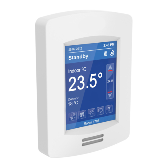
Page 8: Home Screen Display
Installation Guide VT8600 Series HOME SCREEN DISPLAY Typical Hospitality User Interface Shown Time Date System Status Occupancy Status Fan Status Up Arrow Increase Temperature Setpoint Indoor Temperature Actual Setpoint Down Arrow Outdoor Temperature Decrease Temperature Setpoint Help System Mode Short Network... -
Page 9: How To Enter Setup Screen
Touch and hold this point For more information on using and configuring the functions of the HMI, for 3 seconds to enter set-up mode refer to the VT8600 Series User Interface Guide Note: If a configuration/installer password is activated to prevent... -
Page 10: Appendix
VT7000 series Room Controllers. There is a direct correspondance of functions between the terminals of the VT7000 series and the VT8600 series. Consult the table below to verify the appropriate terminal when replacing a VT7000 Room Controller with a VT8600 Room Controller.
Need help?
Do you have a question about the VT8600 Series and is the answer not in the manual?
Questions and answers