Table of Contents
Advertisement
THIS MANUAL CONTAINS IMPORTANT SAFETY INFORMATION AND SHOULD ALWAYS BE
AVAILABLE TO THOSE PERSONNEL OPERATING THIS UNIT.
READ, UNDERSTAND AND RETAIN ALL INSTRUCTIONS BEFORE OPERATING THIS
EQUIPMENT TO PREVENT INJURY OR EQUIPMENT DAMAGE.
MODEL R70A COMPRESSOR
Form No. F3234
VER: 09 07/01/2009
TWO STAGE/FOUR CYLINDER R70A
AIR COMPRESSOR & UNITS
WARNING
C324-A
(Ref. Drawing)
OPERATION/MAINTENANCE
MANUAL & PARTS LIST
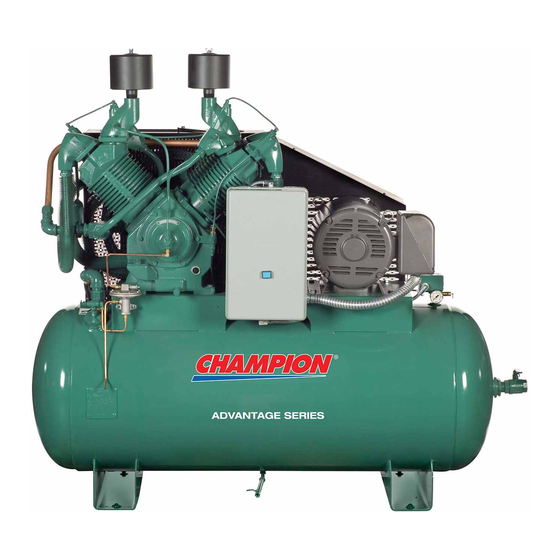
MODEL HRA25-12 UNIT
C469-A
(Ref. Drawing)
Advertisement
Table of Contents

Subscribe to Our Youtube Channel
Related Manuals for Champion HRA20-12


Summary of Contents for Champion HRA20-12
- Page 1 OPERATION/MAINTENANCE MANUAL & PARTS LIST TWO STAGE/FOUR CYLINDER R70A AIR COMPRESSOR & UNITS WARNING THIS MANUAL CONTAINS IMPORTANT SAFETY INFORMATION AND SHOULD ALWAYS BE AVAILABLE TO THOSE PERSONNEL OPERATING THIS UNIT. READ, UNDERSTAND AND RETAIN ALL INSTRUCTIONS BEFORE OPERATING THIS EQUIPMENT TO PREVENT INJURY OR EQUIPMENT DAMAGE.
-
Page 2: Maintain Compressor Reliability And Performance With
They are ready to respond and assist you by providing fast, expert maintenance and repair services. For the location of your local authorized Champion Air Compressor distributor, refer to the yellow pages of your phone directory or contact: Factory:... -
Page 3: Table Of Contents
TABLE OF CONTENTS _______________________________________________________ Subject Page Maintain Compressor Reliability And Performance With ..............2 Safety And Operation Precautions......................4 Explanation Of Safety Instruction Symbols And Decals ............... 5 Introduction ............................6 Warranty..............................6 Dimensions And Specifications......................7 Installation ..........................8, 9 & 10 Operation............................. -
Page 4: Safety And Operation Precautions
Safety and Operation Precautions can result in injuries or equipment damage. However, Champion does not state as fact or does not mean to imply that the preceding list of Safety and Operating Precautions is all inclusive, and further that the observance of this list will prevent all injuries or... -
Page 5: Explanation Of Safety Instruction Symbols And Decals
WARNING Indicates hazards or unsafe practice which could result in severe injury or death. CAUTION Indicates hazards or unsafe practice which could result in damage to the Champion compressor or minor injury. NOTICE Notice is used to notify people of installation, operation or maintenance information which is important but not hazard-related. -
Page 6: Introduction
Applies to CHAMPION logo, tank or base mounted complete compressors only. Express Limited Warranty CHAMPION warrants each new air compressor unit manufactured by CHAMPION to be free from defects in material and workmanship under normal use and service for a period of twelve (12) months from date of installation or eighteen (18) months from date of shipment by CHAMPION or CHAMPION distributor, whichever may occur first. -
Page 7: Dimensions And Specifications
TWO STAGE AIR COMPRESSORS - MODEL R70A DIMENSIONS ITEM PL70A Base-Width 12-7/8” Bolt Down-Width 5-11/16” (from center line) Bolt Down to Edge 3/4” Base to Crank Ctr 8-3/16” Overall Width 33” Overall Height 33-9/16” HP Exhaust Opening 1-1/4NPT Bolt Down Hole Dia. 9/16”... -
Page 8: Installation
It is recommended that unit be set on optional vibro-isolator pads. Tanks bolted directly to a concrete floor without isolators will not be warranted against cracking. Champion vibro-isolators or approved equivalent must be installed for extended warranty to apply to ASME receivers. - Page 9 INSTALLATION (CONT’D) ELECTRICAL POWER SUPPLY It is essential that the power supply and the supply wiring are adequately sized and that the voltage correspond to the unit specifications. Branch circuit protection must be provided at installation a specified in the National Electrical Code. All wiring should be performed by a licensed electrician or electrical contractor.
- Page 10 ELECTRICAL POWER SUPPLY (CONT’D) 312CAD546-B (Ref. Drawing) Figure 1-2 Duplex Wiring Diagram CAUTION Wiring must be such that when viewing compressor from opposite shaft end, rotation of shaft is clockwise as shown by arrow on guard. Wrong direction rotation for any length of time will result in damage to compressor.
-
Page 11: Operation
OPERATION This compressor has been inspected, thoroughly tested and approved at the factory. For this unit to give long satisfactory service it must be installed and operated properly. This compressor has been designed for a 80%/ON – 20%/OFF duty cycle. Simplex units have a pressure switch that senses changes in receiver pressure and automatically starts and stops the compressor at preset pressure limits. -
Page 12: Maintenance
GUIDE TO MAINTENANCE For Service contact an authorized Champion distributor. All requests should include model number and serial number. To obtain reliable and satisfactory service, this unit requires a consistent preventive maintenance schedule. Maintenance schedule form is included to aid in keeping the proper records. - Page 13 EVERY 90 DAYS OR 500 HOURS MAINTENANCE Change crankcase oil. Use only Champlub recip lubricant. Check entire system for air leakage around fittings, connections, and gaskets, using soap solution and brush. Tighten nuts and cap screws as required. Check and clean compressor valves as required. Replace when worn or damaged parts. CAUTION Valves must be replaced in original position.
- Page 14 GENERAL MAINTENANCE (Cont'd.) CENTRIFUGAL UNLOADER AND UNLOADER PRESSURE RELEASE VALVE: The centrifugal unloader is operated by two governor weights. It is totally enclosed and lubricated from the crankcase of the compressor. When compressor starts, the governor weights automatically open compressing the main spring, allowing the unloader pressure release valve to close. When the compressor stops, the main spring returns the governor weights to normal position opening the unloader pressure release valve and unloading the compressor.
-
Page 15: Compressor Pilot Valve Differential Pressure Adjustment
COMPRESSOR PILOT VALVE PRESSURE ADJUSTMENT Proceed with the following instructions while compressor is running: Loosen locknut (4) and back off several turns. Do not turn differential pressure adjustment nut (3). Check reading on the tank pressure gauge. Set the compressor maximum pressure by turning threaded cap (1) clockwise to increase pressure or counter clockwise to decrease pressure. -
Page 16: Compressor Oil Specifications
“Emulsification of oil (white milky substance) indicates unsafe accumulation of moisture and may be evidence compressor is oversized for application. Failure to promptly consult your local distributor, or Champion Customer Service, can be grounds to deny warranty.” NOTES: 1. Normal break-in period of Champion air compressors is 25 hours. -
Page 17: Trouble Shooting Guide
TROUBLE SHOOTING CHART FOR COMPRESSOR WARNING Always disconnect unit from power supply and relieve all pressure from air tank before performing any maintenance. “Tag Out” or “Lock Out” all power sources. Failure to do so may result in equipment damage or injury. Never operate unit without belt guard in place. - Page 18 Troubleshooting Chart (cont’d) Symptom Possible Cause(s) Corrective Action Air escapes from centrifugal unloader Centrifugal unloader release valve Clean or replace valve. when unit is running. dirty or defective. Air escapes from centrifugal unloader Check valve stuck in open position. Replace check valve. when unit is stopped.
- Page 19 UNIT REPAIR PARTS ILLUSTRATION MODELS: HRA20-12, HRA20-25, HRA25-12, HRA25-25, HRA30-12, & HRA30-25 13 (NOTSHOWN) 12 (NOT SHOWN) A.S.M.E. DATA PLATE C466-A (Ref. Drawing) REPAIR PARTS LIST MODEL HRA20-12 HRA20-25 HRA25-12 HRA25-25 HRA30-12 HRA30-25 Pump R70A R70A R70A R70A R70A R70A...
- Page 20 UNIT REPAIR PARTS ILLUSTRATION MODELS: BRA-20, BRA-25, & BRA-30 6 (NOT SHOWN) 5 (NOT SHOWN) C467-A (Ref. Drawing) REPAIR PARTS LIST MODEL BRA-20 BRA-25 BRA-30 Pump R70A R70A R70A Belt Guard Z674 Z674 Z674 Base Plate P03538C P03538C P03538C Motor 20 HP 25 HP 30 HP...
-
Page 21: Unit Repair Parts List
UNIT REPAIR PARTS ILLUSTRATION MODELS: HRA20D-25, HRA25D-25, & HRA30D-25 12, 13 (NOT SHOWN) A.S.M.E. DATA PLATE C468-A (Ref. Drawing) REPAIR PARTS LIST MODEL HRA20D-25 HRA25D-25 HRA30D-25 Pump R70A R70A R70A Pressure Gauge M519C M519C M519C Belt Guard Z674 Z674 Z674 Drain Valve VP1022988 VP1022988... - Page 22 COMPRESSOR REPAIR PARTS ILLUSTRATION Models: R70A C308-B (Ref. Drawing)
- Page 23 Repair Parts List Compressor Model R70A Ref. Part Description Qty. Number Crankcase M1386 Pipe plug 64AA5 Oil level gauge RE714 Pipe nipple M492 Pipe cap M461 Pipe plug 64A5 Crankshaft M1387 Main bearing Z6506 Oil seal P03433A Governor housing gasket set Z775 Governor housing P12274C...
- Page 24 Repair Parts List Compressor Model R70A Ref. Part Description Qty. Number Cylinder P05863D Hex head cap screw M3461 Low pressure intake valve assembly Z273 Low pressure valve gasket P07352A Low pressure discharge valve assembly Z274 High pressure discharge valve assembly Z785 High pressure valve gasket P07353A...
-
Page 25: Compressor Repair Parts List
COMPRESSOR REPAIR PARTS ILLUSTRATION Model: R70A TUBE ASSEMBLIES C470-B (Ref. Drawing) Repair Parts List Models R70A Ref. No. Description Part Number Qty. Breather tube (includes compression fittings) ZM1420 3/8 x 1/4 NPT straight compression fittings M2864 Release valve tube (includes compression fittings) ZM1421 1/4 x 1/8 NPT straight compression fitting M2863... -
Page 26: Constant Speed Head Unloader
CONSTANT SPEED HEAD UNLOADER FOR AIR COMPRESSOR MODEL R70A NOTE: This is optional equipment and may not be included on your unit. It is recommended constant speed unloading be used if motor starts exceed 6 starts/hour. The purpose of constant speed unloading is to provide a means of stopping or starting the compression of air by the compressor without stopping or starting the electric motor or gasoline engine after each cycle. -
Page 27: Unit Hazard Decal Listing
UNIT HAZARD DECAL LISTING PAGE DESCRIPTION PART NO. PRODUCT LIABILITY DECAL SHEET - MASTER P10157A Unit Pressure Setting NOT USED DANGER – Breathing Air DANGER – Drain Tank Daily WARNING – Pressure/Safety Valve NOT USED DANGER – Valve Maintenance DANGER – High Voltage WARNING –... -
Page 28: Unit Hazard Decals
UNIT HAZARD DECALS... - Page 29 PUMP HAZARD DECALS...
-
Page 30: Record Of Maintenance Service
RECORD OF MAINTENANCE SERVICE Daily • DRAIN MOISTURE FROM TANK WEEKLY EVERY 3 MONTHS • CLEAN FILTER • INSPECT VALVE ASSEMBLIES • CLEAN COMPRESSOR •TIGHTEN ALL FASTENERS • CHECK V-BELTS •TEST PRESSURE RELIEF VALVE... - Page 31 RECORD OF MAINTENANCE SERVICE Daily • DRAIN MOISTURE FROM TANK WEEKLY EVERY 3 MONTHS • CLEAN FILTER • INSPECT VALVE ASSEMBLIES • CLEAN COMPRESSOR •TIGHTEN ALL FASTENERS • CHECK V-BELTS •TEST PRESSURE RELIEF VALVE...
- Page 32 Phone (815) 875-3321 Fax (815) 872-0421 E-mail: champion@championpneumatic.com Copyright © 2009 Gardner Denver, Inc. Plants in Princeton, IL, and Manteca, CA Printed in U.S.A. Due to Champion’s continuing product development program, specifications and materials are subject to change without notice or obligation...
Need help?
Do you have a question about the HRA20-12 and is the answer not in the manual?
Questions and answers