Table of Contents
Advertisement
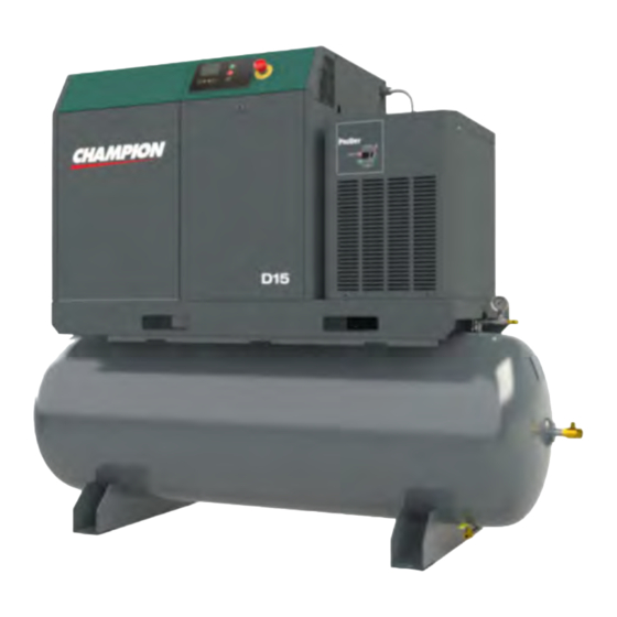
D10 (TD)
D15 (TD)
DRS 15 (TD)
Rotary Screw
Air Compressor
Units
- - -
Installation
And
Start-up Data
Authorized distributor service technicians are factory trained and skilled in compressor maintenance
and repair. They are ready to respond and assist you by providing fast, expert maintenance and repair
services.
Contents:
Quick Start ............................................................
Safety Precautions ...........................................
Unpacking And Inspection ..................................
Installation – Mechanical ...................................
Lubrication .....................................................
Installation – Electrical ......................................
Motor Maintenance Instructions ............................
Start-Up Procedures .........................................
Preventative Maintenance Schedule ....................
Maintenance Procedures ......................................
'CSC300' Controller ............................................... 21
Common Compressor Faults ...............................
Variable Speed Drive ........................................... 31
Separator Filter & Refrigerated Air Dryer ............... 37
Trouble-Shooting Guide ...................................... 40
Warranty ......................................................... 43
Please read this manual before
Compressor Unit. It contains
valuable information that will
Please keep this manual in a
safe place for future reference.
procedures in this reference manual apply
- 1 -
D10.D15.DRS15-MANS
installing or using your Air
help in the receiving,
installation, use, and
maintenance of the Unit.
All of the information, policies, and
exclusively to Champion.
Apr '19
Page:
2
4
5
6
8
9
11
12
13
15
30
Advertisement
Table of Contents


Need help?
Do you have a question about the D15 and is the answer not in the manual?
Questions and answers