Champion R30D Operation Maintenance Manual & Parts List

Champion R30D Operation Maintenance Manual & Parts List

Two stage/four cylinder air compressors & units

Advertisement

TWO STAGE/FOUR CYLINDER AIR COMPRESSORS & UNITS
THIS MANUAL CONTAINS IMPORTANT SAFETY INFORMATION AND SHOULD ALWAYS BE
AVAILABLE TO THOSE PERSONNEL OPERATING THIS UNIT.
READ, UNDERSTAND AND RETAIN ALL INSTRUCTIONS BEFORE OPERATING THIS
EQUIPMENT TO PREVENT INJURY OR EQUIPMENT DAMAGE.
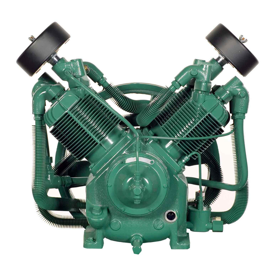
MODEL R30D COMPRESSOR
Form No. F3233
Ver: 11
FEATURING THE R30D PUMP
C408-A
(Ref. Drawing)
07/01/2009
OPERATION/MAINTENANCE
MANUAL & PARTS LIST
MODEL HR10-12 UNIT
C476-A
(Ref. Drawing)

Advertisement

Table of Contents
loading

Summary of Contents for Champion R30D

  • Page 1 OPERATION/MAINTENANCE MANUAL & PARTS LIST TWO STAGE/FOUR CYLINDER AIR COMPRESSORS & UNITS FEATURING THE R30D PUMP THIS MANUAL CONTAINS IMPORTANT SAFETY INFORMATION AND SHOULD ALWAYS BE AVAILABLE TO THOSE PERSONNEL OPERATING THIS UNIT. READ, UNDERSTAND AND RETAIN ALL INSTRUCTIONS BEFORE OPERATING THIS EQUIPMENT TO PREVENT INJURY OR EQUIPMENT DAMAGE.
  • Page 2 They are ready to respond and assist you by providing fast, expert maintenance and repair services. For the location of your local authorized Champion Air Compressor distributor, refer to the yellow pages of your phone directory or contact: Factory:...
  • Page 3: Table Of Contents

    TABLE OF CONTENTS _______________________________________________________ Subject Page Safety And Operation Precautions..............4 Explanation Of Safety Instructions Symbols And Decals........5 Introduction ....................... 6 Warranty......................6 Dimensions And Specifications................. 7 Installation .................... 8, 9, & 10 Operation ....................11 & 12 Maintenance.................. 12,13,14 & 15 Compressor Oil Specifications................
  • Page 4: Safety And Operation Precautions

    Safety and Operation Precautions can result in injuries or equipment damage. However, Champion – A Gardner Denver Co., does not state as fact or does not mean to imply that the preceding list of Safety and Operating Precautions is all inclusive, and further that the observance of this list will prevent all injuries or equipment damage.
  • Page 5: Explanation Of Safety Instructions Symbols And Decals

    WARNING Indicates hazards or unsafe practice which could result in severe injury or death. CAUTION Indicates hazards or unsafe practice which could result in damage to the Champion compressor or minor injury. NOTICE Notice is used to notify people of installation, operation or maintenance information which is important but not hazard-related.
  • Page 6: Introduction

    Express Limited Warranty CHAMPION warrants each new air compressor unit manufactured by CHAMPION to be free from defects in material and workmanship under normal use and service for a period of twelve (12) months from date of installation or eighteen (18) months from date of shipment by CHAMPION or CHAMPION distributor, whichever may occur first.
  • Page 7 TWO STAGE AIR COMPRESSORS - MODEL R30D DIMENSIONS ITEM R30D Base-Width 11-1/8” Bolt Down-Width 4-13/16” Bolt Down to Edge 3/4” Base to Crank Ctr 7” Overall Width 24” Overall Height 23-9/16” HP Exhaust Opening 3/4 NPT Bolt Down Hole Dia.
  • Page 8: Installation

    Tanks bolted directly to a concrete floor without padding will not be warranted against cracking. Champion vibro-isolators must be used for extended warranty to apply to ASME air receivers. If installing a bare pump or a base mounted unit, make certain the system has adequate pressure limiting controls.
  • Page 9 INSTALLATION (CONT’D) ELECTRICAL POWER SUPPLY It is essential that the power supply and the supply wiring are adequately sized and that the voltage corresponds to the unit specifications. Branch circuit protection must be provided at installation as specified in the National Electrical Code. All wiring should be performed by a licensed electrician or electrical contractor.
  • Page 10: Operation

    Minimum Pipe Sizes For Compressor Air Lines (Based on clean Smooth Schedule 40 Pipe) MODEL 25’ 50’ 100’ 200’ 300’ R30D 3/4” (1-1/4”) 1” (1-1/4”) 1” (1-1/4”) 1” (1-1/2”) 1” (1-1/2”) Values in ( ) are for duplex unit. WARNING Never use plastic pipe or improperly rated metal pipe.
  • Page 11 OPERATION (CONT’D) Units furnished with head unloaders are equipped with a needle valve, pilot valve and head unloaders to provide continuous run capabilities. The pilot valve acts as an automatic air switch allowing air to flow from the receiver to the head unloader mechanism, thus actuating it. To operate unit in continuous run, open needle valve located next to pilot valve.
  • Page 12: Maintenance

    GUIDE TO MAINTENANCE To obtain reliable and satisfactory service, this unit requires a consistent preventive maintenance schedule. Maintenance schedule pages are included in the back of this manual to aid in keeping the proper records. WARNING Before performing any maintenance function, switch main disconnect switch to "off" position to assure no power is entering unit.
  • Page 13 EVERY 90 DAYS OR 500 HOURS MAINTENANCE Change crankcase oil. Use type and grade oil as specified in the section on "Compressor Oil Specifications". Check entire system for air leakage around fittings, connections, and gaskets, using soap solution and brush. Tighten nuts and capscrews as required.
  • Page 14 GENERAL MAINTENANCE (Cont'd.) CENTRIFUGAL UNLOADER AND UNLOADER PRESSURE RELEASE VALVE: The centrifugal unloader is operated by two governor weights. It is totally enclosed and lubricated from the crankcase of the compressor. When compressor starts, the governor weights automatically open compressing the main spring, allowing the unloader pressure release valve to close. When the compressor stops, the main spring returns the governor weights to normal position opening the unloader pressure release valve and unloading the compressor.
  • Page 15 COMPRESSOR PILOT VALVE PRESSURE ADJUSTMENT Proceed with the following instructions while compressor is running: Loosen locknut (4) and back off several turns. Do not turn differential pressure adjustment nut (3). Check reading on the tank pressure gauge. Set the compressor maximum pressure by turning threaded cap (1) clockwise to increase pressure or counter clockwise to decrease pressure.
  • Page 16: Compressor Oil Specifications

    “Emulsification of oil (white milky substance) indicates unsafe accumulation of moisture and may be evidence compressor is oversized for application. Failure to promptly consult your local distributor, or Champion Customer Service, can be grounds to deny warranty.” NOTES: 1. Normal break-in period of Champion air compressors is 25 hours.
  • Page 17 TROUBLE SHOOTING CHART FOR COMPRESSOR Always disconnect unit from power supply and relieve all pressure from air tank before performing any maintenance. Failure to do so may result in equipment damage or injury. ALock Out" or "Tag Out" all power sources. WARNING Never operate unit without belt guard in place.
  • Page 18 Symptom Possible Cause(s) Corrective Action Air escapes from centrifugal unloader Centrifugal unloader release valve Clean or replace valve when unit is running dirty or detective. Air escapes from centrifugal unloader Check valve stuck in open position. Replace check valve. when unit is stopped. Warning –...
  • Page 19: Parts List

    13 (NOT SHOWN) 12 (NOT SHOWN) 8 (NOT SHOWN) C477-A (Ref. Drawing) REPAIR PARTS LIST MODELS HR7-8 HR7-12 HR10-8 HR10-12 HR10-25 HR15F-8 HR15F-12 HR15F-25 Pump R30D R30D R30D R30D R30D R30D R30D R30D Pressure Gauge M519C M519C M519C M519C M519C M519C M519C...
  • Page 20 13 (NOT SHOWN) 12 (NOT SHOWN) A.S.M.E. DATA PLATE C478-A (Ref. Drawing) REPAIR PARTS LIST MODELS VR7-8 VR7-12 VR10-8 VR10-12 VR15F-12 1. Pump R30D R30D R30D R30D R30D 2. Pressure M519C M519C M519C M519C M519C Gauge 3. Belt Guard CC1010951 CC1010951...
  • Page 21 14 (NOT SHOWN) 13 (NOTSHOWN) A.S.M.E. C479-A DATA PLATE (Ref. Drawing) REPAIR PARTS LIST MODELS HR7D-12 HR7D-25 HR10D-12 HR10D-25 HR15DF-12 HR15DF-25 Pump R30D R30D R30D R30D R30D R30D Pressure Gauge M519C M519C M519C M519C M519C M519C Belt Guard CC1010951 CC1010951...
  • Page 22 UNIT REPAIR PARTS ILLUSTRATION MODELS: BR7, BR10, & BR15F 6 (NOT SHOWN) 5 (NOT SHOWN) C480-A (Ref. Drawing) REPAIR PARTS LIST MODELS BR10 BR15F 1. Pump R30D R30D R30D 2. Belt Guard CC1010951 CC1010951 CC1010951 3. Base Plate P03970C P03970C P03970C 4.
  • Page 23 Compressor Repair Parts Illustration Model: R30D C390-B (Ref. Drawing) Repair Parts List Compressor Model R30D Ref. No. Description Part No. Qty. Hex head cap screw M2345 Cylinder P12237D Cylinder flange gasket NR29A Flywheel NR367B RE208 Hex head cap screw M738...
  • Page 24 Repair Parts List Compressor Model R30D Ref. No. Description Part No. Qty. Lock washer M3468 Hex head cap screw M2345 Flat washer M912A Governor spring SE590 Spring sleeve SE587 Governor housing cover RE10100A Unloader muffler assembly Z4593 Hex head machine screw...
  • Page 25 Repair Parts List Compressor Model R30D Ref. No. Description Part No. Qty. * 76 Low pressure intake valve assembly Z812 Valve gasket P09171A Intake valve cage P14224A Valve spring P13866A Valve disc P13865A Intake valve seat P14118B Gasket, Valve, HPIN, R10-30...
  • Page 26 Compressor Repair Parts Illustration Model: R30D C412-A (Ref. Drawing) REPAIR PARTS LIST COMPRESSOR MODEL R30D Ref. No.I Description Part No. Qty. Tube Fitting M2863 Release Valve Tube w/Fittings (Items 1 & 3) ZP8133B Tube Fitting 86A40 Tube Fitting M2864 Breather Tube w/Fitting (Items 4 & 6)
  • Page 27 CONSTANT SPEED HEAD UNLOADER For Air Compressor Model R30D NOTE: This is optional equipment and may not be included on your unit. The purpose of constant speed unloading is to provide a means of stopping or starting the compression of air by the compressor without stopping or starting the electric motor or gasoline engine after each cycle.
  • Page 28 UNIT HAZARD DECAL LISTING PAGE DESCRIPTION PART NO. PRODUCT LIABILITY DECAL SHEET - MASTER P10157A Unit Pressure Setting NOT USED DANGER – Breathing Air DANGER – Drain Tank Daily WARNING – Pressure/Safety Valve NOT USED DANGER – Valve Maintenance DANGER – High Voltage WARNING –...
  • Page 29 UNIT HAZARD DECALS...
  • Page 30: Pump Hazard Decals & Tags

    PUMP HAZARD DECALS...
  • Page 31: Record Of Maintenance Service

    RECORD OF MAINTENANCE SERVICE DAILY • CHECK OIiL LEVEL • DRAIN MOISTURE FROM TANK WEEKLY MONTHLY EVERY 3 MONTHS • • INSPECT AIR SYSTEM • CLEAN FILTER CHANGE OIL • • CLEAN COMPRESSOR INSPECT VALVE ASSEMBLIES • • CHECK V-BELTS TIGHTEN ALL FASTENERS •...
  • Page 32 Phone (815) 875-3321 Fax (815) 872-0421 Copyright © 2009 Gardner Denver, Inc. E-mail: champion@championpneumatic.com Printed in U.S.A. Plants in Princeton, IL, and Manteca, CA Due to Champion’s continuing product development program, specifications and materials are subject to change without notice or obligation...

This manual is also suitable for:

Hr10-12C408-aC476-a

Table of Contents