
Related Manuals for Champion ci 40


Summary of Contents for Champion ci 40
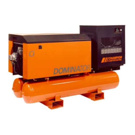
- Page 1 Parts and Operator’s Manual Ci 40 - Ci 110 Read this manual prior to installation and operation of this machine. Manual No.: 975203 Rev. H Effective: July 2002 Model : _____________ Serial Number: _____________...
-
Page 3: Table Of Contents
7.4.4 System Isolating Gate Valve Check.......14 OPERATION ..................15 Start-Up Procedure ..............15 Function Of Controls ...............15 8.2.1 Stop / Start (Standard Ci 40 - 75): .........15 8.2.2 Star-delta, CSU (Option Ci75, Standard Ci 110):...16 Control Pressure Switch............17 Protection Devices ..............18 Thermo Bypass-Valve.............18... - Page 4 10.3.1 Initial Service - 250 hours ..........27 10.3.2 Every 1,500 Hours............27 10.3.3 Every 3,000 Hours (Or Yearly)........27 11.0 GENERAL ASSEMBLY COMPONENTS - Ci 40 / 55......30 12.0 GENERAL ASSEMBLY COMPONENTS- Ci 75........ 34 13.0 GENERAL ASSEMBLY COMPONENTS- Ci 110......40 14.0...
- Page 5 Champion Compressors Ltd. Manual No. 975203 Rev H 24.0 LEAD / LAG CONTROL BOX ASSEMBLY ........68 25.0 DUPLEX ASSEMBLIES ..............70 26.0 TROUBLESHOOTING...............72 27.0 GENERAL ARRANGEMENT DRAWINGS ........73 29.0 CHAMPION NETWORK ..............91 APPENDIX A DN - METRIC NOMINAL SIZES ..........94...
-
Page 7: Parts Ordering Procedure
When ordering parts always indicate the Serial No. and Model No. of the compressor. The parts should be ordered from the nearest Champion Branch or Champion Distributor from whom the compressor was purchased (see 29.0 Champion Network). If for any reason parts cannot be obtained in this manner, please contact Champion Compressors Head Office directly. -
Page 8: Recommended Spare Parts List
(freight pre-paid), with proof of purchase to Champion Compressors. In general, machine spare parts are warranted for six months from the date of invoice and subject to Champion Compressors Ltd. standard Warranty Policy, and... -
Page 9: Introduction
Please familiarise yourself with the contents before placing the unit into service. Correct installation and on going maintenance using the Champion Maintenance Program and Service Contract will provide years of trouble-free service. A copy of this manual should be given to the personnel responsible for operating the machine within your organisation. -
Page 10: Safety
Manual No. 975203 Rev H SAFETY General Safety Notes Champion Compressors manufacture the Dominator Ci series so that they can be operated safely. Persons operating the compressor are ultimately responsible for their own safety. The following safety precautions are suggested as a guide to reduce the risk of injuries throughout the life of your compressor. - Page 11 Champion Compressors Ltd. Manual No. 975203 Rev H Avoid touching hot fluid, hot surfaces and points of air discharge. The surfaces of the cooler, motor and airend can become very hot in high ambient conditions. • Do not directly breathe the air from this compressor.
-
Page 12: General Description And Operation
Support Division should you wish to vary the operating pressure of your machine. As standard, each compressor is mounted on an air receiver. The Ci 40 & 55 is mounted on one 150L air receiver, and the Ci 75 & 110 are mounted on twin tank 220L air receivers. -
Page 13: Principle Of Operation
Champion Compressors Ltd. Manual No. 975203 Rev H The Ci 110 uses a three phase star-delta starter panel mounted in the lid of the compressor cabinet. This machine runs continuously, loading and unloading as required to meet system pressure needs. An Off/Auto switch mounted in the lid panel of the compressor is provided as a means of control. -
Page 14: Control System
The pressure switch then de-energises the solenoid valve, closing the intake valve and allowing the integrated screw to reduce sump pressure. On the stop/start models (standard on Ci 40, 55, 75) the compressor will come to a stop. The load/unload models (standard Ci 110) will continue to... -
Page 15: Technical Data
If circuit breakers are to be used, use only circuit breakers equivalent to MOTOR START FUSE. ♣ Refer Champion Service if a change from mineral based oil to synthetic is required. † Overload settings in brackets are for Ci-75 with Star-delta starter. -
Page 16: Installation And Pre Start Checks
Connection To Air System The compressor is supplied with either a 3/4” Gate valve (Ci 40/55) or 1” Gate Valve (Ci 75/110) loose for installation into to ends of the compressor’s air receiver. The connecting plant airline connection should be at least the size of the prescribed gate valve, and if the pipe run is of any great length, the pipe sizes should be increased by one size to minimise any pressure drop. -
Page 17: Electrical Connection
Refer to Section 6 - ‘Technical Data’. NEUTRAL CONNECTION IS REQUIRED ON SOME MODELS. Champion Compressors has provided a circuit diagram at the rear of this operator’s manual 7.3.1 Ci 40 - 75 (Stop / start control) All the mains supply leads connect to the compressor within the cover of the combination pressure switch and starter. -
Page 18: Ci 75 / 110 (Star-Delta, Csu)
Champion Compressors Ltd. Manual No. 975203 Rev H 7.3.2 Ci 75 / 110 (Star-delta, CSU) The main supply leads connect to the compressor through conduit entry points on both the cabinet panels and electrical enclosure. The three phase wires connect directly to terminals marked. Connection of the earth wire should be bolted to the starter enclosure using the M6 earthing bolt provided. -
Page 19: Mechanical Checks
Correct belt tension is achieved with the use of a Tensiometer (Champion Part No. 270965). Refer to Figure 3. Set the large o-ring so that the o-ring bottom is at the 7mm mark. Ensure that the small o-ring is set at the zero mark. -
Page 20: System Isolating Gate Valve Check
Champion Compressors Ltd. Manual No. 975203 Rev H The belt tension must be adjusted between the minimum, maximum and initial values (1.3 x Maximum) listed in the table below: Model Minimum Maximum Initial Ci 40 1.3 kg 1.8 kg 2.3 kg Ci 55 1.4 kg... -
Page 21: Operation
8.2.1 Stop / Start (Standard Ci 40 - 75): The On / Off control, and system pressure gauge for the Ci 40 - 75 machines is located on the pressure switch / starter assembly. While the switch is in the ‘Auto’... -
Page 22: Star-Delta, Csu (Option Ci75, Standard Ci 110)
The factory setting of this timer is six minutes, but it may be adjusted with specific installation requirements. Please refer to Champion Compressors prior to any adjustments being made, as an incorrect setting may result in damage to the compressor. -
Page 23: Control Pressure Switch
- turn differential screw anticlockwise For safety reasons, under no circumstances adjust the setting differently to the ones listed above. If different pressure settings are desired refer to your Champion Compressors Service Agent Adjust under pressure Fig. 4 - Control Pressure Switches... -
Page 24: Protection Devices
Champion Compressors Ltd. Manual No. 975203 Rev H Protection Devices The Dominator range is protected by a high oil temperature switch (set at 100°C) and a motor thermal overload (settings detailed in Section 6). On the Stop / Start models, the temperature switch trips the motor overload (located in the pressure switch) and this requires manual resetting (switch off / switch on). -
Page 25: Options
Champion Compressors Ltd. Manual No. 975203 Rev H OPTIONS The following is a selection of options, which may have been ordered with your compressor. Lead/Lag, Remote Monitoring & Control. A pair of compressors may be controlled by a central control box, equipping the package with ‘Lead / Lag’, ‘Duty / Standby’, and ‘Remote monitoring and... -
Page 26: Central Control Box Operation
Champion Compressors Ltd. Manual No. 975203 Rev H Remote monitoring of the compressor status, (“Fault”, “Standby”, “Run”), is achieved by utilising the voltage-free contacts contained within the control box. Remote Control of the compressors is achieved by connecting a remote switch to the terminals contained within the control box. - Page 27 Champion Compressors Ltd. Manual No. 975203 Rev H ‘Compressor A or Compressor B’ - Set the “A / B / AB” selector switch to either ‘A’ or ‘B’ to run one compressor only. The other compressor will not run, it can be switched to run in the event of the primary compressor being out of service, i.e.
-
Page 28: Lead/Lag Control
Champion Compressors Ltd. Manual No. 975203 Rev H Lead/Lag Control. Similar to the central control box, a pair of compressors may be controlled by a lead/lag control box, equipping the package with ‘lead / lag’ capability. Lead/Lag controls allow two compressors to operate in tandem. One unit is selected to be the lead unit and the other the lag unit. -
Page 29: Lead / Lag Pressure Switches
Champion Compressors Ltd. Manual No. 975203 Rev H When a fault is detected, or the Emergency Stop button is depressed, the machine will not start until the fault is removed and the Fault Reset button is pressed. Lead / Lag Pressure Switches The central and lead / lag control boxes contain two pressure switches, (lead and lag), which have been factory set as listed below. -
Page 30: Acoustic Hood (Ci 40/55)
Manual No. 975203 Rev H Acoustic Hood (Ci 40/55). The Ci 40/55 Dominators are available with an acoustic hood. This cabinet helps to reduce the noise level, as well as acting as a protective cover for the compressor. Ci75 / 110 models have the hoods fitted as standard. -
Page 31: Base-Mount
/ filter(s) before entering the ‘dry’ receiver. An additional filter may be fitted at the discharge of the ‘dry’ receiver. The Dirty Environment Filter and Acoustic Hood (Ci 40 / 55) options are available in conjunction with the Duplex option. Base-mount Where an air receiver or equivalent exists at the installation location, a Dominator may be ordered without an integrated receiver. -
Page 32: 10.0 Maintenance
Champion Compressors offers a variety of Maintenance Management solutions which provide regular maintenance to ensure long life and trouble free service from your compressor. Contact your Champion Compressors representative to arrange this service. 10.2 Daily Operation Prior to starting drain any water from oil sump through drain valve until oil begins to flow (Oil floats on water). -
Page 33: Maintenance Schedule
10.3.1 Initial Service - 250 hours The oil should be changed after the first 250 hours of service, and then after every 1,500* hours of service. Use only Champion recommended oil. (See Section 6 for 'Recommended Lubricants') 10.3.2 Every 1,500 Hours Change the compressor oil and oil filter (use prescribed grade only)*. - Page 34 Champion Compressors Ltd. Manual No. 975203 Rev H THIS PAGE HAS BEEN LEFT BLANK...
- Page 35 Champion Compressors Ltd. Manual No. 975203 Rev H A.R. = As Required N.S.S. = Not Sold Separately...
-
Page 36: General Assembly Components - Ci 40 / 55
Champion Compressors Ltd. Manual No. 975203 Rev H 11.0 GENERAL ASSEMBLY COMPONENTS - Ci 40 / 55... - Page 37 351253 Motor - 5.5 kW - 2P - IP55 - TOP - Multivoltage - Ci 55 351276 Motor - 4.0 kW - 2P - IP55 - TOP - Multivoltage - Ci 40 301023 Integrated Screw - Ci 40 & 55 681718 Hose Assy - 3/8”...
- Page 38 Champion Compressors Ltd. Manual No. 975203 Rev H 11.0 GENERAL ASSEMBLY COMPONENTS - Ci 40 / 55 (Continued)
- Page 39 Description Qty. Airend Pulleys 401312 Pulley - 2 SPZ x 106 - 1610 T/L - Ci 40 - 7 & 10 bar 401284 Pulley - 2 SPZ x 118 - 1610 T/L - Ci 40 - 13 bar 401304 Pulley - 2 SPZ x 95 - 1610 T/L - Ci 55 - 7,10 & 13 bar 411036 Taperlock Bush - Airend - 1610-25 - Ci 40 &...
-
Page 40: General Assembly Components- Ci 75
Champion Compressors Ltd. Manual No. 975203 Rev H 12.0 GENERAL ASSEMBLY COMPONENTS- Ci 75... - Page 41 Champion Compressors Ltd. Manual No. 975203 Rev H 12.0 GENERAL ASSEMBLY COMPONENTS - Ci 75 - (9800657 Rev H) Item Part No. Description Qty. 511135 Air Receiver 301020 Airend - Integrated Screw Motors - 380/415 V 50 Hz, 440V 60Hz 351274 Motor - 7.5kW - 2P - TOP - IP55 - Multivoltage...
- Page 42 Champion Compressors Ltd. Manual No. 975203 Rev H 12.0 GENERAL ASSEMBLY COMPONENTS- Ci 75 (Continued)
- Page 43 Champion Compressors Ltd. Manual No. 975203 Rev H 12.0 GENERAL ASSEMBLY COMPONENTS - Ci 75 - (9800657 Rev H) - Continued Item Part No. Description Qty. 9800673-5 Sound Foam - Roof Panel - Rear 9800673-7 Sound Foam - Roof Panel - Front...
- Page 44 Champion Compressors Ltd. Manual No. 975203 Rev H 12.0 GENERAL ASSEMBLY COMPONENTS- Ci 75 (Continued)
- Page 45 Champion Compressors Ltd. Manual No. 975203 Rev H 12.0 GENERAL ASSEMBLY COMPONENTS - Ci 75 - (9800657 Rev H) - Continued Item Part No. Description Qty. 861018 Seal Strip - 15mm wide 861089 Handle - Pocket - Ci Series 861099...
-
Page 46: General Assembly Components- Ci 110
Champion Compressors Ltd. Manual No. 975203 Rev H 13.0 GENERAL ASSEMBLY COMPONENTS- Ci 110... - Page 47 Champion Compressors Ltd. Manual No. 975203 Rev H 13.0 GENERAL ASSEMBLY COMPONENTS - Ci 110 - (9800745 Rev E) Item Part No. Description Qty. 511135 Air Receiver 301020 Airend - Integrated Screw Motors - 380/415/440 V 50 Hz, 440V 60Hz...
- Page 48 Champion Compressors Ltd. Manual No. 975203 Rev H 13.0 GENERAL ASSEMBLY COMPONENTS - Ci 110 (Continued)
- Page 49 Champion Compressors Ltd. Manual No. 975203 Rev H 13.0 GENERAL ASSEMBLY COMPONENTS - Ci 110 - (9800745 Rev E) - Continued Item Part No. Description Qty. 631173 Bush - Reducing - 1/2"BSP M to 1/4"BSP F 541026 Gate Valve - 1” BSP 621220 Nipple - Gal - 1”...
-
Page 50: Integrated Screw Components- Ci 40 / 55
Champion Compressors Ltd. Manual No. 975203 Rev H 14.0 INTEGRATED SCREW COMPONENTS- Ci 40 / 55... - Page 51 Champion Compressors Ltd. Manual No. 975203 Rev H 14.0 INTEGRATED SCREW COMPONENTS - Ci 40 / 55 (98001013 Rev A) Item Part No. Description Qty. 301023 Airend - Integrated Screw 278780 Sight Glass - Oil N.S.S. Cap Screw 621064 Plug - 1/8” BSP Black N.S.S.
- Page 52 Champion Compressors Ltd. Manual No. 975203 Rev H 15.0 INTEGRATED SCREW COMPONENTS- Ci 75 / 110...
- Page 53 278879 Oil Return Orifice Repair Kits 278875 Kit - Thermovalve 70º-Includes Items 17,18, 20 278876 Kit - Thermovalve 80º-Includes Items 17,18, 20 278763 Kit - Airend Seals Ci 40-110 278874 Kit - O-rings - Includes Items 18, 24, 25, 26...
-
Page 54: Electrical Starter Assembly - Ci75Sd/110
Champion Compressors Ltd. Manual No. 975203 Rev H 16.0 ELECTRICAL STARTER ASSEMBLY - Ci75SD/110... - Page 55 Champion Compressors Ltd. Manual No. 975203 Rev H 16.0 ELECTRICAL STARTER ASSEMBLY - Ci75SD / 110 - (9800746 Rev C) Item Part No. Description Qty. Internal Electrical 712184 Transformer - 415/240V - 60 VA 712396 Transformer - 60VA Multi-Input To 240V - Export...
- Page 56 Champion Compressors Ltd. Manual No. 975203 Rev H 16.0 ELECTRICAL STARTER ASSEMBLY - Ci75SD/110 (Continued)
- Page 57 Champion Compressors Ltd. Manual No. 975203 Rev H 16.0 ELECTRICAL STARTER ASSEMBLY - Ci75SD / 110 - (9800746 Rev C) - Continued Item Part No. Description Qty. 712004 Emergency Stop Button N.S.S Locknut - Button 712067 On/Off Switch - 2 Position N.S.S...
-
Page 58: Clean Air Pack Assemblies
Champion Compressors Ltd. Manual No. 975203 Rev H 17.0 CLEAN AIR PACK ASSEMBLIES... - Page 59 Manual No. 975203 Rev H 17.0 CLEAN AIR PACK ASSEMBLIES - (9800668 Rev E) Item Part No. Description Qty. Clean Air Pack Components - Ci 40 & Ci 55 182006 Refrigerated Dryer - Champion CRD006 182009 Refrigerated Dryer - Champion CRD009 521326 Mount W.A - Dryer...
- Page 60 Champion Compressors Ltd. Manual No. 975203 Rev H 17.0 CLEAN AIR PACK ASSEMBLIES (Continued)
- Page 61 CLEAN AIR PACK ASSEMBLIES - (9800668 Rev E) - Continued 601086 Washer - M10 Spring 601147 Taptite - Hex - Washer Face - M8x36 211560 Micro Filter - Champion G7ZD 211760 G7ZD Filter Element 541025 Gate Valve - ¾” - CRD012 541026 Gate Valve - 1”...
-
Page 62: Cyclopac Air Intake Assemblies
Champion Compressors Ltd. Manual No. 975203 Rev H 18.0 CYCLOPAC AIR INTAKE ASSEMBLIES... - Page 63 Manual No. 975203 Rev H 18.0 CYCLOPAC AIR INTAKE ASSEMBLIES - (9800688 Rev D) Item Part No. Description Qty. Ci 40 - 55 561354 Clamp - Hose - Worm Drive - 40 to 60 mm 561096 Rubber - 90 Deg Elbow 681570 Tube - Aluminised - 2”...
-
Page 64: Acoustic Hood Assembly
Champion Compressors Ltd. Manual No. 975203 Rev H 19.0 ACOUSTIC HOOD ASSEMBLY... - Page 65 Champion Compressors Ltd. Manual No. 975203 Rev H 19.0 ACOUSTIC HOOD ASSEMBLY - (9800689 Rev E) Item Part No. Description Qty. 872557 Panel - Compressor Top - 820 x 570 x 100 872558 Panel - Rear 872349 Angle - Support - 20 x 20 x 2 - 474 Long...
-
Page 66: Autodrain Assembly
Champion Compressors Ltd. Manual No. 975203 Rev H 20.0 AUTODRAIN ASSEMBLY... - Page 67 Champion Compressors Ltd. Manual No. 975203 Rev H 20.0 AUTODRAIN ASSEMBLY - (9800992 Rev A) Item Part No. Description Qty. 621559 Elbow - ½” BSPF Swivel x ½” BSPM 621676 Nipple - Hex ½” 316SS - BSP 621672 Tee - ½” 316SS BSP 631003 Fitting - T ½”...
-
Page 68: Control Box Door Assembly
Champion Compressors Ltd. Manual No. 975203 Rev H 21.0 CONTROL BOX DOOR ASSEMBLY... - Page 69 Champion Compressors Ltd. Manual No. 975203 Rev H 21.0 CONTROL BOX DOOR ASSEMBLY (Duplex option only)- (9800720 Rev A) Item Part No. Description Qty. 712079 Contact Block - N/C & N/O 712144 Holder - Switch or Lamp - Labelled 712145...
-
Page 70: Central Control Box Assembly
Champion Compressors Ltd. Manual No. 975203 Rev H 22.0 CENTRAL CONTROL BOX ASSEMBLY... - Page 71 Champion Compressors Ltd. Manual No. 975203 Rev H 22.0 CENTRAL CONTROL BOX ASSEMBLY (Duplex option only)- (9800719 Rev B) Item Part No. Description Qty. 712028 Contactor - CL25 712045 Overload - RT1P 781117 Hour Meter - 240V - Din Rail Mount...
-
Page 72: Lead / Lag Control Box Door Assembly
Champion Compressors Ltd. Manual No. 975203 Rev H 23.0 LEAD / LAG CONTROL BOX DOOR ASSEMBLY... - Page 73 Champion Compressors Ltd. Manual No. 975203 Rev H 23.0 LEAD / LAG CONTROL BOX DOOR ASSEMBLY - (9800862 Rev A) Item Part No. Description Qty. 712144 Holder - Switch or Lamp - Labelled 712004 Push Button - Emergency Stop 712067...
-
Page 74: Lead / Lag Control Box Assembly
Champion Compressors Ltd. Manual No. 975203 Rev H 24.0 LEAD / LAG CONTROL BOX ASSEMBLY... - Page 75 Champion Compressors Ltd. Manual No. 975203 Rev H 24.0 LEAD / LAG CONTROL BOX ASSEMBLY - (9800889 Rev A) Item Part No. Description Qty. 712028 Contactor - CL25 712045 Overload - RT1P 712043 Overload - RT1N 712046 Overload - RT1S...
-
Page 76: Duplex Assemblies
Champion Compressors Ltd. Manual No. 975203 Rev H 25.0 DUPLEX ASSEMBLIES... - Page 77 Champion Compressors Ltd. Manual No. 975203 Rev H 25.0 DUPLEX ASSEMBLIES - (9800723 Rev D) Item Part No. Description Qty. 511138 Air Receiver - 440 x 1800 159019 Central Control Box - Lead / Lag, Remote Monitoring / Control 711897...
-
Page 78: Troubleshooting
Lower system pressure. Faulty solenoid valve. Replace solenoid valve. 26.4 Compressor does not provide enough air. Too much air usage. Contact Champion. Compressor may be too small. Inlet filter blocked. Clean or replace. Throttle not opening fully. Overhaul / replace. -
Page 79: 27.0 General Arrangement Drawings
Champion Compressors Ltd. Manual No. 975203 Rev H 27.0 GENERAL ARRANGEMENT DRAWINGS Fig. 8 - Ci 40 / 55 Standard. - Page 80 Champion Compressors Ltd. Manual No. 975203 Rev H Fig. 9 - Ci 75 Standard.
- Page 81 Champion Compressors Ltd. Manual No. 975203 Rev H Fig. 10 - Ci 75SD / 110 Standard.
- Page 82 Champion Compressors Ltd. Manual No. 975203 Rev H Fig. 11 - Ci 40 / 55 Acoustic Hood.
- Page 83 Champion Compressors Ltd. Manual No. 975203 Rev H Fig. 12 - Ci 40 Dryer Option.
- Page 84 Champion Compressors Ltd. Manual No. 975203 Rev H Fig 13 - Ci 55 Dryer Option.
- Page 85 Champion Compressors Ltd. Manual No. 975203 Rev H Fig. 14 - Ci 75 Dryer Option.
- Page 86 Champion Compressors Ltd. Manual No. 975203 Rev H Fig. 15 - Ci 75SD Dryer Option.
- Page 87 Champion Compressors Ltd. Manual No. 975203 Rev H Fig. 16 - Ci 110 Dryer Option.
- Page 88 Champion Compressors Ltd. Manual No. 975203 Rev H Fig. 17 - Ci 40 / 55 Base Mount.
- Page 89 Champion Compressors Ltd. Manual No. 975203 Rev H Fig. 18 - Ci 40 / 55 Base Mount with Acoustic Hood.
- Page 90 Champion Compressors Ltd. Manual No. 975203 Rev H Fig. 19 - Ci 75 Base Mount.
- Page 91 Champion Compressors Ltd. Manual No. 975203 Rev H Fig. 20 - Ci 75SD / 110 Base Mount.
- Page 92 Champion Compressors Ltd. Manual No. 975203 Rev H Fig. 21 - Ci 75 Cyclopac Option.
- Page 93 Champion Compressors Ltd. Manual No. 975203 Rev H Fig. 22 - Ci 75SD / 110 Cyclopac Option.
- Page 94 Champion Compressors Ltd. Manual No. 975203 Rev H Fig. 23 - Ci 40 - 110 Duplex (Control Box & Clean Air Pack shown).
- Page 95 How does it compare to your expectations? Other Comments:__________________________________________________________ ________________________________________________________________________ Other comments related to our level of service during the purchasing, delivery and commissioning process:_____________________________________________________ ________________________________________________________________________ ________________________________________________________________________ Please detach this page and fax it to: Champion Compressors Head Office (Melbourne): (+613) 9703 8077...
- Page 96 Champion Compressors Ltd. Manual No. 975203 Rev H 28.0 CUSTOMER FEEDBACK SHEET Please return fax this document to : Champion Compressors (+613) 9703 8077...
-
Page 97: 29.0 Champion Network
Champion Compressors Ltd. Manual No. 975203 Rev H 29.0 CHAMPION NETWORK FACTORY AND HEAD OFFICE Princes Highway, Hallam, Victoria 3803 Tel: (613) 9703 8000 Fax: (613) 9703 8053 AUSTRALIAN SALES AND SERVICE LOCATIONS NEW SOUTH WALES Champion Compressors Ltd Champion Compressors Ltd... - Page 98 Champion Compressors Ltd. Manual No. 975203 Rev H VICTORIA WESTERN AUSTRALIA Champion Compressors Ltd Champion Compressors Ltd Princes Highway, 46 Sorbonne Crescent, Hallam, VIC, 3803 Canning Vale, WA, 6155 Ph: (03) 9703 8080 Ph: (08) 9455 4911 Fax: (03) 9703 8099...
- Page 99 Champion Compressors Ltd. Manual No. 975203 Rev H 29.0 CHAMPION NETWORK (Continued) FACTORY AND HEAD OFFICE Princes Highway, Hallam, Victoria 3803 Tel: (+613) 9703 8000 Fax: (+613) 9703 8053 INTERNATIONAL DISTRIBUTORS AND SERVICE LOCATIONS Finland Malaysia Scandinavian Champions Oy Compressed Air Packaging & Services Vakkistentie 22 Sdn.
-
Page 100: Appendix A Dn - Metric Nominal Sizes
Champion Compressors Ltd. Manual No. 975203 Rev H APPENDIX A DN - METRIC NOMINAL SIZES DN - Nominal Size for Valves, Flanges and Fittings. International Definition see ISO 6708-1980 Nominal size (DN): A numerical designation of size which is common to all components in a piping system other than components designated by outside diameters or by thread size. - Page 101 Any alterations or modifications to the equipment carried out by any 9. TERMS AND CONDITIONS OF SALE OF GOODS This warranty policy is to be read in conjunction with Champion party, without the express written approval of the Seller, will render the warranty null and void.
Need help?
Do you have a question about the ci 40 and is the answer not in the manual?
Questions and answers