Table of Contents
Advertisement
OPERATION/MAINTENANCE
MANUAL & PARTS LIST
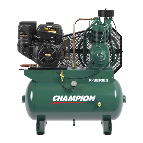
Diesel Engine Driven Two Stage Air
Compressor Featuring the R15BHU Compressor
THIS MANUAL CONTAINS IMPORTANT SAFETY INFORMATION AND SHOULD ALWAYS BE
AVAILABLE TO THOSE PERSONNEL OPERATING THIS UNIT.
READ, UNDERSTAND AND RETAIN ALL INSTRUCTIONS BEFORE OPERATING THIS
EQUIPMENT TO PREVENT INJURY OR EQUIPMENT DAMAGE.
MODELS
HDR5–3K
HDR5–3Y
HDR5-8K
HDR5-8Y
BDR5K
BDR5Y
Form No. CQF3355
VER: 02
12/22/2014
Advertisement
Table of Contents

Subscribe to Our Youtube Channel
Related Manuals for Champion HDR5–3K


Summary of Contents for Champion HDR5–3K
- Page 1 OPERATION/MAINTENANCE MANUAL & PARTS LIST Diesel Engine Driven Two Stage Air Compressor Featuring the R15BHU Compressor THIS MANUAL CONTAINS IMPORTANT SAFETY INFORMATION AND SHOULD ALWAYS BE AVAILABLE TO THOSE PERSONNEL OPERATING THIS UNIT. READ, UNDERSTAND AND RETAIN ALL INSTRUCTIONS BEFORE OPERATING THIS EQUIPMENT TO PREVENT INJURY OR EQUIPMENT DAMAGE.
-
Page 3: Maintain Compressor Reliability And Performance
Reliability in materials and quality assurance are incorporated in our genuine replacement parts. Your authorized Champion Compressor distributor offers all the backup you’ll need. A worldwide network of authorized distributors provides the finest product support in the air compressor industry. -
Page 4: Table Of Contents
TABLE OF CONTENTS _______________________________________________________ Subject Page Maintain Compressor Reliability And Performance ................1 Safety And Operation Precautions ....................3 Explanation Of Safety Instruction Symbols And Decals ..............4 Introduction ............................. 5 Warranty ............................5 Dimensions And Specifications ......................6 Installation ............................7 Operation ............................ -
Page 5: Safety And Operation Precautions
Safety and Operation Precautions can result in injuries or equipment damage. However, Champion does not state as fact or does not mean to imply that the preceding list of Safety and Operating Precautions is all inclusive, and further that the observance of this list will prevent all injuries or... -
Page 6: Explanation Of Safety Instruction Symbols And Decals
Indicates immediate hazards which will result in severe injury or death. Indicates hazards or unsafe practice which could result in severe injury or death. Indicates hazards or unsafe practice which could result in damage to the Champion compressor or minor injury. -
Page 7: Introduction
(60) months from date of installation or sixty-six (66) months from date of shipment by CHAMPION or CHAMPION distributor, whichever may occur first. Applies to the compressor pump only, excluding head valves. Valves, controls and accessories are warranted for the first year only. -
Page 8: Dimensions And Specifications
TWO STAGE AIR COMPRESSORS - MODEL R15BHU DIMENSIONS ITEM R15BHU Base-Width 10” Bolt Down-Width 4-3/8” Bolt Down to Edge 5/8” Base to Crank Ctr 5-1/2” Overall Width 18” Overall Height 23-1/4” Bolt Down Hole Dia. 15/32” Base-Depth 7-1/2” Bolt Down Depth 5-3/4”... -
Page 9: Installation
It is recommended that unit be set on optional vibro-isolator pads. Tanks bolted directly to a floor without isolators will not be warranted against cracking. Champion vibro-isolators or approved equivalent must be installed for extended warranty to apply to ASME receivers. - Page 10 Do not install isolating valves between compressor outlet and air receiver. This will cause excessive pressure if valve is closed, and cause injury and equipment damage. Always use an air pressure regulating device at the point of use. Failure to do so can result in injury or equipment damage.
-
Page 11: Operation
OPERATION This compressor has been inspected, thoroughly tested and approved at the factory. For this unit to give long satisfactory service it must be installed and operated properly. This compressor has been designed for an 80%/ON – 20%/OFF duty cycle. R15B models are equipped with a pilot valve and head unloaders to provide continuous run capabilities. -
Page 12: Maintenance
GUIDE TO MAINTENANCE For Service contact an authorized Champion distributor. All requests should include model number and serial number. To obtain reliable and satisfactory service, this unit requires a consistent preventive maintenance schedule. Maintenance schedule form is included to aid in keeping the proper records, See Pages 32 &... - Page 13 EVERY 90 DAYS OR 500 HOURS MAINTENANCE Change compressor crankcase oil and oil filter. Use only Champlub recip lubricant. Check entire system for air leakage around fittings, connections, and gaskets, using soap solution and brush. Tighten nuts and cap screws as required. Check and clean compressor valves as required.
-
Page 14: Compressor Pilot Valve Differential Pressure Adjustment
GENERAL MAINTENANCE (Cont'd.) THE INTERSTAGE PRESSURE RELIEF VALVE is provided to protect against interstage over pressure and is factory set for maximum pressure of 75 PSIG. DO NOT RESET. If the pressure relief valve pops, it indicates trouble. Shut down the unit immediately and determine and correct the malfunction. -
Page 15: Compressor Oil Specifications
“Emulsification of oil (white milky substance) indicates unsafe accumulation of moisture and may be evidence compressor is oversized for application. Failure to promptly consult your local distributor, or Champion Customer Service, can be grounds to deny warranty.” NOTES: 1. Normal break-in period of Champion air compressors is 25 hours. -
Page 16: Trouble Shooting Guide
TROUBLE SHOOTING CHART FOR COMPRESSOR Always shut off unit and relieve all pressure from air tank before performing any maintenance. Failure to do so may result in equipment damage or injury. Never operate unit without belt guard in place Symptom Possible Cause(s) Corrective Action Engine will not start. - Page 17 UNIT REPAIR PARTS ILLUSTRATION MODEL: HDR5-3K, HDR5-3Y 331CAE810-A (Ref. Drawing) 30 GALLON TANK ASSEMBLY Ref. No. Description Part Number Qty. Receiver CC1111269 Mounting Plate 300CAE4017 Screw M3460 M3483 Motor Mounting Bracket 300CAE145 Eye Bolt VP1096404 Screw 655ED09AZ Elbow M980B Nipple P08798A Ball Valve VP1022988...
- Page 18 UNIT REPAIR PARTS ILLUSTRATION MODEL: HDR5-8K, HDR5-8Y 333CAE810-A (Ref. Drawing) 80 GALLON TANK ASSEMBLY Ref. No. Description Part Number Qty. Receiver CC1111231 Mounting Plate 300CAE4017 Screw M3460 M3483 Motor Mounting Bracket 300CAE145 Eye Bolt VP1096404 Screw 655ED09AZ Elbow M980B Nipple P08798A Ball Valve VP1022988...
- Page 19 UNIT REPAIR PARTS ILLUSTRATION MODEL: BDR5K, BDR5Y 313CAE810-A (Ref. Drawing) BASE PLATE GROUP Ref. No. Description Part Number Qty. Base plate 300CAE285 Mounting Plate 300CAE4017 Screw M3460 M3483 Motor Mounting Bracket 300CAE145 Eye Bolt VP1096404 Screw 655ED09AZ...
- Page 20 UNIT REPAIR PARTS ILLUSTRATION MODELS: HDR5-3K, HDR5-3Y, HDR5-8K, HDR5-8Y, BDR5K, BDR5Y 307CAE810-B (Ref. Drawing) Compressor Group Ref. No. Description Part Number Qty. R15BHU Compressor CC1119843 Screw M3460 M3483...
- Page 21 UNIT REPAIR PARTS ILLUSTRATION MODELS: HDR5-3K, HDR5-3Y 317CAE810-A (Ref. Drawing) DISCHARGE GROUP Ref. No. Description Part Number Qty. Tube Fitting M2867 Discharge Tube 303CAE857 Tube Fitting M2350 Check Valve P05822A...
- Page 22 UNIT REPAIR PARTS ILLUSTRATION MODELS: HDR5-8K, HDR5-8Y 326CAE810-A (Ref. Drawing) DISCHARGE GROUP Ref. No. Description Part Number Qty. Tube Fitting M2867 Discharge Tube 302CAE857 Check Valve P05822A...
- Page 23 UNIT REPAIR PARTS ILLUSTRATION MODELS: HDR5-3K, HDR5-8K, BDR5K 319CAE810-C (Ref. Drawing) ENGINE, DRIVE & BELT GUARD GROUP Ref. No. Description Part Number Qty. Engine VP1136277 Oil Drain VP1099934 Throttle Control Bracket CC1134655 Throttle Control Valve VP1135897 50W5 M3483 Bushing P09799A Pulley P13197A Belt...
- Page 24 UNIT REPAIR PARTS ILLUSTRATION MODELS: HDR5-3Y, HDR5-8Y, BDR5Y 318CAE810-B (Ref. Drawing) ENGINE, DRIVE & BELT GUARD GROUP Ref. No. Description Part Number Qty. Engine VP1103634 Oil Drain VP1101377 Throttle Control Bracket 303CAE017 Throttle Control VP1097563 Tube Fitting 86E229 Washer 121097Z Lock Washer 95B13Z Screw...
- Page 25 UNIT REPAIR PARTS ILLUSTRATION MODELS: HDR5-3K, HDR5-8K, BDR5K 322CAE810-A (Ref. Drawing) CONTROL GROUP Part Ref. No. Description Qty. Number Tube Fitting M2863 Elbow M3251 Tube Insert P10118A Tubing P10117A 1.9ft. Tubing P10117A .75ft. Tubing P10117A 1.01ft. Tube Fitting M2868 Delay Valve P09263A Nipple M3174...
-
Page 26: Unit Repair Parts List
UNIT REPAIR PARTS ILLUSTRATION MODELS: HDR5-3Y, HDR5-8Y, BDR5Y 321CAE810-A (Ref. Drawing) CONTROL GROUP Ref. No. Description Part Number Qty. Tube Fitting M2863 Tube Insert P10118A Tubing P10117A 1.47ft. Tubing P10117A 1.10ft. Tubing P10117A .79ft. Tube Fitting M2868 Delay Valve P09263A Nipple M3174 M3474... - Page 27 36,37 36,37 93 94 95 88 89 90 91 92 86 87 C392-B (Ref. Drawing)
- Page 28 Repair Parts List Compressor Models R10DHU & R15BHU Ref. No. Description Part Number Qty. Crankcase M1820 Pipe plug 64AA5 Flywheel NR7A Hex head cap screw M738 Hex nut M2955 Pipe plug 64A5 Oil level gauge RE714 Pipe nipple M492 Pipe cap M461 Governor housing gasket set (includes, items, 11A,11B,11C, &...
- Page 29 Repair Parts List Compressor Models R10DHU & R15BHU Ref. No. Description Part Number Qty. Piston pin R1021 Piston pin retaining ring R10102 Low pressure piston ring set Z798 High pressure piston ring set Z797 Cylinder P12237D Hex head cap screw M2345 Low pressure discharge valve assembly Z813...
- Page 30 Repair Parts List Compressor Models R10DHU & R15BHU Ref. No. Description Part Number Qty. Gasket, Valve CPQ14870A Unloader spring P01882A Guide stem P09296A Unloader finger P14119A Locking hex nut P09086A High pressure intake manifold P12304B Interstage pressure relief valve M3685 Intake filter P04999A Intake filter element...
-
Page 31: Compressor Repair Parts List
COMPRESSOR REPAIR PARTS ILLUSTRATION Models: R15BHU 305CAP810-B (Ref. Drawing) Repair Parts List Ref. No. Description Part Number Qty. Compression fitting M2868 Tube, Unloading w/Fittings ZSB250A Compression Fitting M2864 Breather Tube w/Fittings ZUB375 Compression Fitting M2879 Manifold Tube Z9172 Intercooler w/Fittings Z9140 Compression Fitting M2868... -
Page 32: Unit Hazard Decals
UNIT HAZARD DECALS... -
Page 33: Pump Hazard Decals
PUMP HAZARD DECAL LISTING DESCRIPTION PART NO. PUMP DECAL SHEET – MASTER P13805A NOT USED NOTICE - Lubricants DECAL – Rotation Direction NOTICE – Read and Retain Manuals DANGER – Breathing Air DECAL – Made in the United States of America PUMP HAZARD DECALS... -
Page 34: Maintenance Kits
MAINTENANCE KITS DESCRIPTION Qty. Part Number R10, R15 Compressor Maintenance Kit (includes the following) ..... Z11882 Air Filter Element ................P05050A Oil (1 Quart) ..................P13796A... -
Page 35: Record Of Maintenance Service
RECORD OF MAINTENANCE SERVICE RECORD OF MAINTENANCE SERVICE DAILY ● CHECK OIL LEVEL ● DRAIN MOISTURE FROM TANK WEEKLY MONTHLY EVERY 3 MONTHS ● CLEAN FILTER ● INSPECT AIR SYSTEM ● CHANGE OIL ● CLEAN COMPRESSOR ● INSPECT VALVE ASSEMBLIES ●... - Page 36 *CQF3355VER02* *CQF3355VER02* For additional information, contact your local representative or visit: www.championpneumatic.com/contactus.aspx ©2014 Gardner Denver, Inc. Printed in U.S.A.
Need help?
Do you have a question about the HDR5–3K and is the answer not in the manual?
Questions and answers