Page 1
OPERATION/MAINTENANCE MANUAL & PARTS LIST Two-Stage/Two Cylinder Cast Iron R40A Air Compressor & Units THIS MANUAL CONTAINS IMPORTANT SAFETY INFORMATION AND SHOULD ALWAYS BE AVAILABLE TO THOSE PERSONNEL OPERATING THIS UNIT. READ, UNDERSTAND AND RETAIN ALL INSTRUCTIONS BEFORE OPERATING THIS EQUIPMENT TO PREVENT INJURY OR EQUIPMENT DAMAGE.
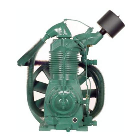
They are ready to respond and assist you by providing fast, expert maintenance and repair services. For the location of your local authorized Champion Air Compressor distributor, refer to the yellow pages of your phone directory or contact: Factory:...
Safety and Operation Precautions can result in injuries or equipment damage. However, Champion does not state as fact or does not mean to imply that the preceding list of Safety and Operating Precautions is all inclusive, and further that the observance of this list will prevent all injuries or...
WARNING Indicates hazards or unsafe practice which could result in severe injury or death. CAUTION Indicates hazards or unsafe practice which could result in damage to the Champion compressor or minor injury. NOTICE Notice is used to notify people of installation, operation or maintenance information which is important but not hazard-related.
Applies to CHAMPION logo, tank or base mounted complete compressors only. Express Limited Warranty CHAMPION warrants each new air compressor unit manufactured by CHAMPION to be free from defects in material and workmanship under normal use and service for a period of twelve (12) months from date of installation or eighteen (18) months from date of shipment by CHAMPION or CHAMPION distributor, whichever may occur first.
TWO STAGE AIR COMPRESSORS - MODEL R40A DIMENSIONS ITEM R40A Base-Width 12-7/8” Bolt Down-Width 5-11/16” Bolt Down to Edge 3/4” Base to Crank Ctr 7-15/16” Overall Width 25-1/2” Overall Height 32” HP Exhaust Opening 1NPT Bolt Down Hole Dia. 9/16”...
It is recommended that unit be set on optional vibro-isolator pads. Tanks bolted directly to a concrete floor without isolators will not be warranted against cracking. Champion vibro-isolators or approved equivalent must be installed for extended warranty to apply to ASME receivers.
Page 9
ELECTRICAL POWER SUPPLY It is essential that the power supply and the supply wiring are adequately sized and that the voltage correspond to the unit specifications. Branch circuit protection must be provided at installation a specified in the National Electrical Code. All wiring should be performed by a licensed electrician or electrical contractor.
Minimum Pipe Sizes For Compressor Air Lines (Based on clean Smooth Schedule 40 Pipe) MODEL 25’ 50’ 100’ 200’ 300’ R40A 1-1/4” (1-1/2”) 1-1/4” (1-1/2”) 1-1/4” (1-1/2”) 1-1/4” (1-1/2”) 1-1/4” (1-1/2”) Values in ( ) are for duplex unit. WARNING Never use plastic pipe or improperly rated metal pipe.
Page 11
OPERATION (CONT’D) Initial Start Up Inspect unit for any visible signs of damage that would have occurred in shipment or during installation. Pull main disconnect switch to unit to assure that no power is coming into the unit. “Lock Out” or “Tag Out”...
GUIDE TO MAINTENANCE For Service contact an authorized Champion distributor. All requests should include model number and serial number. To obtain reliable and satisfactory service, this unit requires a consistent preventive maintenance schedule. Maintenance schedule form is included to aid in keeping the proper records.
Page 13
EVERY 90 DAYS OR 500 HOURS MAINTENANCE Change crankcase oil. Use only Champlub recip lubricant. Check entire system for air leakage around fittings, connections, and gaskets, using soap solution and brush. Tighten nuts and cap screws as required. Check and clean compressor valves as required. Replace when worn or damaged parts. CAUTION Valves must be replaced in original position.
Page 14
GENERAL MAINTENANCE Cont'd.) CENTRIFUGAL UNLOADER AND UNLOADER PRESSURE RELEASE VALVE: The centrifugal unloader is operated by two governor weights. It is totally enclosed and lubricated from the crankcase of the compressor. When compressor starts, the governor weights automatically open compressing the main spring, allowing the unloader pressure release valve to close. When the compressor stops, the main spring returns the governor weights to normal position opening the unloader pressure release valve and unloading the compressor.
COMPRESSOR PILOT VALVE PRESSURE ADJUSTMENT Proceed with the following instructions while compressor is running: Loosen locknut (4) and back off several turns. Do not turn differential pressure adjustment nut (3). Check reading on the tank pressure gauge. Set the compressor maximum pressure by turning the threaded cap (1) clockwise to increase pressure or counter clockwise to decrease pressure.
“Emulsification of oil (white milky substance) indicates unsafe accumulation of moisture and may be evidence compressor is oversized for application. Failure to promptly consult your local distributor, or Champion Customer Service, can be grounds to deny warranty.” NOTES: 1. Normal break-in period of Champion air compressors is 25 hours.
TROUBLE SHOOTING CHART FOR COMPRESSOR WARNING Always disconnect unit from power supply and relieve all pressure from air tank before performing any maintenance. “Tag Out” or “Lock Out” all power sources. Failure to do so may result in equipment damage or injury. Never operate unit without belt guard in place.
Page 18
Troubleshooting Chart (cont’d) Symptom Possible Cause(s) Corrective Action Air escapes from centrifugal unloader Centrifugal unloader release valve Clean or replace valve. when unit is running. dirty or defective. Air escapes from centrifugal unloader Check valve stuck in open position. Replace check valve. when unit is stopped.
Page 19
MODELS: HRA15-12 & HRA15-25 13 (NOT SHOWN) 12 (NOT SHOWN) A.S.M.E. DATA PLATE C463-A (Ref. Drawing) REPAIR PARTS LIST MODEL HRA15-12 HRA15-25 Pump R40A R40A Pressure Gauge M519C M519C Belt Guard Z675 Z675 Drain Valve VP1022988 VP1022988 Check Valve P03690A...
Page 20
UNIT REPAIR PARTS ILLUSTRATION MODELS: BRA-15 6 (NOT SHOWN) 5 (NOT SHOWN) C464-A (Ref. Drawing) REPAIR PARTS LIST MODEL BRA-15 Pump R40A Belt Guard Z675 Base Plate P03538C Motor 15 HP P03710A Pulley 125 PSIG P05622A Pulley Bushing P09312B 175 PSIG...
UNIT REPAIR PARTS ILLUSTRATION MODELS: HRA15D-25 12, 13 (NOT SHOWN) A.S.M.E. DATA PLATE C465-A (Ref. Drawing) REPAIR PARTS LIST MODEL HRA15D-25 Pump R40A Pressure Gauge M519C Belt Guard Z675 Drain Valve VP1022988 Check Valve P03690A Bucket High Drain Z1542 P14205A...
Page 23
Repair Parts List Compressor Model R40A Ref. Part Description Qty. Number Crankcase M1453 Pipe plug 64AA5 Oil level gauge RE714 Pipe nipple M492 Pipe cap M461 Pipe plug 64A5 Oil seal P03433A Flywheel P05723C M1506 Flywheel washer M1394 Hex head cap screw M2265 Governor housing gasket set (includes items 13, 14, 15 &...
Page 24
Repair Parts List Compressor Model R40A Ref. Description Part Number Qty. Cylinder P05863D * 52 High pressure intake manifold M1431 Low pressure discharge manifold M1423 High pressure discharge manifold (Non-Base Mount Units) M1508 High pressure discharge manifold (Base Mount Units)
COMPRESSOR REPAIR PARTS ILLUSTRATION Model: R40A C473-A (Ref. Drawing) Repair Parts List Model R40A Ref. No. Description Part Number Qty. Intercooler Tube (includes compression fittings) CQZ13143 Breather Tube (includes compression fittings ZM1622 Release Valve Tube (includes compression fittings) ZM1623 3/8” x 1/4 NPT Straight Compression Fitting M2864 1/4 x 1/8”...
Page 26
CONSTANT SPEED HEAD UNLOADER FOR AIR COMPRESSOR MODEL R40A NOTE: This is optional equipment and may not be included on your unit. It is recommended constant speed unloading be used if motor starts exceed 6 starts/hour. The purpose constant speed unloading is to provide a means of stopping or starting the compression of air by the compressor without stopping or starting the electric motor or gasoline engine after each cycle.
UNIT HAZARD DECAL LISTING PAGE DESCRIPTION PART NO. PRODUCT LIABILITY DECAL SHEET - MASTER P10157A Unit Pressure Setting NOT USED DANGER – Breathing Air DANGER – Drain Tank Daily WARNING – Pressure/Safety Valve NOT USED DANGER – Valve Maintenance DANGER – High Voltage WARNING –...
RECORD OF MAINTENANCE SERVICE DAILY ● CHECK OIL LEVEL ● DRAIN MOISTURE FROM TANK WEEKLY MONTHLY EVERY 3 MONTHS ● CLEAN FILTER ● INSPECT AIR SYSTEM ● CHANGE OIL ● CLEAN COMPRESSOR ● INSPECT VALVE ASSEMBLIES ● CHECK V-BELTS ● TIGHTEN ALL FASTENERS ●...
Page 31
RECORD OF MAINTENANCE SERVICE DAILY ● CHECK OIL LEVEL ● DRAIN MOISTURE FROM TANK WEEKLY MONTHLY EVERY 3 MONTHS ● CLEAN FILTER ● INSPECT AIR SYSTEM ● CHANGE OIL ● CLEAN COMPRESSOR ● INSPECT VALVE ASSEMBLIES ● CHECK V-BELTS ● TIGHTEN ALL FASTENERS ●...