Champion R Series Operation & Service Manual
Electric drive compressors & units
Hide thumbs
Also See for R Series:
- Operation & service manual (32 pages) ,
- Operation maintenance manual & parts list (32 pages)
Table of Contents
Advertisement
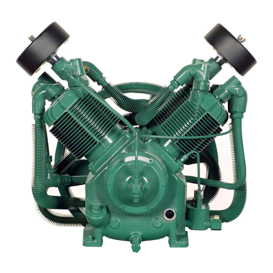
R-SERIES
Air Compressors and Units
OPERATION & SERVICE MANUAL
Electric Drive Compressors & Units
R-10/15
R-30
R-40
R-70
THIS MANUAL CONTAINS IMPORTANT SAFETY INFORMATION AND SHOULD ALWAYS
BE AVAILABLE TO THOSE PERSONNEL OPERATING THIS UNIT. READ, UNDERSTAND
AND RETAIN ALL INSTRUCTIONS BEFORE OPERATING THIS EQUIPMENT TO PREVENT
INJURY OR EQUIPMENT DAMAGE.
CQF3473 v.01
April 17, 2018
Advertisement
Table of Contents

Related Manuals for Champion R Series


Summary of Contents for Champion R Series
- Page 1 R-SERIES Air Compressors and Units OPERATION & SERVICE MANUAL Electric Drive Compressors & Units R-10/15 R-30 R-40 R-70 THIS MANUAL CONTAINS IMPORTANT SAFETY INFORMATION AND SHOULD ALWAYS BE AVAILABLE TO THOSE PERSONNEL OPERATING THIS UNIT. READ, UNDERSTAND AND RETAIN ALL INSTRUCTIONS BEFORE OPERATING THIS EQUIPMENT TO PREVENT INJURY OR EQUIPMENT DAMAGE.
- Page 2 Reliability in materials and quality assurance are incorporated in our genuine replacement parts. Your authorized Champion Compressor distributor offers all the backup you’ll need. A worldwide network of authorized distributors provides the finest product support in the air compressor industry. Your authorized distributor can support your Champion air compressor with these services: 1.
-
Page 3: Table Of Contents
Table of Contents Introduction ............................4 Safety and Operation Precautions ......................4 Explanation of Safety Instructions, Symbols, and Decals ................6 Safety and Operation Precautions ......................6 Unit Hazard Decal List – See Page 8 ......................7 Pump Hazard Decal List – See Page 9 ....................... 7 Unit Hazard Decals .......................... -
Page 4: Introduction
Introduction Champion R Series compressors are the result of advanced engineering and skilled manufacturing. To be assured of receiving maximum service from this machine the owner must exercise care in its operation and maintenance. This book is written to give the operator and maintenance department essential information for day-to-day operation, maintenance and adjustment. -
Page 5: Safety And Operation Precautions
Safety and Operation Precautions can result in injuries or equipment damage. However, Champion – A Gardner Denver Co., does not state as fact or does not mean to imply that the preceding list of Safety and Operating Precautions is all inclusive, and further that the observance of this list will prevent all injuries or equipment damage. -
Page 6: Explanation Of Safety Instructions, Symbols, And Decals
Indicates immediate hazards which will result in severe injury or death. Indicates hazards or unsafe practice which could result in severe injury or death. Indicates hazards or unsafe practice which could result in damage to the Champion compressor or minor injury. -
Page 7: Unit Hazard Decal List
Unit Hazard Decal List – See Page 8 PART NO. DESCRIPTION P10157A PRODUCT LIABILITY DECAL SHEET - MASTER Unit Pressure Setting NOT USED DANGER – Breathing Air DANGER – Drain Tank Daily WARNING – Pressure/Safety Valve NOT USED DANGER – Valve Maintenance DANGER –... -
Page 8: Unit Hazard Decals
Unit Hazard Decals R-Series Electric CQF3473 v.01 Operation & Service April 17, 2018... -
Page 9: Pump Hazard Decals
Pump Hazard Decals R-Series Electric CQF3473 v.01 Operation & Service April 17, 2018... -
Page 10: Installation
It is recommended that optional vibration isolator pads be installed with the unit. Tanks anchored directly to a concrete floor without vibration isolator pads will not be warranted against cracking. Champion vibration isolator pads must be used for extended warranty to apply to ASME air receivers. See “Air Receiver Installation” section. - Page 11 Installation (continued) Always use an air pressure regulating device at the point of use. Failure to do so can result in injury or equipment damage. ● Do not install in an area where ambient temperature is below 32°F or above 104°F. ●...
- Page 12 Installation (continued) Wiring must be such that when viewing compressor from opposite shaft end, rotation of shaft is clockwise as shown by arrow on guard. Wrong direction rotation for any length of time will result in damage to compressor. GROUNDING INSTRUCTIONS This product should be connected to a grounded, metallic, permanent wiring system, or an equipment- grounding terminal or lead on the product.
-
Page 13: Air Receiver Installation
Air Receiver Installation Vibration isolator pads can be purchased from your local authorized distributor. Installation hardware items (studs, screws, nuts, shims) are not provided. It is the compressor owner’s responsibility to provide a suitable foundation and isolator installation. Do not tighten the anchor screws/nuts down completely – this will result in undesirable stress on the tank foot. -
Page 14: Operation
Operation This compressor has been inspected, thoroughly tested and approved at the factory. For this unit to give long satisfactory service it must be installed and operated properly. This compressor has been designed for an 80%/ON – 20%/OFF duty cycle. SIMPLEX UNITS have a pressure switch that senses changes in receiver pressure and automatically starts and stops the compressor at preset pressure limits. - Page 15 Operation (continued) 3. Check compressor oil level. Add oil as required. See “Compressor Oil Specifications” Section. NOTE: Do not mix oil type, weights, or brands. 4. Activate main disconnect switch. 5. “Jog” motor and check for proper rotation by direction arrow. If rotation is wrong, reverse input connections on the magnetic starter.
-
Page 16: Low Oil Shutdown Control
Low Oil Shutdown Control (optional equipment) The oil monitor must be used in conjunction with a magnetic starter (see wiring diagram for details). The oil monitor is installed on the outside of the air compressor crankcase with a port that allows oil to feed into it’s float bowl chamber and maintain the same level as in the crankcase. - Page 17 Low Oil Shutdown Control (continued) (optional equipment) TROUBLESHOOTING & SERVICING Always disconnect unit from power supply and relieve all pressure from air tank before performing any maintenance. “Lock Out” or “Tag Out” all power sources. Failure to do so may result in personal injury or death. NOTICE Do not disassemble LOSC switch.
-
Page 18: Compressor Oil Specifications
Emulsification of oil (white milky substance) indicates unsafe accumulation of moisture and may be evidence compressor is oversized for application. Failure to promptly consult your local distributor, or Champion Customer Service, can be grounds to deny warranty. LUBRICANT - ISO 100 MINERAL... - Page 19 Compressor Oil Specifications (continued) LUBRICANT LEVEL: Maintain lubricant level at center of sight glass BREAK-IN PERIOD: 100 hours of operation or 3 months, whichever comes first. 1. Compressor must run for the break-in period using CHAMPLUB ISO 100 lubricant. 2. During the break-in period, a careful and regular check of the oil level should be made. Maintain oil level at the full line.
-
Page 20: Guide To Maintenance
Guide to Maintenance To obtain reliable and satisfactory service, this unit requires a consistent preventive maintenance schedule. Maintenance schedule pages are included in the back of this manual to aid in keeping the proper records. Before performing any maintenance function, switch main disconnect switch to "off" position to assure no power is entering unit. - Page 21 Guide to Maintenance (continued) PILOT VALVE: The pilot valve actuates the head unloader mechanism to provide a means of stopping or starting the compression of air by the compressor without stopping or starting the engine. The pilot valve is pre-set from the factory, according to the order specification. Only a certified field service technician should make adjustments to the pilot valve.
- Page 22 Guide to Maintenance (continued) COMPRESSOR VALVES: If compressor fails to pump air or seems slow in filling up tank, disconnect unit from power source and remove valves and clean thoroughly, using compressed air and a soft wire brush. After cleaning, exceptional care must be taken that all parts are replaced in exactly the same position.
- Page 23 Guide to Maintenance (continued) MOTOR LUBRICATION: Long life satisfactory operation of an electric motor depends in large measure on proper lubrication of the bearings. Bearing grease will lose its lubricating ability overtime, not suddenly. Refer to the motor manufacturer’s instructions for the type of grease and lubrication intervals.
- Page 24 Guide to Maintenance (continued) SETTING BELT TENSION 1. Proper setting of the belt tension requires a belt tension checker (part number TEN011452). 2. Measure the belt span. 3. On the belt tension checker, position the o-ring on the span scale at the measured belt span.
- Page 25 Guide to Maintenance (continued) BELT DEFLECTION FORCE MODEL H.P. MOTOR BELT BELT USED BELT NEW BELT PULLEY SECTION NUMBER DEFLECTION DEFLECTION O.D. BELTS FORCE FORCE (lbs. min) (lbs. max) 5.15 4.35 7.75 7.35 7.35 6.95 125/175 8.95 7.00 6.20 8.35 8.15 125/175 1049...
-
Page 26: Maintenance Checklist
Maintenance Checklist DAILY MAINTENANCE Check oil level of both compressor and engine if equipped. Add quality lubricating oil as required. See Section on "Oil Specifications". Drain moisture from tank by opening tank drain valve located in bottom of tank. Do not open drain valve if tank pressure exceeds 25 PSIG. -
Page 27: Troubleshooting Chart
Troubleshooting Chart Always disconnect unit from power supply and relieve all pressure from air tank before performing any maintenance. Failure to do so may result in personal injury or death. “Lock Out" or "Tag Out" all power sources. Never operate unit without belt guard in place. Never use gasoline or flammable solvent on or around compressor unit. - Page 28 Troubleshooting Chart (continued) Symptom Possible Cause(s) Corrective Action Interstage pressure relief valve 1. Defective compressor valves. 1. Install new valves. pops off. 2. Improper valve installation. 2. Verify proper valve placement. Excessive oil consumption. 1. Dirty air filter. 1. Clean or replace. 2.
-
Page 29: Maintenance Log
Maintenance Log DAILY ● CHECK OIL LEVEL ● DRAIN MOISTURE FROM TANK WEEKLY MONTHLY EVERY 3 MONTHS ● CLEAN FILTER ● INSPECT AIR SYSTEM ● CHANGE OIL ● CLEAN COMPRESSOR ● INSPECT VALVE ASSEMBLIES ● TIGHTEN ALL FASTENERS ● TEST PRESSURE RELIEF VALVE R-Series Electric CQF3473 v.01 Operation &... - Page 30 Maintenance Log DAILY ● CHECK OIL LEVEL ● DRAIN MOISTURE FROM TANK WEEKLY MONTHLY EVERY 3 MONTHS ● CLEAN FILTER ● INSPECT AIR SYSTEM ● CHANGE OIL ● CLEAN COMPRESSOR ● INSPECT VALVE ASSEMBLIES ● TIGHTEN ALL FASTENERS ● TEST PRESSURE RELIEF VALVE R-Series Electric CQF3473 v.01 Operation &...
- Page 31 Maintenance Log DAILY ● CHECK OIL LEVEL ● DRAIN MOISTURE FROM TANK WEEKLY MONTHLY EVERY 3 MONTHS ● CLEAN FILTER ● INSPECT AIR SYSTEM ● CHANGE OIL ● CLEAN COMPRESSOR ● INSPECT VALVE ASSEMBLIES ● TIGHTEN ALL FASTENERS ● TEST PRESSURE RELIEF VALVE R-Series Electric CQF3473 v.01 Operation &...
- Page 32 *CQF3473VER01* *CQF3473VER01*...
Need help?
Do you have a question about the R Series and is the answer not in the manual?
Questions and answers