Advertisement
Table of Contents
- 1 Table of Contents
- 2 Safety Precautions
- 3 Unpacking and Inspection
- 4 Lubrication
- 5 Installation - Electrical
- 6 Start-Up Procedures
- 7 And Preventative Maintenance Schedule
- 8 CSC50' Controller
- 9 Common Compressor Faults
- 10 Separator Filter and Refrigerated Air Dryer
- 11 Trouble-Shooting Guide
- 12 Warranty
- Download this manual
D6 (TD), D7.5 (TD)
Rotary Screw
Air Compressor
Units
- - -
Installation
Service Data
Authorized distributor service technicians are factory trained and skilled in compressor maintenance
and repair. They are ready to respond and assist you by providing fast, expert maintenance and repair
services.
Contents:
Quick Start ............................................................
Safety Precautions ..........................................
Unpacking and Inspection .................................
Installation - Mechanical ..................................
Lubrication ....................................................
Installation - Electrical .....................................
Motor Maintenance Instructions .......................
Start-up Procedures ........................................
Preventative Maintenance Schedule ...................
Maintenance Procedures .....................................
'CSC50' Controller ..............................................
Common Compressor Faults .............................
Separator Filter and Refrigerated Air Dryer ............
Trouble-Shooting Guide ....................................
Warranty .......................................................
To contact Champion or locate your local distributor:
Visit:
www.championpneumatic.com
Call: (888) 436-5499
Please read this manual before
installing or using your Air
Compressor Unit. It contains
valuable information that will
help in the receiving,
installation, use, and
maintenance of the Unit.
Please keep this manual in a
safe place for future reference.
All of the information, policies, and
procedures in this reference manual apply
exclusively to Champion.
Or
- 1 -
D6.D7.5-MANS
Mar '19
Page:
2
4
5
6
8
9
11
12
13
15
21
24
25
28
31
Advertisement
Table of Contents

Related Manuals for Champion D6 Series


Summary of Contents for Champion D6 Series
-
Page 1: Table Of Contents
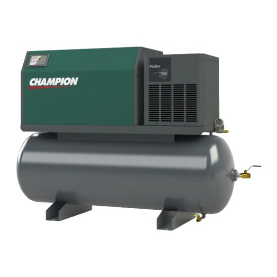
Authorized distributor service technicians are factory trained and skilled in compressor maintenance and repair. They are ready to respond and assist you by providing fast, expert maintenance and repair services. To contact Champion or locate your local distributor: Visit: www.championpneumatic.com... - Page 2 D6.D7.5-MANS Mar ’19 Quick Start 36” Unit [915mm] Nameplate Mechanical Installation Model No. Serial No. (Refer to Page 6) Unit voltage 18” 18” [458mm] [458mm] 18” [458mm] 18” [458mm] 18” [458mm] Note: Dimensions indicated are typical for all variations of D6-7.5 Series Units, ie base mounted, or horizontal.
- Page 3 D6.D7.5-MANS Mar ’19 Quick Start (cont’d) Unit Operation Shown below is the ‘CSC50’ Controller which regulates the operation of the Unit. It is used to start and stop the Unit, and it provides information as to system pressure, temperature, etc. Starting the Unit: Press the ‘Start’...
-
Page 4: Safety Precautions
D6.D7.5-MANS Mar ’19 Safety Precautions In order to operate the Compressor Unit safely and correctly, we have opted to use the following symbols to make you aware of important points. These points relate to user safety and preventing equipment problems. Please pay close attention to these sections. -
Page 5: Unpacking And Inspection
Shipments of Champion products are the property of the Consignee when the products leave our facility. Champion is not responsible for any damages or shortages caused to the product after it has left our shipping dock. - Page 6 D6.D7.5-MANS Mar ’19 Installation – Mechanical Moving of the Unit When moving the Air Compressor, the forklift or hand lift forks go under the Unit from the directions as indicated. When lifting from position ‘A’, use extended forks. Please be advised that, though care must be taken when moving all Units, extra care must be taken when positioning a vertical Compressor as they are top heavy.
- Page 7 D6.D7.5-MANS Mar ’19 Installation – Mechanical (cont’d) Shown below are items which assist in making a good installation. These are both intake and exhaust ductwork, helping the Unit to a) draw in clean outside air and b) exhaust the warmer air away from the Unit. The warmer air may be used, with the inclusion of a damper in the exhaust ducting, to warm the interior of the building during the colder months of the year.
-
Page 8: Lubrication
Oil level on a monthly basis. damage may result from use, however limited, without oil. Use only Champion lubricant. As well, do not mix Champion lubricant with any other lubricant. Subsequent Oil Changes Drain the existing oil from the Unit. (Please be... -
Page 9: Installation - Electrical
D6.D7.5-MANS Mar ’19 Installation - Electrical General Information It is your responsibility to ensure that the Compressor The sales drawing found at the back of this booklet Unit is electrically connected in a safe and correct indicates the amp rating for the Unit. This information manner. - Page 10 D6.D7.5-MANS Mar ’19 Installation – Electrical (cont’d) Do not attempt to operate the Unit without first checking whether there is oil in the Air End Reservoir. Add oil as required. Serious damage may result from use, however limited, without oil. Electrical Connection Bring power to Protective...
- Page 11 D6.D7.5-MANS Mar ’19 Motor Maintenance Instructions Cleaning To ensure that the Motor operates at optimum temperatures and provides years of trouble-free service, periodically clean the outside of the Motor Housing of any build-up of dust, etc. Though it is not anticipated that, if installed correctly and in a suitable environment, there should not be much build-up on the Motor, keeping the Housing clean will allow the Motor to operate more efficiently.
-
Page 12: Start-Up Procedures
D6.D7.5-MANS Mar ’19 Start-up Procedures Do not attempt to operate the Unit without first checking whether there is oil in the Air End Reservoir. Add oil as required. Serious damage may result from use, however limited, without oil. Initial Start-up 7) Open the Ball Valve slightly and allow the air 1) Remove the LH Side Access Panel, and to bleed from the Tank. -
Page 13: And Preventative Maintenance Schedule
Noted on the following pages are general Maintenance guidelines based on average working conditions. Should the Unit be worked under extreme conditions, please contact your Champion Distributor for further input. As well, all maintenance/service work must be carried out by a qualified Technician. - Page 14 Oil sample bottles are to be obtained from your local authorized Champion distributor. b) The Champion oil used in the maintenance schedule is rated as a 4000 hour oil. A complete Oil change must be done every 4000 hours of Unit operation, or every 12 months, whichever occurs first.
- Page 15 Separator, lubricate the Separator Gasket with build-up. Compressor Oil. 5) Install a new Air Filter (Champion Part Number 3) Hand tighten the new Air / Oil Separator snug ‘DSC-001569’), place the Element Top on the Filter, and fasten down with the Wing Nuts.
- Page 16 Cooler, Tubing, etc.) Fill the Oil Reservoir to the top of the Oil Fill Port as shown below. Do not under or overfill. See drawing below. Use only Champion lubricant. Oil Drain Port - 16 -...
- Page 17 D6.D7.5-MANS Mar ’19 Maintenance Procedures (cont’d) Adjusting the Drive Belts The tightening and loosening of the Drive Belts is done by way of moving the Air End horizontally either towards or away from the Motor. Units of Serial Numbers of ‘37622’ and Less Tension Adjusting Nut Bracket...
- Page 18 D6.D7.5-MANS Mar ’19 Maintenance Procedures (cont’d) Intake Valve Repair Kit The Intake Valve Assembly is located directly below the Intake Filter, and should be rebuilt after a maximum of 8,000 hours of Unit operation. There are two versions of intake valves used on D5 and D7.5 series air ends. ‘DSC-001712 Intake Valve Repair Kit can be used on both versions.
- Page 19 D6.D7.5-MANS Mar ’19 Maintenance Procedures (cont’d) Thermo Valve Repair Kit The Thermostatic Valve Assembly is located on the bottom of the Air End, and to the right of the Oil, and should be rebuilt after a maximum of 12,000 hours of Unit operation.
- Page 20 D6.D7.5-MANS Mar ’19 Maintenance Procedures (cont’d) Minimum Pressure Valve Repair Kit The Minimum Pressure Valve is located beside the Air Oil Separator, and a) acts to ensure there is a back-pressure of approx. 80 psi (5.5bar) to provide sufficient lubrication in the Air End and b) acts to stop compressed air from flowing backwards ie.
-
Page 21: Csc50' Controller
D6.D7.5-MANS Mar ’19 ‘CSC50’ Controller Description of Controller The ‘CSC50’ Controller is the ‘brains’ of the D6 and D7.5 series Rotary Screw Compressor Units. It monitors, enables, and indicates the various functions of the Unit. The Controller is comprised of two levels of access, segregated into: - Level 1 or ‘Operational Menu’: - allowing access to the most commonly used parameters - Level 2 or ‘Configuration Menu’:... - Page 22 D6.D7.5-MANS Mar ’19 ‘CSC50’ Controller (cont’d) The Controller has been fully programmed at the factory. Serious consequences could result should any of the parameters be adjusted by someone who is not familiar with the correct and safe operation of the Unit. Controller Display The Controller Display indicates a variety of useful items for both operating and troubleshooting the Unit.
- Page 23 The following values have been programmed into the ‘CSC50’ Controller. Do not adjust the values without first consulting with your Distributor or Champion. (Access is granted to these parameters by following the procedure as noted below at ‘Service Due Countdown Timer’).
-
Page 24: Common Compressor Faults
D6.D7.5-MANS Mar ’19 Common Compressor Faults Common Faults Noted below are the most common Faults experienced. ‘CSC50’ Alarms There is an issue with the Unit, but it will still operate. Code: Description: Most Common Items to Check: Solenoid not working, Intake Valve Orifice clogged, Transducer dirty or faulty, pressure changed A:2118 High Pressure incorrectly, alternate external pressure source... -
Page 25: Separator Filter And Refrigerated Air Dryer
D6.D7.5-MANS Mar ’19 Separator Filter and Refrigerated Air Dryer Your Unit may be equipped with a Separator Filter and an ‘ASD15’ (on ‘D6TD’ Units) or ‘ASD30’ (on ‘D7.5TD Units) Refrigerated Air Dryer Unit as indicated below. These items are located in the compressed air lines after the air is compressed but before it enters the Air Receiver. - Page 26 D6.D7.5-MANS Mar ’19 Separator Filter and Refrigerated Air Dryer (cont’d) Motors. Typical Dryer Operation The Dryer will operate as follows: Pressing the ‘On/Off’ Button for 3 seconds will start the Unit • There is a time delay of up to 2 minutes before the Refrigerant Compressor starts. •...
- Page 27 D6.D7.5-MANS Mar ’19 Separator Filter and Refrigerated Air Dryer (cont’d) Typical Separator Filter As previously noted, the Separator Filter is located between the Air End and the Refrigerated Dryer. It contains a 1 micron Separator Element which protects the Dryer Unit by removing liquids and solid particles 1 micron and larger.
-
Page 28: Trouble-Shooting Guide
Compressor Unit unless you are familiar with it, as there are many issues that may come into play, the most important being personal safety and the welfare of the Unit. Should you have any questions, or require servicing to your Unit, please contact your local Champion Distributor/Service Center. - Page 29 D6.D7.5-MANS Mar ’19 Trouble Shooting Guide (cont’d) Condition: Cause: Suggested Correction: B. No or Insufficient Air Flow. Air Filter is dirty. Replace the Air Filter. Oil Separator is blocked. Replace the Oil Separator. Intake Valve is faulty. Repair or replace the Intake Valve. Air leaks in the system.
- Page 30 D6.D7.5-MANS Mar ’19 Trouble Shooting Guide (cont’d) Condition: Cause: Suggested Correction: E. Intake Valve Leaks Oil Intake Valve Seal leaks. Repair using an Intake Valve Repair Kit. When Unit Stops. Intake Valve stuck in open position. Repair or replace the Intake Valve. Blowdown Solenoid not functioning.
-
Page 31: Warranty
COMPRESSOR PRODUCTS Standard Warranty Oil‐Lubricated Rotary Screw Packages D Series, DRS Series STANDARD WARRANTY Champion (the “Company”) warrants to each original retail purchaser (“Purchaser”) of its new products from the Company or its authorized distributor that such products are, at the time of delivery to the Purchaser, free of defects in material and workmanship. This Standard Warranty statement applies to compressors shipped after May 1 , 2015. STANDARD WARRANTY PERIOD The Company’s obligation under this warranty is limited to repairing or, at its option, replacing, during normal business hours at an authorized service facility of the Company, any part which in its judgment proved not to be as warranted within the applicable warranty period as follows. Regular maintenance in accordance with the service manual is required. Use of genuine Champion OEM parts and lubricants are highly recommended. If a component failure is deemed a result of using non‐genuine Champion parts and lubricants, warranty will not be allowed. COMPONENT STANDARD WARRANTY COVERAGE DETAILS 12 months from startup or 15 months from date of Package All components within the package, excluding normal wear items shipment to first purchaser, whichever occurs first Normal wearing items, such as shaft seals and inlet valve components, along with the servicing of these items is not covered under the warranty 12 months from startup or 15 months from date of Airend unless deemed as material or workmanship defects. Any disassembly or shipment to first purchaser, whichever occurs first partial disassembly of the airend, or failure to return the “unopened” airend per Company instructions, will be cause for denial of warranty. Electric 12 months from startup or 15 months from date of ... - Page 32 PREMIUM WARRANTY PLAN PERIOD Champion (the “Company”) shall warrant the components identified below to be free of defects in material and workmanship for the warranty period. Normal wearing components and servicing of these items is not covered under the premium warranty. The Company’s obligation under this warranty is limited to repairing or, at its option, replacing, during normal business hours at an authorized service facility of the Company, any part which in its sole judgment proved not to be as warranted within the applicable warranty period as follows.
- Page 33 Every 2000hrs or 6 months, whichever occurs first Participation in Champion’s oil analysis sampling program is required. An oil sample must be sent to our lubricant analysis laboratory every 2000 hours or every 6 months, whichever occurs first. Any recommendations detailed in the oil analysis report must be followed as outlined in the report.
- Page 36 MAINTENANCE KIT PART NUMBER DESCRIPTION QTY. DSC-002055 SHAFT SEAL KIT DSC-002053 AIR END 24V SS-23 3/8-16 X 3/4 HHCS B/M SS-1502 3/8" LOCKWASHER DSC-001540 AIR END MOUNTING ANGLE SS-1515 M10 HC LOCKWASHER MO-9025 MOTOR 5HP 230/60/1 MO-6407 MOTOR 5HP 200/60/3 MO-6435 MOTOR 5HP 230/460/60/3 MO-9033...
- Page 37 PART NUMBER DESCRIPTION QTY. DSC-002221 HEAT EXCHANGER DSC-001353 ADAPTER 1/2"NPT(M) - JIC 8(M) DSC-200 BONDED WASHER 1/2" BSPP DSC-001214 ADAPTER 1/2"BSPP - JIC 8 DSC-002476-CH AIR/OIL SEPARATOR FILTER DSC-002215 AIR INLET TUBE TIA-5200 SAFETY VALVE 200PSI DSC-001564 ADAPTER 1/4"BSPPM - 1/4"NPTF DSC-001968 COPPER SEALING RING 1/4"BSPP DSC-001572...
- Page 38 Encapsulated airend 1.2.1 Air inlet filter Intake valve 1.2.1 Venting orifice Solenoid valve - NO Air end Scavenge check valve Scavenge orifice Oil Filter Thermostatic valve Air/Oil separator 1.10 Minimum pressure valve 1.11 Air/Oil receiver Outlet minimum pressure valve Air connection (After minimum pressure valve) Safety valve connection Return from the oil cooler Outlet thermostatic valve (Inlet to the oil cooler)
- Page 39 POWER CIRCUIT SCHEMATIC FUSIBLE DISCONNECT BY CUSTOMER STARTER 1.75 X FULL LOAD CURRENT AMP MAX - EMERGENCY STOP - STARTER COIL - PRESSURE TRANSDUCER - ANTI-ROTATION SWITCH - SOLENOID - TEMPERATURE SENSOR - OVERLOAD RELAY RSS - REMOTE START/STOP (REFER TO REMOTE START INSTALLATION INSTRUCTIONS, DSC-002851) TRANSFORMER...
- Page 40 POWER CIRCUIT SCHEMATIC FUSIBLE DISCONNECT BY CUSTOMER 1.75 X FULL LOAD CURRENT AMP MAX STARTER - EMERGENCY STOP - STARTER COIL - PRESSURE TRANSDUCER - ANTI-ROTATION SWITCH - SOLENOID - TEMPERATURE SENSOR - OVERLOAD RELAY RSS - REMOTE START/STOP (REFER TO REMOTE START INSTALLATION INSTRUCTIONS, DSC-002851 ) TRANSFORMER...
Need help?
Do you have a question about the D6 Series and is the answer not in the manual?
Questions and answers