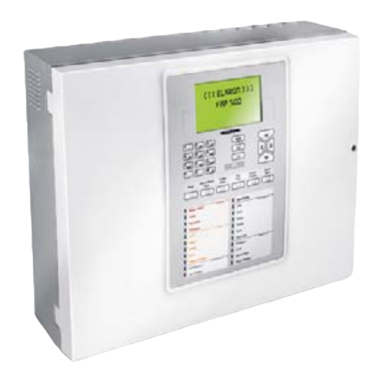
Elkron FAP54 User Manual
Multiprocessor modular control panel for fire detection
Hide thumbs
Also See for FAP54:
- Programming manual (152 pages) ,
- Installation manual (40 pages) ,
- User manual (28 pages)

Subscribe to Our Youtube Channel
Related Manuals for Elkron FAP54


Summary of Contents for Elkron FAP54
- Page 1 FAP54 Multiprocessor modular control panel for fire detection DS80SC61-001C LBT80096...
- Page 2 Elkron is a trademark of URMET S.p.A. All trademarks mentioned in this document belong to the corresponding owners. All rights reserved. The total or partial reproduction of this document is authorised only for installation purposes of the FAP54 System. Tel. +39 011.3986711 – Fax +39 011.3986703 www.elkron.com –...
-
Page 3: Table Of Contents
FIRST LEVEL OPERATIONS ............................. 11 INCLUDE/EXCLUDE PUSHBUTTON..........................12 KEYS AND INDICATORS FOR THE OPERATOR......................13 FAP54-01 KEYPAD LAYOUT............................. 15 FAP54-04/08/16 KEYPAD LAYOUT........................... 16 OPERATIONS TO BE CARRIED OUT IN CASE OF ALARM.................... 17 OPERATIONS TO BE CARRIED OUT IN CASE OF FAULT ..................... 17 APPENDIX .................................. -
Page 4: Operating Modes
1 OPERATING MODES The FAP54 control panel has two operating modes: scanning phase and programming phase. When FAP54 is powered on, the scanning phase will be always started and maintained until the installer or the user carries out an intervention. -
Page 5: Alarm Display
The events are displayed according to the following priority: • Zones in alarms (ZA) • General faults (GF) • Field faults (FF) • Exclusion (EX) • Group of points in alarm (GP) • Group of zones in alarm (GZ) • Maintenance (MN) •... -
Page 6: General Fault Display
4 GENERAL FAULT DISPLAY The display of a general fault depends on the type of event occurred and it usually allows the immediate recognition of the equipment or part of the control panel in faulty condition which can negatively affect the system operation. In any case, the display shows each event with all the data needed for the equipment identification (e.g. -
Page 7: Exclusion Display
6 EXCLUSION DISPLAY During the scanning phase it is possible to know the state of the active exclusions regarding the equipment connected with the control panel, the abstract entities (zones, groups), the devices and the detection lines. A few examples are reported below. Display of excluded device Circuit of excluded point Address of excluded point... -
Page 8: Maintenance Display
7 MAINTENANCE DISPLAY The display of a device requiring maintenance allows the immediate recognition of a smoke detector which needs to be replaced or cleaned as it is no longer reliable. Therefore, the display will show the information necessary to identify the device on the circuit. -
Page 9: Slave Control Panel Display
8 SLAVE CONTROL PANEL DISPLAY This section is valid only if the control panel is configured as a MASTER and it is connected to a network of SLAVE control panels. Any event occurring on a SLAVE control panel is notified to the MASTER control panel, which shows it by using two rows, according to the following rules: •... -
Page 10: Generic Events Display
NOTE - consider the following condition: • the panel is a MASTER and it is connected to one or more SLAVE panels • the MASTER contains local events ( (there are folders other than SP which are not empty) • the SP folder is not empty and the events are all generated by the same SLAVE panel •... -
Page 11: First Level Operations
11 FIRST LEVEL OPERATIONS ACK: by pressing ACK the control panel buzzer will be silenced and the event displayed will be acknowledged. ALARM SILENCING: by pressing SILENCE / RESTART SIREN the active device (plates or sirens) sound will be temporarily stopped. The yellow LED associated with the SILENCED SIREN will turn on. To restore the sound, press again the SILENCE / RESTART SIREN. -
Page 12: Include/Exclude Pushbutton
12 INCLUDE/EXCLUDE PUSHBUTTON When the control panel is monitoring the field it is possible to include or exclude circuits, zones, groups, points, functions or equipment connected to the control panel without switching over to the programming phase. The access to this menu requires the level 2 password, if enabled. By pressing INCLUDE/EXCLUDE, the following menu will be displayed: [1] INCLUDE/EXCLUDE CIRCUIT [2] INCLUDE/EXCLUDE POINTS/ZONES... -
Page 13: Keys And Indicators For The Operator
13 KEYS AND INDICATORS FOR THE OPERATOR FUNCTION This key must be pressed to acknowledge the events (alarms, faults, maintenance) detected by the control panel. This key starts the “Global Reset” procedure. RESET Whenever the user presses this key, an event is stored in the event log and, if the passwords are enabled, the level 2 password is required. - Page 14 INDICATOR COLOR FUNCTION Blinking: the control panel is in alarm condition and the siren output is not active FIRE ALARM Fixed ON: the control panel is in alarm condition and the siren output is active MASTER ALARM When turned ON, a general alarm condition has occurred Blinking: the modem is attempting to setup a call Steady ON: the modem connection is active MODEM ACTIVE...
-
Page 15: Fap54-01 Keypad Layout
14 FAP54-01 KEYPAD LAYOUT FAP User... -
Page 16: Fap54-04/08/16 Keypad Layout
15 FAP54-04/08/16 KEYPAD LAYOUT FAP User... -
Page 17: Operations To Be Carried Out In Case Of Alarm
16 OPERATIONS TO BE CARRIED OUT IN CASE OF ALARM 1. Press ACK. 2. Read the point in alarm on the display. 3. Go and check the possible alarm on the field. If no problems are detected or no real danger exists press RESET. -
Page 18: Appendix
18 APPENDIX 18.1 APPENDIX 1 – ERROR CODES FOR FAULT OF POINTS If a point undergoes a fault, this fault is detected by the control panel during the scanning phase and the user is notified about it with a message: FAULT ZXXX CYY PZZZ TT FWWW... - Page 19 The following table contains the point error codes and the relevant explanation. Code Fault Smoke/heat detector: internal fault of the optical section Smoke/heat detector: internal fault of the optical section (signal less than the fault threshold) Internal fault of the temperature detection section Smoke detector: error at the end of the optical calibration procedure Smoke detector: optical calibration is missing because of out of range temperature Internal fault: non volatile memory access error...
-
Page 20: Appendix 2 - Fault Codes For Line Circuit Cards
Code memory corrupted Non volatile memory corrupted (1) (1) Please, contact the ELKRON Customer Service. 18.3 APPENDIX 3 – FAULT CODES FOR THE COMMAND AND CONTROL MODULE If the Command & Control module undergoes a fault during the scanning phase, the user is notified with this message: FAULT C&C MODULE... -
Page 21: Appendix 4 - Fault Codes For The Lcd Annunciators
18.4 APPENDIX 4 – FAULT CODES FOR THE LCD ANNUNCIATORS If an LCD Annunciator connected to and recognized by the control panel undergoes a fault during the scanning phase, the user is notified with the following message: FAULT LCD ANNUNCIATOR XX (YY) NAME OF THE LCD ANNUNCIATOR XX = address of the LCD annunciator affected by the fault YY = fault code... -
Page 22: Appendix 6 - System Error Codes
BMP3, BMP2, BMP1, BMP0 = bitmap of the supervision mask (32 bit) (***) This fault occurs when the Ethernet configuration parameters are wrong. To solve this issue, reconfigure these parameters from the relevant programming menu. (1) Please, contact the ELKRON Customer Service. FAP User... -
Page 23: Appendix 7 - Fault Codes For Slave Control Panels
18.7 APPENDIX 7 – FAULT CODES FOR SLAVE CONTROL PANELS If a slave control panel undergoes a fault during the scanning phase, the user is notified with the following message: FAULT SLAVE PANEL XXX (YY) NAME OF THE SLAVE CONTROL PANEL XXX = address of the slave control panel affected by the fault = fault code The table below reports the fault codes along with the relevant explanation:... -
Page 24: Appendix 9 - Point Types
18.9 APPENDIX 9 – POINT TYPES The following table shows the shortened strings related to the point types and the relevant explanation. These strings can be found in the messages of alarm events, faults and exclusions related to the point. Point type Meaning (shortened) -
Page 25: Appendix 12 - Zone Types
Printer module: non volatile memory access error Printer in fault (generic error) (1) Please, contact the ELKRON Customer Service. 18.14 APPENDIX 14 – PS2 KEYBOARD MAPPING The table below shows the list of the PS2 keys used and their mapping with the correspondent key in the internal keyboard. -
Page 26: Appendix 15 - Error Codes For Circuit Fault (Communication Error)
18.15 APPENDIX 15 – ERROR CODES FOR CIRCUIT FAULT (COMMUNICATION ERROR) The table below reports the error codes relevant to the circuit fault notified with the following message: FAULT CIRCUIT XX COMM. ERR. YYY DZZZ Where: = circuit number = error code (see the table below) ZZZ = address of the point Code Meaning... - Page 27 FAP User...
- Page 28 ELKRON is a trademark of ELKRON URMET S.p.A. Tel. +39 011.3986711 - Fax +39 011.3986703 Via Bologna, 188/C - 10154 Torino (TO) – Italy Milano:Tel. +39 02.334491- Fax +39 02.33449213 www.urmet.com www.elkron.com – mail to: info@elkron.it FAP User...
Need help?
Do you have a question about the FAP54 and is the answer not in the manual?
Questions and answers