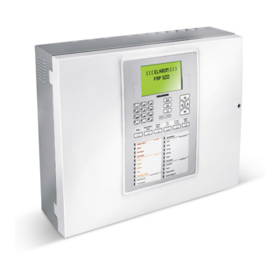
Elkron FAP54 User Manual
Multiprocessor modular control panel for fire detection
Hide thumbs
Also See for FAP54:
- Programming manual (152 pages) ,
- Installation manual (40 pages) ,
- User manual (28 pages)
Table of Contents
Advertisement
Quick Links
Advertisement
Table of Contents

Subscribe to Our Youtube Channel
Related Manuals for Elkron FAP54


Summary of Contents for Elkron FAP54
- Page 1 FAP54 Multiprocessor modular control panel for fire detection Through the following QR Code, it is possible to download the eventual new version of the manual. http://qrcode.urmet.com/default.aspx?sito= Elkron&prodElkron=157445&lingua=en 00 51 DS80SC4A-006 LBT81075...
- Page 2 Elkron is a trademark of URMET S.p.A. All trademarks mentioned in this document belong to the corresponding owners. All rights reserved. The total or partial reproduction of this document is authorised only for installation purposes of the FAP54 System. Tel. +39 011.3986711 – Fax +39 011.3986703 www.elkron.com –...
-
Page 3: Table Of Contents
TABLE OF CONTENTS OPERATING MODES .................................. 4 SCANNING PHASE ..................................4 ALARM DISPLAY ..................................5 GENERAL FAULT DISPLAY ............................... 6 FIELD FAULT DISPLAY ................................6 EXCLUSION DISPLAY ................................7 MAINTENANCE DISPLAY ................................8 SLAVE CONTROL PANEL DISPLAY ............................8 GENERIC EVENTS DISPLAY ..............................9 CONTROL PANEL FUNCTIONAL STATES ........................ -
Page 4: Operating Modes
1 OPERATING MODES The FAP54 control panel has two operating modes: scanning phase and programming phase. When FAP54 is powered on, the scanning phase will be always started and maintained until the installer or the user carries out an intervention. -
Page 5: Alarm Display
3 ALARM DISPLAY Display of Zone Alarm generated by device associated with zone Device attributes Zone delay (see appendix) Device address in alarm No. of zone in alarm Alarm event indicator >ZA001 GF000 Z110 D00 C01 P018 TP Q Axyy FF000 KITCHEN DETECTOR EX000... -
Page 6: General Fault Display
4 GENERAL FAULT DISPLAY The display of a general fault depends on the type of event occurred and it usually allows the immediate recognition of the equipment or part of the control panel in faulty condition which can negatively affect the system operation. In any case, the display shows each event with all the data needed for the equipment identification (e.g. -
Page 7: Exclusion Display
6 EXCLUSION DISPLAY During the scanning phase it is possible to know the state of the active exclusions regarding the equipment connected with the control panel, the abstract entities (zones, groups), the devices and the detection lines. A few examples are reported below. Display of excluded device Circuit of device Address of device... -
Page 8: Maintenance Display
7 MAINTENANCE DISPLAY The display of a device requiring maintenance allows the immediate recognition of a smoke detector which needs to be replaced or cleaned as it is no longer reliable. Therefore, the display will show the information necessary to identify the device on the circuit. Circuit of device Address of device Relevant zone... -
Page 9: Generic Events Display
If a SLAVE control panel is affected by at least one exclusion, the MASTER control panel shows a message like this: SLAVE 050 HANGAR GD000 ACTIVE EXCLUSIONS 007 GZ000 MN000 >SP001 This message indicates the number of elements currently excluded on the SLAVE control panel (in the example, there are 7 active exclusions on the SLAVE control panel). -
Page 10: Control Panel Functional States
10 CONTROL PANEL FUNCTIONAL STATES NORMAL: all the indicators are normally OFF but the following LEDs: AC: steady green if the control panel is powered on by the main power, blinking green if the control panel is powered on by batteries ... -
Page 11: First Level Operations
11 FIRST LEVEL OPERATIONS ACK: by pressing ACK the control panel buzzer will be silenced and the event displayed will be acknowledged. ALARM SILENCING: by pressing SILENCE / RESTART SIREN the active device (plates or sirens) sound will be temporarily stopped. The yellow LED associated with the SILENCED SIREN will turn on. -
Page 12: Include/Exclude Button
12 INCLUDE/EXCLUDE BUTTON When the control panel is monitoring the field it is possible to include or exclude circuits, zones, groups, devices, functions or equipment connected to the control panel without switching over to the programming phase. The access to this menu requires the advanced level 2 password, if enabled. By pressing INCLUDE/EXCLUDE, the following menu will be displayed: [1] INCLUDE/EXCLUDE CIRCUIT [2] INCLUDE/EXCLUDE DEVICES/ZONES... -
Page 13: Keys And Indicators For The Operator
13 KEYS AND INDICATORS FOR THE OPERATOR FUNCTION This key must be pressed to acknowledge the events (alarms, faults, maintenance) ( ) detected by the control panel. This key starts the “General Reset” procedure. RESET Whenever the user presses this key, an event is stored in the event log and, if the passwords are enabled, the level 2 password is required. - Page 14 INDICATOR COLOR FUNCTION Blinking: the control panel is in alarm condition and the siren output is not active. FIRE ALARM Fixed ON: the control panel is in alarm condition and the siren output is active. MASTER ALARM When turned ON, a general alarm condition has occurred. With communicator inserted: Blinking: ongoing alarm transmission from E type communicator towards ACTIVE...
-
Page 15: Fap541 Keypad Layout
14 FAP541 KEYPAD LAYOUT Silence/Rearm Increase Skip Include/ Master Reset Siren Delay Alarm Delay Exclude ALARMS Main/Battery Fire Alarm EXCLUSIONS Line Master Alarm Active Communicator Zone FAULTS Group Communicator Status General Device Siren System Battery Actuators GENERAL Siren Exclusion Earth Remote Device MAINTENANCE Maintenance... -
Page 16: Fap544/8/16 Keypad Layout
15 FAP544/8/16 KEYPAD LAYOUT Silence/Rearm Increase Skip Include/ Master Reset Siren Delay Alarm Delay Exclude ALARMS Fire Alarm Main/Battery EXCLUSIONS Master Alarm Line Active Communicator Zone FAULTS Communicator Status Group General Device System Siren Battery Actuators GENERAL Siren Exclusion Earth Remote Device MAINTENANCE Maintenance... -
Page 17: Operations To Be Carried Out In Case Of Alarm
16 OPERATIONS TO BE CARRIED OUT IN CASE OF ALARM 1. Press ACK. 2. Read the device in alarm on the display. 3. Go and check the possible alarm on the field. If no problems are detected or no real danger exists press RESET. -
Page 18: Appendix
18 APPENDIX 18.1 APPENDIX 1 – ERROR CODES FOR FAULT OF DEVICES If a device undergoes a fault, this fault is detected by the control panel during the scanning phase and the user is notified about it with a message: FAULT ZXXX CYY PZZZ TT FWWW... - Page 19 The following table contains the device error codes and the relevant explanation. Code Fault Smoke/heat detector: internal fault of the optical section. Smoke/heat detector: internal fault of the optical section (signal less than the fault threshold). Internal fault of the temperature detection section. Smoke detector: error at the end of the optical calibration procedure.
-
Page 20: Appendix 2 - Fault Codes For Line Circuit Cards
Code memory corrupted. Non volatile memory corrupted (1). (1) Please, contact the ELKRON Customer Service. 18.3 APPENDIX 3 – FAULT CODES FOR THE COMMAND AND CONTROL MODULE If the Command & Control module undergoes a fault during the scanning phase, the user is notified with this message: FAULT C&C MODULE... -
Page 21: Appendix 4 - Fault Codes For The Lcd Annunciators
Fault reported by the communicator module: no communication with control panel. Fault reported by the communicator module: Reset cause (not meaningful for the module reset. user): please contact ELKRON service. No communication with the communicator module (lifetime timeout). FAP User... -
Page 22: Appendix 6 - System Error Codes
BMP3, BMP2, BMP1, BMP0 = bitmap of the supervision mask (32 bit) (***) This fault occurs when the Ethernet configuration parameters are wrong. To solve this issue, reconfigure these parameters from the relevant programming menu. (1) Please, contact the ELKRON Customer Service. FAP User... -
Page 23: Appendix 7 - Fault Codes For Slave Control Panels
18.7 APPENDIX 7 – FAULT CODES FOR SLAVE CONTROL PANELS If a slave control panel undergoes a fault during the scanning phase, the user is notified with the following message: FAULT SLAVE PANEL XXX (YY) NAME OF THE SLAVE CONTROL PANEL XXX = address of the slave control panel affected by the fault = fault code The table below reports the fault codes along with the relevant explanation:... -
Page 24: Appendix 9 - Device Types
18.9 APPENDIX 9 – DEVICE TYPES The following table shows the shortened strings related to the device types and the relevant explanation. These strings can be found in the messages of alarm events, faults and exclusions related to the device. Device type Meaning (shortened) -
Page 25: Appendix 13 - Error Codes For Printer Module
Printer module: non volatile memory access error. Printer in fault (generic error). (1) Please, contact the ELKRON Customer Service. 18.14 APPENDIX 14 – PS2 KEYBOARD MAPPING The table below shows the list of the PS2 keys used and their mapping with the corresponding key in the internal keyboard. -
Page 26: Appendix 15 - Error Codes For Circuit Fault (Communication Error)
18.15 APPENDIX 15 – ERROR CODES FOR CIRCUIT FAULT (COMMUNICATION ERROR) The table below reports the error codes relevant to the circuit fault notified with the following message: FAULT CIRCUIT XX COMM. ERR. YYY DZZZ Where: = circuit number = error code (see the table below) ZZZ = address of the device Code Meaning... - Page 27 DIRECTIVE 2012/19/EU OF THE EUROPEAN PARLIAMENT AND OF THE COUNCIL of 4 July 2012 on waste electrical and electronic equipment (WEEE) The symbol of the crossed-out wheeled bin on the product or on its packaging indicates that this product must not be disposed of with your other household waste. Instead, it is your responsibility to dispose of your waste equipment by handing it over to a designated collection point for the recycling of waste electrical and electronic equipment.
- Page 28 ELKRON URMET S.p.A. Tel. +39 011.3986711 - Fax +39 011.3986703 Via Bologna, 188/C - 10154 Torino (TO) – Italy Milano:Tel. +39 02.334491- Fax +39 02.33449213 www.urmet.com www.elkron.com – mail to: info@elkron.it MADE IN ITALY FAP User...
Need help?
Do you have a question about the FAP54 and is the answer not in the manual?
Questions and answers