
Subscribe to Our Youtube Channel
Related Manuals for Elkron C402


Summary of Contents for Elkron C402
- Page 1 C402 / C404 Conventional Fire Detection Control Panel with 2 and 4 zones 0051 DS80SC80-003D LBT80808 1/28 Installazione MP508...
- Page 2 In this manual, you may find references and information about products (hardware or software) or services not commercialized yet. These references and information do not imply that the company intends to commercialize these products and services. Elkron is a trademark of URMET S.p.A. All trademarks mentioned in this document belong to the corresponding owners.
-
Page 3: Table Of Contents
SUPERVISED SIREN OUTPUT ............................22 FIELD OUTPUT................................... 22 FAULT RELAY OUTPUT ..............................22 DISTRIBUTION OF CONSUMPTIONS ..........................22 MR402, MR404 OPTIONAL MODULES - OUTPUT WITH RELAY ..................22 8.10 MECHANICAL - ENVIRONMENTAL CONDITIONS ....................... 23 ELECTRICAL CONNECTIONS ..............................25 Installation-Programming C402-C404... -
Page 4: General Description
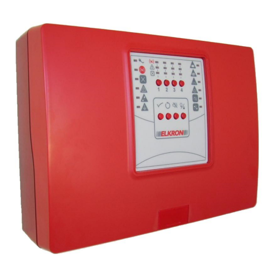
1.1 INTRODUCTION The fire detection control panels C402 and C404 control respectively up to 2 and 4 independent zones with a maximum of 32 devices per zone. Each circuit is considered as an zone and can be included or excluded via a keypad command. -
Page 5: General Safety Measures
Do not try to modify the wiring or connectors of the batteries. These operations can cause injuries. 2.1.4 Battery disposal The lead batteries contain harmful substances! When the battery life cycle finishes, they must not be disposed of with ordinary waste. Batteries must be taken to an authorized waste recycling and disposal centre. Installation-Programming C402-C404... -
Page 6: Safety Of The Product
2.3 SPECIAL PRECAUTIONS Strictly follow the order of the installation and connection instructions described in this manual. Verify the indications reported on the identification plate: they must correspond to your electrical power supply and to the power consumption. Installation-Programming C402-C404... -
Page 7: Installation And Connections
3 INSTALLATION AND CONNECTIONS 3.1 ITEMS INCLUDED The following components are included with the product: • 2 resistors of 3300Ω for detection circuits termination (for C402) • 4 resistors of 3300Ω for detection circuits termination (for C404) • 1 resistor of 3300Ω for siren output termination •... -
Page 8: Power Supply Unit Terminal Blocks
26.4V negative output (connection already performed – do not modify) 26.4V positive output (connection already performed – do not modify) When the wiring is finished, insert the lid that covers the terminals. See Figure 2. Figure 2 – Closing of the lid that covers the terminals Installation-Programming C402-C404... -
Page 9: Control Panel Card Terminal Boards
Earth connection for detection circuits cable shield (*) Detection circuit 4 (*) positive output - L4 Detection circuit 4 (*) negative output (*) there is no terminal in the C402 version. “Power” terminals Earth connection Power supply negative Power supply positive... -
Page 10: Fuses And Jumpers
The two batteries must be installed inside the control panel and they must be connected in series, observing the polarity as in figure. For connecting the batteries use the supplied cables and do not modify the existing cabling. Batteries replacement must be performed only by qualified personnel. Figure 4 – Placement and connection of batteries Installation-Programming C402-C404... -
Page 11: Installation Of The Optional Relay Card
3.4 INSTALLATION OF THE OPTIONAL RELAY CARD To install the optional module MR402 (for C402) or MR404 (for C404), proceed as follows: • Switch off the control panel by acting on the disconnection switch, then open the container of the control panel by removing the front cover and disconnecting the positive terminal of the batteries. -
Page 12: Mr402 - Mr404 Module Of The Terminal Board
Alarm zone 3 relay output – common contact (*) Alarm zone 4 relay output – normally closed contact (*) Alarm zone 4 relay output – normally open contact (*) Alarm zone 4 relay output – common contact (*) (*) terminal not available in the MR402 module. Installation-Programming C402-C404... -
Page 13: System Start-Up
If there are fault indications, check that: • The circuit is not in short circuit • The polarity of the circuit and the devices is correct • The devices installed do not have excessive consumption • The end of line resistor has been connected Installation-Programming C402-C404... -
Page 14: Commands And Indicators
3 is entered. corresponding detection circuit is not power supplied. Includes or excludes the operation of During password entry procedure, zone 4. When the zone is excluded, the number 4 is entered. corresponding detection circuit is not power supplied. Installation-Programming C402-C404... -
Page 15: Indicator Lights (Leds)
(open circuit) circuit Zone 1 ÷ Zone N Zone 1 ÷ Zone N Non-excluded zone Excluded zone N = 2 (for C402), 4 (for C404) Installation-Programming C402-C404... -
Page 16: Signalling Outputs And Relays
The zone goes to alarm condition because of an alarm coming from two or more devices (zone programmed in double knock mode) On the optional modules MR402 and MR404, there is also an SPDT form C – dry contact relay output that signals an alarm condition of any zone of the control panel. Installation-Programming C402-C404... -
Page 17: Access Level
This deactivates the buzzer. When new alarms or faults are verified, the buzzer will be activated again. When the indicator is off, the control panel is at access level 1; when the control panel is power supplied, access level 1 is activated. Installation-Programming C402-C404... -
Page 18: Access Level 2
When a zone is excluded, the corresponding detection circuit is not power supplied. When the intervention is completed, it is recommended to restore the control panel to its regular condition of operation with access level 1, pressing the key and keeping it pressed until the indicator turns off. Installation-Programming C402-C404... -
Page 19: Programming
The operating mode of every zone is saved in the non-volatile memory of the control panel. The information in this memory cannot be lost when the control panel is not power supplied. Installation-Programming C402-C404... -
Page 20: Level 2 Password
The control panel has a default password from the factory reported in the table below. It is recommended to change the password and write it down in the appropriate “user” spaces. Password Number 1 Number 2 Number 3 Number 4 Factory User Installation-Programming C402-C404... -
Page 21: Technical Specifications
Recharging current with discharge batteries 300mA nominal Current drawn by the control panel in normal operative conditions 80mA 120mA (C402) Max current drawn only by the card of the control panel 140mA (C404) 8.4 BATTERIES Two rechargeable lead batteries must be connected in series inside the control panel. -
Page 22: Supervised Siren Output
500mA (C404) 550mA (C402) Available current at the supervised siren output 500mA (C404) Available current at the detection circuits for the 80mA (C402 – 2 detection circuits) conventional detectors 160mA (C404 – 4 detection circuits) Available current for batteries recharge 300mA 8.9 MR402, MR404 OPTIONAL MODULES - OUTPUT WITH RELAY... -
Page 23: Mechanical - Environmental Conditions
8.10 MECHANICAL - ENVIRONMENTAL CONDITIONS Figure 7 – Dimensions Installation-Programming C402-C404... - Page 24 CAT II In compliance with standards EN54-2: 1997 + A1: 2006 EN54-4: 1997 + A1: 2002 + A2: 2006 Conventional fire detection control panel C402 - ELKRON 0051-CPR-0338 DoP n. 0051-CPR-0338 Conventional fire detection control panel C404 - ELKRON 0051-CPR-0337 DoP n.
-
Page 25: Electrical Connections
RESISTOR SIR- SIREN / VISUAL SIREN / VISUAL MODULO SONG54 SIREN / VISUAL Figure 9 - Examples of connections of the siren output Check, according to the siren/plate used, which of the two connection types must be adopted. Installation-Programming C402-C404... - Page 26 DETECTION CIRCUIT C. PANEL (+) (-) CONVENTIONAL DETECTION CIRCUIT CONVENTIONAL DETECTOR LAST CONVENTIONAL DETECTOR 3300 END OF LINE RESITOR Figure 10 - Connection of the devices to the detection circuit Installation-Programming C402-C404...
- Page 27 Installation-Programming C402-C404...
- Page 28 ELKRON ELKRON is a trademark of URMET S.p.A. Tel. +39 011.3986711 - Fax +39 011.3986703 Via Bologna, 188/C - 10154 Torino (TO) – Italy Milano: Tel. +39 02.334491- Fax +39 02.33449213 www.urmet.com www.elkron.com – mail to: info@elkron.it MADE IN ITALY...
Need help?
Do you have a question about the C402 and is the answer not in the manual?
Questions and answers