Elkron FAP54 Programming Manual
Multiprocessor modular control panel for fire detection
Hide thumbs
Also See for FAP54:
- Programming manual (152 pages) ,
- Installation manual (40 pages) ,
- User manual (28 pages)
Table of Contents
Advertisement
Quick Links
Download this manual
See also:
User Manual
Advertisement
Table of Contents

Subscribe to Our Youtube Channel
Related Manuals for Elkron FAP54


Summary of Contents for Elkron FAP54
- Page 1 FAP54 Multiprocessor modular control panel for fire detection DS80SC61-003B LBT80102 1/144 FAP54...
- Page 2 All information included in this document has been collected and carefully verified; nevertheless Elkron S.p.A. cannot be held responsible for possible mistakes and omissions. Elkron S.p.A. reserves the right to modify or improve at any time the products described in this manual and without notice.
-
Page 3: Table Of Contents
USER’S INFORMATION DISPLAY......................19 2.1.9 ACQUISITION OF ALARM, FAULT OR MAINTENANCE EVENT ............. 19 2.1.10 GLOBAL RESET ............................19 2.1.11 PROGRAMMING PHASE ........................... 19 FAP54 - MODULAR STRUCTURE....................20 EMERGENCY OPERATION ......................21 INDICATORS, KEYS, RELAYS, JUMPERS ...................21 2.4.1 FRONT SIDE INDICATORS ........................21 2.4.2... - Page 4 READ REMOTE DEVICE ........................... 77 3.7.3 CONFIGURE LOCAL DEVICE ........................79 3.7.3.1 CONFIGURE IO MODULE (SINGLE MODULE) 3.7.3.2 CONFIGURE IO MODULE (MULTIPLE MODULE) 3.7.3.3 CONFIGURE OUTPUT MODULE (OM) 3.7.3.4 CONFIGURE LATCH INPUT MODULE (LI) 3.7.3.5 CONFIGURE PULSE INPUT MODULE (PI) 4/144 FAP54...
- Page 5 4.7.1 ZONE TEST .............................. 124 4.7.2 LAMP TEST .............................. 125 4.7.3 POINT TEST ............................. 125 4.7.3.1 START POINT TEST 4.7.3.2 STOP POINT TEST 4.7.3.3 VIEW TEST DATA 4.7.3.4 VIEW ALARM DATA FW VERSIONS ..........................129 SYSTEM TEST ........................130 5/144 FAP54...
- Page 6 8.11 APPENDIX 11 – QUALIFIER OF POINT ATTRIBUTES ...............142 8.12 APPENDIX 12 – ALARM TYPES ....................142 8.13 APPENDIX 13 – ZONE TYPES .....................142 8.14 APPENDIX 14 – ERROR CODES FOR PRINTER MODULE ............143 8.15 APPENDIX 15: PS2 KEYBOARD MAPPING................143 6/144 FAP54...
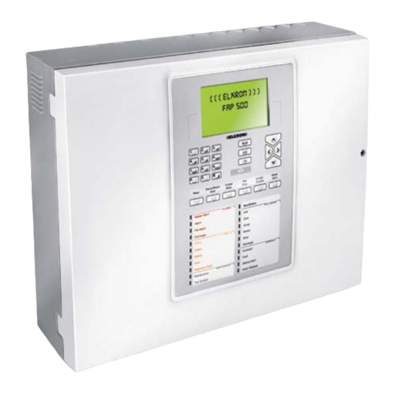
- Page 7 General description FAP54 is a modular control panel with a basic configuration, but its peripherals and functions can be further expanded. The control panel has 2 loops which can be increased to 4 and it can be interfaced with the outer world (PC, MODEM, LCD ANNUNCIATORS, LAN).
-
Page 8: Introduction
When the sum of the alarm point weights in the same zone is equal to or higher than the weight of the zone, the control panel enables the zone timer. When this timer expires, the control panel activates the siren output. 8/144 FAP54... -
Page 9: Basic Concepts
(zones, groups of points, groups of zones) which make up a complex control and surveillance system. Therefore, it is necessary to briefly analyze the elements making up a fire system to better understand the performances of FAP54 control panel. DETECTORS, MANUAL BUTTONS AND OUTPUT MODULES These points, installed on the detection lines, are subdivided into two categories: •... -
Page 10: Detection Lines And Control Panel
As a result, the output modules operate other devices for managing and/or signalling the alarm condition (light plates, sirens,…). The points which can be connected to the detection lines of FAP54 control panel are the following: DEVICE... -
Page 11: Group Of Points
Each detector can be associated with as many groups of points as the user wants at the same time. Therefore, different groups can share detectors. FAP54 control panel provides the user with 240 groups of points. It is possible to associate up to 50 detectors with each group of points. -
Page 12: Operating Modes Of Zones And Groups
12/144 FAP54... - Page 13 • Force the immediate expiration of the timer through the SKIP DELAY key on the control panel keypad. • Assign a zero value to the timer through the “Clear delay” function in the case of manual buttons and input modules provided with this functionality. 13/144 FAP54...
-
Page 14: Operating Modes
2 OPERATING MODES The FAP54 control panel has two operating modes: scanning phase and programming phase. When FAP54 is powered on, the scanning phase will be always started and maintained until the installer or the user carries out an intervention. -
Page 15: Alarm Display
Point type (see appendix) Display of alarm of group of zones generated by an associated zone Group delay Zone in alarm Group number Alarm event indicator G025 D00 Z033 GP000 BOILER ROOM >GZ001 MN000 SP000 Zone name 15/144 FAP54... -
Page 16: General Fault Display
In any case, a self-explaining message will be displayed. Below is reported an example of a field fault of type “short circuit” affecting circuit 1. Nr. of faulty circuit FAULT CIRCUIT 01 ZA000 SHORT CIRCUIT GF000 >FF001 Type of fault EX000 16/144 FAP54... -
Page 17: Exclusion Display
Therefore, the display will show the information necessary to identify the device on the circuit. Circuit of detector Address of detector under maintenance under maintenance Relevant zone MAINT. Z020 C01 P018 SM GP000 KITCHEN DETECTOR GZ000 >MN001 SP000 Detector name Type of detector 17/144 FAP54... -
Page 18: Slave Control Panel Display
The event log of the SLAVE control panel can be accessed directly from the MASTER control panel’s display. In order to do this, it is necessary to view any event of the SLAVE control panel of interest in the MASTER control panel’s display and then press OK. 18/144 FAP54... -
Page 19: Generic Events Display
2.1.8 USER’S INFORMATION DISPLAY In FAP54-4, FAP54-8 and FAP 54-16, it is possible to display two user messages, each one spread over 4 lines rather than the ELKRON logo. These messages must be explicitly programmed by the user via PC in order to be displayed (the ELKRON logo will be shown in the bottom part of the display until these user messages are programmed). -
Page 20: Fap54 - Modular Structure
FAP54 - MODULAR STRUCTURE FAP54 is a fire detection control panel with a completely modular structure which makes it possible to meet all field requirements also in the event of further system expansion. To meet these needs, FAP54 consists of different internal modules which can be “added” or “removed”. Below is reported a list of the modules making up FAP54 with a description of each single one: •... -
Page 21: Emergency Operation
EMERGENCY OPERATION The modular structure of FAP54 allows the complete control of the detection field also if the CPU board is faulty. In this case, as a result of the smart circuit modules, both the monitoring of the field and the notification of alarms are ensured through the relays and alarm indicators. -
Page 22: Keys (Tot 26)
Key confirming the data entry. Keypad Alphanumeric keypad with 12 keys for input of digits/characters. ∨ ∧, <, > Directional keys. 22/144 FAP54... -
Page 23: Outputs And Relays
This relay is activated also in case of faulty CPU board. 2.4.4 JUMPERS The FAP54 control panel is equipped with a few jumpers which enable functions such as the control panel programming via PC or backlight steady ON. For detailed information, please refer to the installation manual. -
Page 24: Master And Slave Control Panels (Optional)
MASTER AND SLAVE CONTROL PANELS (OPTIONAL) With FAP54 control panel it is possible to connect up to 32 SLAVE control panels to a MASTER control panel. The MASTER control panels will notify to the user any alarm/fault/maintenance events occurring in the SLAVE control panels connected with it. -
Page 25: Control Panel Programming
Power on the control panel, wait until it enters the scanning phase, then download the configuration from the personal computer to the control panel. Check the system functions: make sure there is a correct association between points and actions in case of alarm. Save the final configuration, if changed, on the personal computer. 25/144 FAP54... -
Page 26: Menu Prog- Control Panel Programming
[7] CONFIGURE POINTS Use this option to read or program the field point parameters inside the point. [8] MISCELLANEOUS Use this option to access other control panel programming options. To return to the previous menu screen press ESC. 26/144 FAP54... -
Page 27: Circuit
CIRCUIT 5: EXCLUDED CIRCUIT 6: OPEN CIRCUIT 7: ------ ∨ CIRCUIT 8: ------ After selecting the configuration of each circuit, press OK to pass to the selection of the addressing mode: [1] AUTO-ADDRESSED MODE [2] PRE-CONFIGURED MODE [3] UPDATE 27/144 FAP54... - Page 28 Circuit 5: remarks similar to line 2 Circuit 6, in open mode, has not been initialized correctly because of a line error … Circuit 15 is excluded Circuit 16, in open mode, has not been initialized correctly because of a procedure error. 28/144 FAP54...
-
Page 29: Configure Single Circuit
First, the user is asked to enter the number of the circuit to be initialized: CIRCUIT: After entering the circuit number and confirming it with OK, the user is asked for the type of configuration [1] SET SINGLE CIRCUIT IN LOOP MODE [2] SET SINGLE CIRCUIT IN OPEN MODE 29/144 FAP54... - Page 30 Type “ER” refers to devices with problems of communication with the control panel or to devices with duplicated addresses. 30/144 FAP54...
- Page 31 XXX/PI XXX/XS XXX/TB XXX/CI XXX/IS XXX/ER XXX/?? By pressing ESC the configuration is cancelled (in such a case, an empty configuration will be stored in the module), while by pressing OK the new configuration is confirmed and stored. 31/144 FAP54...
- Page 32 The same operations will be carried out on the modules where the procedure has been terminated incorrectly. 32/144 FAP54...
-
Page 33: Manual Circuit Configuration
It is possible to change the type of device on the detection line, even if physically it is different from the programmed device. It is not possible to change the type of device if it is excluded. 33/144 FAP54... -
Page 34: Include/Exclude
[7] SEARCH OPEN LOOP 3.1.5.1 POINT VERIFICATION The user shall specify and confirm with OK the circuit where the devices to be checked are located. CIRCUIT: The circuit type will be displayed (loop or open). CIRCUIT: XX CONFIGURATION TYPE: XXXX 34/144 FAP54... - Page 35 On the display, TST section, the string “>00” will be viewed, meaning that test 0 for the selected point has started. To change the type of test press one of the keys shown in the table, while to exit press <. 35/144 FAP54...
- Page 36 >2< Red LED switching on “OK” displayed >3< Green LED switching on “OK” displayed >4< Activation of outputs and relays “OK” displayed >5< Check type of device Display of device type >6< ---- >7< ---- >8< ---- >9< 36/144 FAP54...
- Page 37 (current, espressed in Red LED switching on “OK” displayed >3< Green LED switching on “OK” displayed >4< Activation of outputs and “OK” displayed >5< relays Check type of device Display of device type >6< ---- >7< ---- >8< ---- >9< 37/144 FAP54...
- Page 38 >2< Red LED switching on “OK” displayed >3< Green LED switching on “OK” displayed >4< Activation of outputs and “OK” displayed >5< relays Check type of device Display of device type >6< ---- >7< ---- >8< ---- >9< 38/144 FAP54...
-
Page 39: Point Addresses (Single Line)
After some seconds, the procedure starts and the following message is displayed: ADDRESS SIGNALLING IN PROGRESS [ESC] BACK Then, the points connected to the selected line will start signalling their addresses at the same time, as described above. By pressing ESC, the procedure ends. 39/144 FAP54... -
Page 40: Point Addresses (All Lines)
If the procedure is completed, its outcome will be displayed. If each address on the line is univocal, the following message will be displayed: NO DUPLICATED ADDRESSES Instead if duplicated addresses are identified, they will be indicated in a list, as shown below: LIST OF MULTIPLE ADDRESSES 40/144 FAP54... -
Page 41: Search Short Circuit
If the circuit is configured in open mode, the following message is displayed: CONFIGURATION TYPE: OPEN If the circuit is configured in loop mode, the procedure starts and the following message is displayed: PROCEDURE IN PROGRESS PLEASE WAIT [ESC] ABORT 41/144 FAP54... -
Page 42: Delete All The Associations
SLAVE panels from the event log of the MASTER by pressing OK. Infact, when the MASTER is in the programming menus, the communication with SLAVE panels is not available and then the master cannot retrieve the strings of the events from any SLAVE. 42/144 FAP54... -
Page 43: Zone – Zone Programming
After entering the name, confirm by pressing OK. Then the user is given the possibility to assign the zone name to all the points belonging to that zone: ZONE: XXX NAME: XXXXX [OK] ASSOCIATE ZONE NAME TO ALL POINTS [ESC] EXIT WITHOUT ASSOCIATING 43/144 FAP54... -
Page 44: Associate Point To Zone
Therefore, it is advisable to move the points just acquired by the panel from the zone 480 to other zones which the user intends to use. For each of these zones the limit of 32 points must not be violated. 44/144 FAP54... -
Page 45: Associate Output Module To Zone
It is possible to associate up to 50 output modules with each zone: if you try to enter other modules, the following message will be displayed: ZONE: XXX NAME: Name of the zone ∧ CIRCUIT: XX OUTPUT MOD.: XXX CONFIGURATION COMPLETE 45/144 FAP54... -
Page 46: Mode
[4] MULTIPLE KNOCK W/DELAY ∧ [5] HOTEL In TECHNOLOGICAL mode, instead, the following menu is shown: [1] SINGLE KNOCK [2] SINGLE KNOCK W/DELAY [3] MULTIPLE KNOCK [4] MULTIPLE KNOCK W/DELAY ∧ [5] ALARM 1 ONLY [6] MULTIPLE KNOCK W/RESET 46/144 FAP54... - Page 47 MANUAL DETECTOR DELAY: The GLOBAL ALARM functionality, which can be enabled through the following menu, makes the panel activate the MASTER ALARM as soon as it switches to the alarm condition with siren output enabled: GLOBAL ALARM [2] # NO 47/144 FAP54...
- Page 48 By pressing OK, the configuration just entered in the previous menus will be stored. By pressing ESC, the procedure is abandoned without storing the configuration In both cases, after the selection by the user, it will return directly to the initial menu for the zone number entry. 48/144 FAP54...
-
Page 49: Include/Exclude
By pressing ∧ and ∨ it is possible to scroll all the devices associated with the selected zone. To view the output modules, press OK. If no output module is associated with the zone, the following message will be displayed: ZONE: XXX NAME: XXXXX NO ASSOCIATED OUTPUT MODULE 49/144 FAP54... - Page 50 KNOCK W/DELAY mode, the following screen will be shown: DETECTOR DELAY: 1 MANUAL DETECTOR DELAY: 2 GLOBAL ALARM NO By pressing again > you will go back to the screen view of the devices associated with the zone. 50/144 FAP54...
-
Page 51: Group Programming
The following screen will be displayed where the user can type in the group name: GROUP: XXX NAME: _ Press < to delete the existing characters and > to enter spaces. Go on until the whole name has been entered, then press OK. 51/144 FAP54... -
Page 52: Associate Point To Group
In this case after the association is cancelled the following screen is displayed (YY = number of points associated with the group before deletion occurs): GROUP: XXX NAME: Name of the group CIRCUIT: XX POINT: XX TP.: XX DELETED YY/50 52/144 FAP54... -
Page 53: Associate Output Module To Group
To associated the currently shown output module with the group, press OK. The following confirmation message will be displayed (XX = number of output modules currently associated with the group, comprehensive of the module just added): GROUP: XXX NAME: Name of the group ∧ CIRCUIT: XX OUTPUT MOD.: XX CONFIRMED XX/50 53/144 FAP54... -
Page 54: Mode
(X indicates the parameters to be inserted for each mode; e.g., for a group programmed in FIRE ALARM – MULTIPLE KNOCK W/DELAY mode, it is necessary to program DETECTOR DELAY, MANUAL DETECTOR DELAY, WEIGHT and GLOBAL ALARM option). 54/144 FAP54... - Page 55 WEIGHT: XX The GLOBAL ALARM option, i.e. the automatic activation of MASTER ALARM when the group switches to the alarm condition with siren output enabled, is enabled through the following menu: GLOBAL ALARM [2] # NO 55/144 FAP54...
-
Page 56: Include/Exclude
VERIFY Enter the number of the group to be verified and then press OK to confirm: GROUP: If the group is empty, the following message will be displayed: GROUP: XXX NAME: Name of the group NO ASSOCIATED POINT 56/144 FAP54... - Page 57 For example, if the group is programmed in FIRE ALARM – MULTIPLE KNOCK W/DELAY mode, the following screen will be displayed: DETECTOR DELAY: 1 MANUAL DETECTOR DELAY: 2 WEIGHT: 2 GLOBAL ALARM NO By pressing > again, the panel goes back to the initial screen showing the points associated to the group. 57/144 FAP54...
-
Page 58: Group Of Zones
Go on until the whole name has been entered and then confirm with OK. The following will be displayed: GROUP: XXX NAME: XXXXXXXXXXXXXXXX [OK] PRESS TO CONFIRM [ESC] CANCEL Then press OK to confirm. 3.3.2.2 ASSOCIATE ZONE TO GROUP Enter the group number and then press OK to confirm: GROUP: 58/144 FAP54... -
Page 59: Associate Output Module To Group
Now enter the number of the circuit where the output module to be associated is located and confirm with OK. GROUP: XXX NAME: Name of the group CIRCUIT: If the circuit does not include any output modules, the following message will be displayed: GROUP: XXX NAME: Name of the group CIRCUIT: XX OUTPUT MODULES NOT PRESENT 59/144 FAP54... -
Page 60: Mode
NAME: Name of the group ∧ CIRCUIT: XX OUTPUT MOD.: XXX CONFIGURATION COMPLETE 3.3.2.4 MODE Enter the group number and then press OK to confirm: GROUP: The group operative mode selection menu will be displayed: OPERATIVE MODE [1] FIRE ALARM [2] TECHNOLOGICAL 60/144 FAP54... - Page 61 The GROUP DELAY is the delay whose expiration makes the panel switch from alarm condition with siren output disabled to alarm condition with siren output enabled. It must be specified in the modes with delay through the following menu (range 1- 10, expressed in minutes): GROUP DELAY: XX 61/144 FAP54...
-
Page 62: Include/Exclude
In both cases, after the user has made his choice, the system will return directly to the initial menu for the group number entry. 3.3.2.5 INCLUDE/EXCLUDE Enter the number of the group to be included or excluded and then confirm with OK: GROUP: The following menu will be displayed: GROUP: XX [1] # INCLUDED EXCLUDED 62/144 FAP54... -
Page 63: Verify
∧ and ∨: GROUP: XXX NAME: Name of the group YY/50 ∧ CIRCUIT:XXX OUTPUT MOD.:XXX ∨ NAME: Name of the module YY = number of modules associated with the group. 63/144 FAP54... -
Page 64: Point Programming
By pressing OK again, a programming menu dependent on the point to be programmed is displayed. For the following types: Smoke detector (SM) Heat detector (HT) Smoke/Heat detector (SH) Concentrator module (CM) Gas detector (GS) Current input module 4-20 mA (CI) 64/144 FAP54... -
Page 65: Name
This menu depends on the point type, as shown below: MN, PI, IS: [1] CLEAR DELAY [2] GLOBAL ALARM [3] WEIGHT [4] DEFAULT [1] CLEAR DELAY [2] GLOBAL ALARM [3] WEIGHT ∨ [4] MEMBERSHIP TO MODULE 4I4O ∧ [5] DEFAULT 65/144 FAP54... -
Page 66: Clear Delay
(if the zone or group is programmed in a mode with delay) the zone/group delay will start. 66/144 FAP54... -
Page 67: Membership To Module 4I4O
The programming menu for output modules is composed of the following items: [1] SILENCE SIREN [2] GLOBAL ALARM [3] ACTIVATION ∨ [4] TYPE ∧ [5] MEMBERSHIP TO MODULE 4I4O [6] DEFAULT 3.4.3.1 SILENCE SIREN By selecting this item, the following menu is displayed: SILENCE SIREN [1] # YES 67/144 FAP54... -
Page 68: Global Alarm
During the zone test, “G” and “J” output modules are not activated. Output modules are preset by the control panel as “C”. The # indicates the active option. The choice made by the user must be confirmed with OK. 68/144 FAP54... -
Page 69: Membership To Module 4I4O
If a point is included and then excluded or vice versa, the new configuration will be transmitted to the point at the end of the programming phase, when the system goes back to monitoring. 69/144 FAP54... -
Page 70: Verify
TYPE:XX NAME: XXXXX ZONE: XXX WEIGHT X Output module (OM) CIRCUIT: XX POINT: XXX NAME: XXXXX ∨ TYPE: OM(C ) ∧ SILENCE SIREN YES/NO GLOBAL ALARM YES/NO ACTIVE ON ALARM 1/2 /FAULT /MAINT. MEMBERSHIP TO MODULE 4I4O YES/NO 70/144 FAP54... -
Page 71: Password
The password has a fixed format and can only consist of 5 digits. BY choosing the “View passwords” item, the following screen will be displayed: PASSWORD LIST 1 XXXXX 2 XXXXX 3 XXXXX 4 XXXXX 5 XXXXX 6 XXXXX 7 XXXXX 8 XXXXX 9 XXXXX 10 XXXXX 71/144 FAP54... -
Page 72: Language
∧ [5] SLOVENIAN [6] POLISH [7] ----- [8] ----- After selecting the required language, the user is asked to confirm selection: CONFIRM? [1] # YES After confirmation, the messages will be immediately displayed in the language just chosen. 72/144 FAP54... -
Page 73: Configure Points
Before accessing the related programming menu, connect the device directly with a circuit module. Enter the number of the circuit connected with the device and confirm with OK: CIRCUIT: XX 73/144 FAP54... -
Page 74: Output Module (Om)
FREQUENT BLINKING: if it is set, the green LED will flash every time the point receives a measurement command. • REPETITION ACTIVE: it shows the temporary activation of the alarm repetition output upon a query from the control panel. • FW: it is the device firmware code, revision included. 74/144 FAP54... -
Page 75: Latch Input Module (Li)
LED ACTIVE: indicates the LED flashing activation by the control panel. • FREQUENT BLINKING: if it is set, the green LED will flash every time the point receives a measurement command. • FW: it is the device firmware code, revision included. 75/144 FAP54... -
Page 76: Concentrator Module (Cm)
TYPE C: it indicates whether the module is a type C one or not. • RESET TIME: it is the time in seconds (1÷20 sec.; step 1 sec.) during which the reset output is active. • FW: it is the device firmware code, revision included. 76/144 FAP54... -
Page 77: Gas Detector (Gs) And Current Input Module 4-20 Ma (Ci)
Enter the number of the circuit connected with the device and confirm with OK: CIRCUIT: XX The line is powered on (possible malfunctioning will be signaled). 77/144 FAP54... - Page 78 DEVICE CONFIGURATION DIFFERENT THAN THE ONE STORED IN THE PANEL 78/144 FAP54...
-
Page 79: Configure Local Device
OM, LI, PI family can be changed with a device of another type of the same family. After selecting and confirming the type of device with OK, the configuration menu will be displayed for setting the parameters according to the type of device. 79/144 FAP54... -
Page 80: Configure Io Module (Multiple Module)
To enable the module LED frequent blinking, press 1. To disable it, press 2. The active option is signalled by symbol # . With OK you confirm selection. With ESC you go back to the previous menu without changing the current state. 80/144 FAP54... - Page 81 To leave the parameters as they are, without performing any reset to default, press 2. The active option is signalled by symbol # . With OK you confirm selection. With ESC you go back to the previous menu without changing any parameters. 81/144 FAP54...
-
Page 82: Configure Latch Input Module (Li)
To enable the module LED frequent blinking, press 1. To disable it, press 2. The active option is signalled by symbol # . With OK you confirm selection. With ESC you go back to the previous menu without changing the current state. 82/144 FAP54... - Page 83 With OK you confirm selection. With ESC you go back to the previous menu without changing the current state. The factory default values of the parameters of the latch input module are listed below: REPETITION ACTIVE: LED ACTIVE: FREQUENT BLINKING: THRESHOLD: SINGLE RESET TIME: RESET OUTPUT: ENABLED 83/144 FAP54...
-
Page 84: Configure Pulse Input Module (Pi)
LOCAL RESET ENABLED Press 1 to disable the module local reset input. Press 2 to enable the module local reset input. With OK you confirm selection. With ESC you go back to the previous menu without changing the current state. 84/144 FAP54... -
Page 85: Configure Manual Button
RESERT TIME: RESET OUTPUT: ENABLED 3.7.3.6 CONFIGURE MANUAL BUTTON The manual button configuration menu is the following: [1] LED ACTIVE [2] FREQUENT BLINKING [3] DEFAULT Press key 1 to define the device LED operation. LED ACTIVE [1] # YES 85/144 FAP54... -
Page 86: Configure Concentrator Module (Cm)
To enable the LED flashing which signals communication between the control panel and the device, press 1. The active option is signalled by symbol #. To disable the LED flashing press 2. With OK you confirm selection. With ESC you go back to the previous menu without changing the current state. 86/144 FAP54... - Page 87 With OK you confirm selection. With ESC you go back to the previous menu without changing the current state. The default parameters of the concentrator module are listed below: LED ACTIVE: FREQUENT BLINKING: SINGLE KNOCK / DOUBLE KNOCK: DOUBLE KNOCK TYPE C: 87/144 FAP54...
-
Page 88: Configure Bathroom Call Cord (Tb)
CONFIGURE LATCHED INPUT WITH SIREN OUTPUT (IS) The configuration menu of the latched input with siren output is shown below: [1] LED ACTIVE [2] FREQUENT BLINKING [3] SINGLE/MULTI THRESHOLD ∨ [4] RESET OUTPUT ∧ [5] TYPE C [6] RESET TIME [7] DEFAULT 88/144 FAP54... - Page 89 Press 1 to establish that the module is a Type C one. Press 2 to establish thath the module is NOT a Type C one. Confirm selection with OK. Press ESC to go back to the previous menu and keep the current configuration. 89/144 FAP54...
-
Page 90: Configure Gas Detector (Gs) And Current Input Module 4-20 Ma (Ci)
To enable the LED flashing which signals communication between the control panel and the device, press 1. The active option is signalled by symbol #. To disable the LED flashing press 2. With OK you confirm selection. With ESC you go back to the previous menu without changing the current state. 90/144 FAP54... - Page 91 Press key 2 to assign the ON position to the dip switch. Press OK to confirm the choice. Press ESC to go back to the previous menu and discard the modifications. Press key 8 to restore the factory values in the device configuration. RESTORE DEFAULT VALUES [2] # NO 91/144 FAP54...
-
Page 92: Configure The Other Types Of Devices
To disable the alarm repetition output at the LED flashing press 2. The active option is signalled by symbol #. With OK you confirm selection. With ESC you go back to the previous menu without changing the current state. 92/144 FAP54... -
Page 93: Save Configuration
Enter the number of the line connected with the device and confirm with OK: CIRCUIT: XX The line is powered on (possible malfunctioning will be signalled). 93/144 FAP54... -
Page 94: Update Device
More specifically, the configuration stored in the control panel is transmitted to the circuit module and the point. Enter the number of the circuit where the point to be updated is located and confirm with OK: CIRCUIT: XX 94/144 FAP54... -
Page 95: Verify Type Matches
Also, points present in the field but absent in the configuration of the control panel and viceversa are detected. If the procedure ends without detecting any mismatch, the following message is displayed: VERIFY TYPE MATCHES PROCEDURE COMPLETED [ESC] BACK 95/144 FAP54... -
Page 96: Device Replacement
POINT ALREADY PRESENT If the point to be changed has not been replaced by the new device or the latter is faulty as well, the following message will be displayed: BRAND NEW POINT NOT PRESENT OR FAULTY 96/144 FAP54... -
Page 97: Miscellaneous
[5] CLOCK It makes it possible to set date and time. [6] OUTPUTS AND RELAYS It makes it possible to set the outputs and relays configuration. [7] ALARM TIMERS It makes it possible to set the alarm general timers. 97/144 FAP54... -
Page 98: Printer
The # indicates the active option. The user choice must be confirmed with OK. By selecting 4, a message with the current printer status is shown. For example, after the printer is enabled and before it is recognized, the following message is shown: PRINTER TO BE RECOGNIZED 98/144 FAP54... -
Page 99: Communications
Finally, the attempt to delete/include/exclude/verify a printer not present makes the panel show the following message: PRINTER NOT PRESENT 3.8.2 COMMUNICATIONS Through this menu, shown below, it is possible to enable, check and manage communications of FAP54 control panel with other systems or control panels. [1] PC PROGRAMMING [2] MODEM [3] PANEL ID ∨... - Page 100 DELETE By selecting 2, a previously enabled equipment is deleted and the following message is displayed: EQUIPMENT DELETED Press ESC to return to the previous menu. 100/144 FAP54...
- Page 101 By selecting 3, the following menu is displayed: Selezionando 3, viene visualizzato il seguente menù, che permette di stabilire se escludere o meno l’effettuazione di una chiamata da parte del modem a fronte di un allarme: MODEM CALLING FOR ALM [1] # INCLUDED EXCLUDED 101/144 FAP54...
- Page 102 Press ESC to go back to the previous menu. By pressing the > key, the programmed phone numbers are shown: TEL. Nr. 1: 1234567890 TEL. Nr. 2: 1234567890 TEL. Nr. 3: 1234567890 TEL. Nr. 4: 1234567890 Press ESC to go back to the previous menu. 102/144 FAP54...
- Page 103 PHONE NUMBER: After inserting the number (1-4) of the phone number to program, the following screen is displayed: PHONE NUMBER: X TEL.: _ By using the keypad, insert the phone number (max 20 characters) and confirm it with OK. 103/144 FAP54...
- Page 104 By pressing 7, the following screen is displayed: PHONE NUMBER: After inserting the phone number (1 – 4) to associate to the events, the following screen will be displayed: PHONE NUMBER: X [1-AL 2-GF 3-FF 4-MA] 104/144 FAP54...
-
Page 105: Panel Id
MASTER / SLAVE With FAP54 control panels it is possible to create a network of control panels. Inside this network, one control panel is a MASTER and all the others are SLAVE. A MASTER control panel can control up to 32 SLAVE control panels. - Page 106 Then, the following message will be displayed: SLAVE ADDRESS: XXX NAME: Name of the Slave Panel EXTINGUISHMENT: YES/NO EQUIPMENT TO BE RECOGNIZED By pressing ESC you will go back to the address menu, so that another SLAVE control panel can be inserted. 106/144 FAP54...
- Page 107 SLAVE ADDRESS: After entering the address, the following screen view will be displayed: SLAVE ADDRESS: XX NAME: Name of the slave [1] # INCLUDED EXCLUDED Select the required option (symbol “#” identifies the selected option) and confirm with OK. 107/144 FAP54...
-
Page 108: Ethernet Port
Instead by selecting 2, you will access the network parameter configuration menu: [1] IP ADDRESS: XXX.XXX.XXX.XXX [2] GATEWAY: XXX.XXX.XXX.XXX [3] SUBNET MASK: XXX.XXX.XXX.XXX ∨ [4] PRIMARY DNS: XXX.XXX.XXX.XXX ∧ [5] SECONDARY DNS: XXX.XXX.XXX.XXX [6] DHCP ON/OFF [7] HOST NAME: XXXXXXXXXXXXXXX [8] TCP SERVER PORT: XXXX 108/144 FAP54... - Page 109 Enter the address and confirm with OK. Press ESC to go back to the previous menu. Press 6 to enable or disable the DHCP function: [1] # DHCP ON DHCP OFF Select by pressing 1 or 2 and then confirm with OK. 109/144 FAP54...
-
Page 110: Remote Control Unit
3.8.3.1 INSERT LCD ANNUNCIATOR Through this item it is possible to add a unit not present in the configuration. Enter the number of the panel or unit to be enabled and confirm with OK: LCD ANNUNCIATOR: 110/144 FAP54... -
Page 111: Delete
Cancellation will be stored as an event in the history file. 3.8.3.3 INCLUDE/EXCLUDE Through this item it is possible to include or exclude a unit already present in the configuration. Enter the number of the panel or unit to be excluded/included and confirm with OK: LCD ANNUNCIATOR: XX 111/144 FAP54... -
Page 112: Verify
NAME: XXXXX Press < to delete the existing characters and > to insert spaces. To exit the menu without changing the name press ESC. Go on until the whole name is typed in and then press OK to confirm. 112/144 FAP54... -
Page 113: Clock
The delay value is included in the range 0-10 and is expressed in minutes. VERIFY Through this item it is possible to check the delay timer set for the selected relay: DELAY: XX Press ESC to go back to the previous menu. 113/144 FAP54... -
Page 114: Programmable Relay (Ac/Exclusion)
This screen view makes it possible to check the relay programming mode (AC/exclusion) and the associated delay (for the AC DETECTION relay). PROGRAMMABLE RELAY AC DETECTION DELAY: XX PROGRAMMABLE RELAY EXCLUSION INCLUDE/EXCLUDE Through this menu it is possible to include/exclude the programmable relay: PROGRAMMABLE RELAY [1] # INCLUDED EXCLUDED 114/144 FAP54... -
Page 115: Alarm Timers
When the reload time is set on 0, at the second device in alarm, the zone will automatically switch to the alarm condition; when the set value is 10, the reload time is disabled and the zone timer is not changed. 115/144 FAP54... -
Page 116: Service Menu
It makes it possible to carry out functional checks of the zones and points. [8] FW VERSIONS Menu used to view the firmware version and revision of the control panel and some other boards composing the fire detection system. 116/144 FAP54... -
Page 117: Maintenance
If the procedure finds out any detector requiring maintenance, the control panel returns to the scanning screen and the user is notified about the maintenance events. Note: during the maintenance procedure, the battery dynamic test will be carried out as well. 117/144 FAP54... -
Page 118: Verify By Level
REFERENCE FOR MAINTENANCE: < 70 CIRCUIT: XX POINT: XXX TYPE: XX NAME:XXXXX MSR:059 ALM:109 REF:059 SI:+000% DI:000% To show the previous/next device that meets the search criteria, press keys ∧ and ∨. To go back to the previous menus, press ESC. 118/144 FAP54... -
Page 119: Verification By Address
CIRCUIT: XX POINT: XXX TYPE: XX NAME:XXXXX MSR:059 ALM:109 REF:059 SI:+000% DI:000% For the meaning of each value shown, please refer to the previous section. By pressing ESC, the user goes back to the insertion of the point address. 119/144 FAP54... -
Page 120: Clock
DD/MM/YY and HH:MM represent date and time when the event occurred ZZZZ = total event counter YYYY = general event counter XXXX = partial event counter The total event counter is the total number of events occurred since the control panel was switched on for the first time. 120/144 FAP54... - Page 121 STRING 2 EVENT SLAVE The display rules are the same applied to the local event log, the only difference being the indication, beside to the counters, of the SLAVE control panel address whose event log is currently being displayed. 121/144 FAP54...
-
Page 122: Print Event Log
These time intervals are specified in terms of day time range and days when this time range is valid. The control panel is in day mode if the current day is one of the days when the day mode is active and the current time in included in the established time range. 122/144 FAP54... -
Page 123: Set Time-Table
Through this screen view it is possible to view the current settings of the day/night function as it displays the day time range and the days when it is applied: DAY STARTING TIME: HH:MM DAY ENDING TIME: HH:MM MON TUE WED THU FRI SAT SUN 123/144 FAP54... -
Page 124: Levels
Then the user will be asked whether to enable alarm signals (buzzer, alarm relay and siren output) as a result of a device in alarm belonging to the zone under consideration: ZONE: XX [1] ACTIVATE ALARM SIGNALLING [2] DO NOT ACTIVATE ALARM SIGNALLING 124/144 FAP54... -
Page 125: Lamp Test
4.7.3 POINT TEST FAP54 makes it possible to monitor, during time, 10 devices and to save the measurements made in a specific storage area. Each storage area can store up to 1024 values, and the acquisition time between a value and the next one can be defined by the user with a minimum time of 60 seconds. The values acquired can be viewed through the suitable menu. -
Page 126: Stop Point Test
1. If this area includes a test in progress, the following screen view will be displayed: ∧ DATA AREA: 1 CIRCUIT: XX POINT: X NAME: XXXXXXXXXXXXXX ∨ MEAS. ITVL: XXX MEASURE: X 126/144 FAP54... -
Page 127: View Test Data
(areas 1-10) and those concerning the automatic tests (areas 11-20). After selecting an area including some test data and pressing OK, the following screen view will be displayed: C: XX P: XXX MEAS. ITVL: XXX MEASURE: X NAME: XXXXXXXXXXX TEXT VIEW GRAPHIC VIEW 127/144 FAP54... -
Page 128: View Alarm Data
By pressing OK to continue, the data will be collected from the point. During this operation the monitoring on the circuit is interrupted. At the end of this operation, the following screen view will be displayed: [1] TEXTUAL VIEW [2] GRAPHICAL VIEW 128/144 FAP54... -
Page 129: Fw Versions
XXXX represents the firmware code, while YY is the revision. To check modules of the same type operate keys ∧ and ∨. To change the type of module press OK. MODULE Range Circuit module 1-16 Command and control module Remote LCD annunciator 1-16 Printer module 129/144 FAP54... -
Page 130: System Test
29/09/2009 11:47:54 TEST ACTIVE ON ALL THE ZONES FAP54-4 If a global reset occurs when the control panel is under a system test condition, this condition is maintained through the global reset. In order to disable the system test condition, the user can either use the dedicated SYSTEM TEST menu or enter the PROGRAMMING mode. -
Page 131: Include/Exclude Button
Therefore, the password needed to access this menu is the one of the programming level (level 3). As a result, if the passwords are enabled and the user previously entered a password of a lower level, the suitable password will be requested. 131/144 FAP54... -
Page 132: Technical And Environmental Characteristics
The control panel consists of a metal base and a plastic cover where the keypad is housed, together with the display and the CPU. The cover is hinged on the base short side. The control boards, the Backplane, the AC/DC converter and the batteries are fitted on the metal base. 132/144 FAP54... -
Page 133: Appendixes
The point does not answer to the status request command for inclusion verification The point does not answer to the command of inclusion External fault: alarm repetition/siren output is open (end of line resistor is missing) External fault: alarm repetition/siren output is short circuited 133/144 FAP54... -
Page 134: Appendix 2 – Fault Codes For Line Circuit Cards
Module not usable because of a serious line fault (e.g. short circuit, overload) Fault in the module transmitter Fault in the module transmitter Data memory corrupted (1) System memory corrupted (1) System memory corrupted (1) Code memory corrupted Non volatile memory corrupted (1) (1) Please, contact the ELKRON Customer Service 134/144 FAP54... -
Page 135: Appendix 3 – Fault Codes For The Command And Control Module
The module does not accept the command (1) Module blocked (1) (1) Please, contact the ELKRON Customer Service APPENDIX 4 – FAULT CODES FOR THE LCD ANNUNCIATORS If an LCD Annunciator connected to and recognized by the control panel undergoes a fault during the scanning... -
Page 136: Appendix 6 – System Error Codes
FAULT SYSTEM ERROR (12) FW MASK BMP3 BMP2 BMP1 BMP0 BMP3, BMP2, BMP1, BMP0 = bitmap of the supervision mask (32 bit) (1) Please, contact the ELKRON Customer Service 136/144 FAP54... -
Page 137: Appendix 7 – Fault Codes For Slave Control Panels
Slave control panel continuously busy in not interruptible operations Slave control panel busy in processing commands received by other sources (USB/Ethernet/Modem) Slave control panel not recognizing the command The slave control panel deems an actually correct command with parameter errors 137/144 FAP54... -
Page 138: Appendix 8 – Procedure Error Codes
A voltage on LB clamps has been detected at the beginning of the initialization procedure; this voltage is probably due to an unwanted connection between line LA and line LB (please, note that it is necessary to place at least one point in series between LA and LB). 138/144 FAP54... - Page 139 Update open mode initialization: missing answer from a point with valid (1 – 128) address. The module could not communicate with the point: check the electrical connections. Update open mode initialization: line fault (overload / short circuit) after point addressing or acquisition. Check the electrical connections after the just addressed/acquired point. 139/144 FAP54...
- Page 140 Search open loop: line fault (overload / short circuit) after brand new point addressing or acquisition. Check the electrical connections after the point. Search open loop: simultaneous answer from more than one point. Check the address assignment (there could be duplicated addresses). 140/144 FAP54...
-
Page 141: Appendix 9 – Line Fault Bitmaps
Smoke detector Heat detector Output module Concentrator module Manual push button Gas detector Linear detector Smoke/Heat detector Latch input module Pulse input module Smoke/Heat/Gas detector Bathroom Call Cord Current input module 4-20 mA Latched input with siren output 141/144 FAP54... -
Page 142: Appendix 11 – Qualifier Of Point Attributes
Alarm for overtaking the current threshold of the 4-20 mA module 8.13 APPENDIX 13 – ZONE TYPES The table below reports the meaning of the shortened strings containing the information on the zone type. Zone type Meaning Fire alarm zone type Technological zone type 142/144 FAP54... -
Page 143: Appendix 14 – Error Codes For Printer Module
Printer module: program supervision error (1) Printer module: non volatile memory access error Printer in fault (generic error) (1) Please, contact the ELKRON Customer Service 8.15 APPENDIX 15: PS2 KEYBOARD MAPPING The table below shows the list of the PS2 keys used and their mapping with the correspondent keys in the internal keyboard. - Page 144 Via Cimarosa, 39 – 10154 Torino (TO) – ITALY Tel. +39 (0)11.3986711 – Fax +39 (0)11.3986790 Sede Milano : Via Gadames, 109 – 20151 MI – ITALY Tél. +39 (0)2.334491 – Fax +39 (0)2.33449213 144/144 FAP54 www.elkron.com – mail to: info@elkron.it...
Need help?
Do you have a question about the FAP54 and is the answer not in the manual?
Questions and answers