Table of Contents
Advertisement
Advertisement
Table of Contents

Related Manuals for CommScope ION-E Series


Summary of Contents for CommScope ION-E Series
- Page 1 ® -E Series Hardware Installation Guide • M0201AAA • June 2017...
- Page 2 ISCLAIMER This document has been developed by CommScope, and is intended for the use of its customers and customer support personnel. The information in this document is subject to change without notice. While every effort has been made to eliminate errors, CommScope disclaims liability for any difficulties arising from the interpretation of the information contained herein. The information contained herein does not claim to cover all details or variations in equipment, nor to provide for every possible incident to be met in connection with installation, operation, or maintenance. This document describes the performance of the product under the defined operational conditions and does not cover the performance under adverse or disturbed conditions. Should further information be desired, or should particular problems arise which are not covered sufficiently for the purchaser's purposes, contact CommScope. CommScope reserves the right to change all hardware and software characteristics without notice. OPYRIGHT © 2017 CommScope, Inc. All Rights Reserved. This document is protected by copyright. No part of this document may be reproduced, stored in a retrieval system, or transmitted, in any form or by any means, electronic, mechanical photocopying, recording, or otherwise without the prior written permission of CommScope. For patents see www.cs-pat.com. RADEMARKS All trademarks identified by ® or ™ are registered trademarks or trademarks, respectively, of CommScope, Inc. Names of other products mentioned herein are used for identification purposes only and may be trademarks and/or registered trademarks of their respective companies. Andrew Wireless Systems GmbH, 30-June-2017 This is NOT a CONSUMER device. It is designed for installation by FCC LICENSEES and QUALIFIED INSTALLERS. You MUST have an FCC LICENSE or express consent of an FCC Licensee to operate this device.
-
Page 3: Table Of Contents
Document Revision History ....................................2 Document Cautions and Notes....................................3 Abbreviations Used in this Guide ..................................4 2 ION-E Series Hardware Overview __________________________________________________________________________5 ION-E Series System Overview ....................................6 Safely Working with ION-E Hardware ................................... 9 Equipment Symbols with CE Compliance ................................. 9 Health and Safety Precautions .................................. - Page 4 General Installation Safety Requirements ............................... 95 Guard Against Damage from Electro-Static Discharge..........................95 Unpack and Inspect the CAP L and Optional Accessories ........................96 CPRI Digital Interface Unit Installation and Provisioning Guide M0201AAA Issue 1 Page iv © June 2017 CommScope, Inc.
- Page 5 Contacting DCCS Global Technical Support............................... 126 Telephone Helplines ..................................... 126 Online Support......................................126 DCCS Technical Training ....................................127 Accessing ION-E Series User Documentation ..............................128 Hardware to Software Mapping Information..............................129 M0201AAA CPRI Digital Interface Unit Installation and Provisioning Guide ©...
- Page 6 Table of Contents CPRI Digital Interface Unit Installation and Provisioning Guide M0201AAA Issue 1 Page vi © June 2017 CommScope, Inc.
-
Page 7: Using This Document
SING THIS OCUMENT Chapter Topics Page Document Revision History ....................................2 Document Cautions and Notes....................................3 Abbreviations Used in this Guide ..................................4 This chapter provides information on how to use this hardware installation guide. ® M0201AA -E Series Hardware Installation Guide © June 2017 CommScope, Inc. Page 1... -
Page 8: Document Revision History
), and replaces the following ION-E Series user documentation: • hardware section of the ION-E Series Software Version 2.0.0 User’s Manual (PN M0201A0D) • ION-E Series Instructions for WCS Subracks (PN M0201A1C) • ION-E Series Instructions for Ceiling Mount UAP (PN M0201A2A) •... -
Page 9: Document Cautions And Notes
The icon to the left is indicates a caution or warning that pertains to Radio Frequency (RF). The icon to the left is indicates a Note. Notes provide information about special circumstances. ® M0201AA -E Series Hardware Installation Guide © June 2017 CommScope, Inc. Page 3... -
Page 10: Abbreviations Used In This Guide
Gigabits per second Single-Mode Fiber Gigahertz System User Inter-face Industry Canada Transport Expan-sion Node Interface Card Universal Access Point Kilogram Volts, direct cur-rent Liquid-Crystal Display Watts ® -E Series Hardware Installation Guide M0201AA Page 4 © June 2017 CommScope, Inc. -
Page 11: Ion-E Series Hardware Overview
ERIES ARDWARE VERVIEW Chapter Topics Page ION-E Series System Overview ....................................6 Safely Working with ION-E Hardware ................................... 9 Equipment Symbols with CE Compliance ................................. 9 Health and Safety Precautions ..................................9 Property Damage Warnings ................................... 10 Compliance and Standards Certification ................................11 FCC RF Exposure Requirements.................................. -
Page 12: Ion-E Series System Overview
ION-E Series System Overview ION-E S ERIES YSTEM VERVIEW The ION-E is a unified wireless infrastructure platform defined around IT based architecture. It brings together licensed wireless and power, plus Gigabit Ethernet for WiFi into one wireless system that can scale to building size and is technology and spectrum agnostic and adaptive. A basic ION-E system comprises the following main components, as shown in Figure 2-1. Central Area Node (CAN)—provides server-level control and primary signal distribution. 2U and 4U • subrack options are available. Transport Expansion Node (TEN)—connects to a CAN using Multi-Mode or Single-Mode fiber as a • secondary distribution point. 2U and 4U subrack options are available. Access Point—connects CAN/TEN to antennas or other wireless devices, and can be any of the following. • Universal Access Point (UAP)—connects the CAN/TEN to an internal antenna; receives data and – power through Category 6A twisted pair cabling. Supports Gigabit Ethernet for WiFi, IP cameras, or other devices in addition to wireless over a common cable. UAP-X—connects the CAN/TEN to an external antenna; otherwise functions the same as the – standard UAP. Carrier Access Point, Low Power (CAP L)—interfaces with the CAN/TEN via a CAT 6A cable, or via – an optical link. On the downlink, the CAP L converts some or all of the data arriving at the CAP L to analog signals and sends them to the an antenna. On the uplink, received signals are digitized and serialized into data streams which are sent back to the CAN/TEN. Each CAP L contains up to four transceiver paths for RF coverage. A WCS-2 and a WCS-4 can be configured for use as a CAN or a TEN. When the information in this guide applies to both configurations, the term “CAN/TEN”... - Page 13 ION-E Series System Overview The information in this document guides you through the installation of a CommScope ION ® -E system, which supports the ION-E system components identified in Table 2-1 on page 8 (component graphics are not scaled to size). For information on how to find the minimum software requirements for ION-E hardware, refer to "Hardware to Software Mapping Information” on page 129. ® M0201AA -E Series Hardware Installation Guide © June 2017 CommScope, Inc. Page 7...
- Page 14 ION-E Series System Overview Table 2-1. ION-E Series Hardware System Components Supported in this Manual Component Description WCS-4 Subrack—CAN or TEN The WCS-4 Subrack is typically used as a CAN but can also serve as a TEN. WCS-2 Subrack—TEN or CAN The WCS-2 Subrack is typically used as a TEN, but can also serve as a CAN.
-
Page 15: Safely Working With Ion-E Hardware
High frequency radiation in operation. Risk of health hazards associated with radiation from the antenna(s) connected to the unit. Implement prevention measures to avoid the possibility of close proximity to the antenna(s) while in operation. ® M0201AA -E Series Hardware Installation Guide © June 2017 CommScope, Inc. Page 9... -
Page 16: Property Damage Warnings
Do not carry out any modifications or fit any spare parts, which are not sold or recommended by the manufacturer. ® -E Series Hardware Installation Guide M0201AA Page 10 © June 2017 CommScope, Inc. -
Page 17: Compliance And Standards Certification
P (mW) is the radiated power at the antenna, i.e. the max. rated repeater output power in addition to the • antenna gain minus the loss between the repeater and the antenna. PD (mW/cm²) is the allowed Power Density limit acc. to 47 CFR 1.1310 (B) for general population / • uncontrolled exposures which is f (MHz) / 1500 for frequencies from 300MHz to 1500MHz – 1 for frequencies from 1500MHz to 100,000MHz – RF exposure compliance may need to be addressed at the time of licensing, as required by the responsible FCC Bureau(s), including antenna co-location requirements of 1.1307(b)(3). EMC Standards For installations that have to comply with European EN50385 exposure compliance requirements, the • following Power Density limits/guidelines (W/m²) according to ICNIRP are valid: 2 for frequencies from 10 MHz to 400 MHz – f (MHz) / 200 for frequencies from 400 MHz to 2 GHz – 10 for frequencies from 2 GHz to 300 GHz – This unit complies with European standard EN60950. • ® M0201AA -E Series Hardware Installation Guide © June 2017 CommScope, Inc. Page 11... -
Page 18: Fcc And Ic Standards
La ou les antennes utilisé e s avec cet é m etteur doivent ê t re installé e s avec une sé p aration d’au minimum 20cm avec toute personne et ne doivent pas ê t re co-localisé e s ou utilisé e s avec toute autre antenne ou tout autre é m etteur. For a Class A digital device or peripheral. This equipment has been tested and found to comply with the limits for a Class A digital device, pursuant to EN55022 and part 15 of the FCC Rules. These limits are designed to provide reasonable protection against harmful interference when the equipment is operated in a commercial environment. This equipment generates, uses, and can radiate radio frequency energy and, if not installed and used in accordance with the instruction manual, may cause harmful interference to radio communications. Operation of this equipment in a residential area is likely to cause harmful interference in which case the user will be required to correct the interference at his own expense. ® -E Series Hardware Installation Guide M0201AA Page 12 © June 2017 CommScope, Inc. -
Page 19: Wcs-2 And Wcs-4 Subracks And Modules
Install SFP+ Transceivers in the OPT Cards ..............................28 Connect the RFD Cards ....................................29 Connect the CAT Cards ....................................30 Connect the AUT Cards....................................32 This chapter provides a product overview and installation instructions for the ION-E Series WCS-2 and WCS-4 Subracks. ® M0201AA -E Series Hardware Installation Guide © June 2017 CommScope, Inc. Page 13... -
Page 20: Wcs-2 And Wcs-4 Subracks And Modules
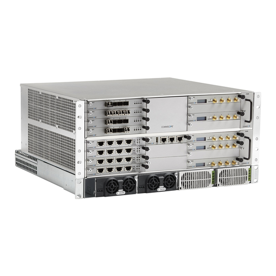
WCS-4 S UBRACKS AND ODULES This section provides information on the WCS-4 and WCS-2 Subracks (Figure 3-1), which dependent on their configuration, become a Central Area Nodes (CAN) or a Transport Expansion Nodes (TEN). The CAN is the server-level control and primary signal distribution within an ION-E system. • The TEN is the secondary distribution point that connects to a CAN using Multi-Mode or Single-Mode • fiber. The WCS-4 is four Rack-Units (RUs) high, and is typically used as a CAN, but can also serve as a TEN. • The WCS-2 is two RUs high, and is typically used as a TEN, but can also serve as a CAN. • WCS-2 Subrack WCS-4 Subrack Figure 3-1. WCS-2 and WCS-4 Subracks ® -E Series Hardware Installation Guide M0201AA Page 14 © June 2017 CommScope, Inc. -
Page 21: Wcs Subrack Front Panel Card Slots And Gui Identification
Remote Power for UAPs and CAP Ls over Cat6A only available in slots L1 - L4. WCS Subracks configured as TENs do not currently support RFD Cards. ® M0201AA -E Series Hardware Installation Guide © June 2017 CommScope, Inc. Page 15... -
Page 22: Wcs Subrack Back Panel Connectors
Ground (earth) connection to the Power Supply Subrack UNRESOLVED: This looks like it is the rear of the WCS-2. Are the connectors laid out the same on WCS-4? ® -E Series Hardware Installation Guide M0201AA Page 16 © June 2017 CommScope, Inc. -
Page 23: Wcs Subrack Alarm Connector
IN 4 Relay NO The Alarm connector on the back panel of the WCS-4 and WCS-2 subracks has four opto-isolated (chassis-ground referenced) dry contact inputs to monitor external devices • one Summary Alarm Relay that energizes when specific alarms are triggered—the thresholds of which • are shown in the preceding graphic. [ Which alarms? We need to match the Summary Alarms shown above with the actual corresponding alarms. ® M0201AA -E Series Hardware Installation Guide © June 2017 CommScope, Inc. Page 17... -
Page 24: Wcs Fan Modules And Filters
WCS-2 and WCS-4 Subracks and Modules WCS Fan Modules and Filters Fan Module Filter The following rules apply to the WCS Fan Modules and Filters: Fan Modules and Filters must be installed for WCS operation, but they can be replaced without system • interruption. Filters are inserted on the left side of the WCS; two filters are required for a WCS-4. • Fan Modules (are inserted on the right side of the WCS chassis; two Fan Modules are required for a WCS-4. • ® -E Series Hardware Installation Guide M0201AA Page 18 © June 2017 CommScope, Inc. -
Page 25: System User Interface Card (Sui)
LAN1 port RJ-45 jack (female) Reserved for future use. LAN2 port RJ-45 jack (female) Connects to a LAN or modem; DHCP or specified fixed IP address ® M0201AA -E Series Hardware Installation Guide © June 2017 CommScope, Inc. Page 19... -
Page 26: Rf Donor Card (Rfd)
Path 1 and Path 2 of an LTE MIMO BTS must be connected to either Ports 1 and 2 of the RFD Card as a pair, or to Ports 3 and 4 as a pair. ® -E Series Hardware Installation Guide M0201AA Page 20 © June 2017 CommScope, Inc. -
Page 27: Optical Transport Card (Opt)
SFP Port LED numbers correspond with the SFP port numbers. When the OPT Card is installed in a TEN, only SFP Port LED 1 is functional. ® M0201AA -E Series Hardware Installation Guide © June 2017 CommScope, Inc. Page 21... -
Page 28: Copper Transport Card (Cat)
• A CAN/TEN with four CAT cards installed can support up to twenty-four UAPs. Unless otherwise noted, the use of “UAP” collectively refers to the UAP, UAP-X, UAP-N25, and the CAP L. ® -E Series Hardware Installation Guide M0201AA Page 22 © June 2017 CommScope, Inc. -
Page 29: Auxiliary Unit Transport Card (Aut)
If the Right LED is green, to know if it means 100 Mbit/s vs. not connected, to be not connected, wouldn’t the Left LED be off? UNRESOLVED: Confirm Gbps can replace Gbit/s and Mbps = Mbit/s ® M0201AA -E Series Hardware Installation Guide © June 2017 CommScope, Inc. Page 23... -
Page 30: Installing Subracks And Psus In An Equipment Rack
WCS Subrack (WCS-2 is 2 RU high and WCS-4 is 4RU high) Disconnect all input to the PSU before adding it to or removing it from an equipment rack. ® -E Series Hardware Installation Guide M0201AA Page 24 © June 2017 CommScope, Inc. -
Page 31: Connect The Subrack And Psu Power And Communication Cables
Subrack ground (required) e-POI communica ons To/From eNodeB e-POI power Subrack ground (required) WCS DC power Rec fier control 85 to 264 Vac Subrack ground (required) ® M0201AA -E Series Hardware Installation Guide © June 2017 CommScope, Inc. Page 25... - Page 32 Rear Panel of PSU +57 Vdc Power terminal +12 Vdc Power terminal - 57 Vdc Power terminal - 12 Vdc Power terminal Rec fier Control connector Connect the Ground stud on the WCS, PSU, and e-POI subracks to a suitable ground (earth) according to local and national electrical codes. ® -E Series Hardware Installation Guide M0201AA Page 26 © June 2017 CommScope, Inc.
-
Page 33: Install The Can And Ten Cards
Tighten the two thumbscrews that secure the card in the subrack chassis. Do not leave any unoccupied slots open; replace blank faceplates, as necessary.. To maximize airflow through the WCS chassis, blank panels must be installed in all empty Card slots. If additional blank faceplates are required, you can order them from CommScope (see "Contacting DCCS Global Technical Support” on page 126). -
Page 34: Install Sfp+ Transceivers In The Opt Cards
Should you need to remove an SFP+ Transceiver, press down on its extraction lever, and then carefully pull the transceiver out of the slot. UNRESOLVED: Connect to what? R1.1 to CAN - otherwise? Cable? ® -E Series Hardware Installation Guide M0201AA Page 28 © June 2017 CommScope, Inc. -
Page 35: Connect The Rfd Cards
SISO Services (CDMA, UMTS, GSM. LTE SISO) LTE MIMO Pair LTE MIMO Pair to/from to/from BTS/eNode or e-POI BTS/eNode or e-POI If the signal levels of the BTS exceed the maximum input level of +27 dBm, an e-POI RF card or other suitable attenuator must be used to attenuate the signal. For optimum PIM performance, the composite level into a Donor (RFD Card) port should be less than 16 dBm. If only one carrier is in a band, PIM is probably not a concern. For the case of two or more carriers in a band, spurious intermods due to PIM could land in the UL causing interference. Whether or not PIM will cause interference depends on the spacing between UL and DL and the frequencies of active carriers. ® M0201AA -E Series Hardware Installation Guide © June 2017 CommScope, Inc. Page 29... -
Page 36: Connect The Cat Cards
CAT Ports 1 - 4 to/from UAP Main port UAP, UAP-N25 UAP-X CAT Ports 1 - 4 to/from CAP L Op cal Port 1 CAP L ® -E Series Hardware Installation Guide M0201AA Page 30 © June 2017 CommScope, Inc. - Page 37 CAT Ports 1 - 3 to/from UAP Main port UAP, UAP-N25 UAP-X CAT Ports 1 - 3 to/from CAP L Op cal Port 2 CAP L ® M0201AA -E Series Hardware Installation Guide © June 2017 CommScope, Inc. Page 31...
-
Page 38: Connect The Aut Cards
The outside network that supports the Ethernet device connected to the UAP must be connected to the • corresponding AUT Card and port of the subrack containing the CAT card to which the UAP is connected. Ethernet backhaul over the optical link is not supported. Because the path from the UAP AUX port to an AUT port path is a pass-through connection, no extra • network setup procedures for the Ethernet device are required. Because the UAP's AUX port is configured to support a second UAP by default, there will be a delay before • the Ethernet backhaul path at the AUT Card is ready to use when the device is initially connected. When an Ethernet device is connected to the AUX port of a UAP, ION-E detects the device, re-flashes the UAP to support the device, and then reboots the UAP. The UAP will perform the re-flash and reboot process whenever the UAP or Ethernet device connected to the AUX port is changed. The UAP's blue LED will blink while re-flashing without interrupting service, but the UAP will experience a short service interruption of approximately 1.5 minutes when it reboots. The AUT path is independent of the signal set assigned to a UAP, however, the maximum transport • bandwidth for the UAP is reduced from 320 MHz to 280 MHz when an Ethernet device is connected to the UAP. The AUX port of a cascaded (secondary) UAP cannot be used to connect an Ethernet device. • The AUT Card ports do not supply power, however, the UAP does supply Remote Power over Cat6A to • connected Ethernet devices. 1 Gbit/s and 100 Mbit/s Ethernet devices are supported. • ® -E Series Hardware Installation Guide M0201AA Page 32 © June 2017 CommScope, Inc. - Page 39 WCS Slot CAT Port AUT Slot AUT Port Figure 3-3. Example of Internal Mapping of CAT Card Ports to AUT Ports Use the preceding information and the following steps to connect the AUT Card(s) to the ION-E system. Follow the steps in "Install the CAN and TEN Cards” on page 27 to install the AUT Card(s) into the WCS Subrack Slots M1 - M2, as needed for this CAT/TEN installation. Refer to Figure 3-3 and Table 3-1 to connect Ethernet cables from the Ethernet devices to the AUT Card's RJ45 ports. ® M0201AA -E Series Hardware Installation Guide © June 2017 CommScope, Inc. Page 33...
- Page 40 Installing Subracks and PSUs in an Equipment Rack ® -E Series Hardware Installation Guide M0201AA Page 34 © June 2017 CommScope, Inc.
-
Page 41: Point Of Interface (E-Poi) Subracks
Schiele, who is out of the office until 3July17. UNRESOLVED: Also, not sure why the e-POI was not included in the ION-E Series Software Version 2.0.0 User’s Manual (PN M0201A0D), but I am adding it to this new ION-E HW install guide. -
Page 42: Point Of Interface (E-Poi) Subrack
Subrack supports up to 8 RFD Cards (IFC) e-POI Subrack Back Panel Connectors Ground studs Communica on ports (to WCS Subrack) 12 Vdc Input connector (from WCS Subrack) 15A Blade Fuse ® -E Series Hardware Installation Guide M0201AA Page 36 © June 2017 CommScope, Inc. -
Page 43: Interface Card (Ifc)
For e-POI Module Status LEDS” Red state, original doc said was “IFC temperature alarm,” which does not make sense, as there are 8 LEDs. However, please verify that my correction above is correct. ® M0201AA -E Series Hardware Installation Guide © June 2017 CommScope, Inc. Page 37... -
Page 44: E-Poi Module
Subrack Power/Com port UL/DL Ports 7/16 DIN connectors Connect to the eNodeB. The Ribbon cable is connected after the e-POI Module is installed in the e-POI Subrack. ® -E Series Hardware Installation Guide M0201AA Page 38 © June 2017 CommScope, Inc. -
Page 45: Installing An E-Poi Subracks And Modules
Installing an e-POI Subracks and Modules -POI S NSTALLING AN E UBRACKS AND ODULES UNRESOLVED: I could not find any installation steps. Emulate what was provided for WCS subracks? ® M0201AA -E Series Hardware Installation Guide © June 2017 CommScope, Inc. Page 39... -
Page 46: Removing An E-Poi Module From An E-Poi Subrack
Removing an e-POI Module from an e-POI Subrack -POI M -POI S EMOVING AN E ODULE FROM AN E UBRACK The ION-E Software automatically detects when an e-POI Module is added to an e-POI Subrack. If you need to remove an e-POI Module, you must do the following: Disconnect the Ribbon cable from the e-POI Module that you are removing from the e-POI Subrack. Loosen the two thumbscrews on the bottom of the e-POI Module and pull it from the subrack. Press the Config button on the IFC for 5 seconds. This tells the ION-E Software to scan and delete the removed e-POI Module from inventory and clear any alarms related to that e-POI Module. Wait for the e-POI Module Status LEDS on the IFC to flash off and then on, which indicates that the IFC has been reconfigured. e-Poi Module ® -E Series Hardware Installation Guide M0201AA Page 40 © June 2017 CommScope, Inc. -
Page 47: E-Poi Subrack And Component Specifications
• 33.5 ±3.2 450-698 MHz RF input power +46 dBm PIM @ 2x20 Watts (3rd order) -153 dBc Input voltage, Vdc / Power consumption 12/10 Watts ® M0201AA -E Series Hardware Installation Guide © June 2017 CommScope, Inc. Page 41... - Page 48 Subrack and Component Specifications ® -E Series Hardware Installation Guide M0201AA Page 42 © June 2017 CommScope, Inc.
-
Page 49: Power Supply Unit (Psu)
Power Supply Unit (PSU) ..................................... 44 PSU Modules and Connectors ..................................44 12 Vdc Power Module LEDs.................................... 45 57 Vdc Power Module LEDs.................................... 46 Installing PSUs ........................................47 This chapter provides a product overview and installation instructions for the ION-E Series Power Supply Unit (PSU). ® M0201AA -E Series Hardware Installation Guide © June 2017 CommScope, Inc. Page 43... -
Page 50: Power Supply Unit (Psu)
Provides the connection point for the RTN Negative (Black Wire). Unless otherwise noted, the use of “UAP” collectively refers to the UAP, UAP-X, UAP-N25, and the CAP L. ® -E Series Hardware Installation Guide M0201AA Page 44 © June 2017 CommScope, Inc. -
Page 51: 12 Vdc Power Module Leds
(cable unplugged) from one of the modules. • If only one 12 Vdc Power Module is installed in the PSU, and AC power is removed. ® M0201AA -E Series Hardware Installation Guide © June 2017 CommScope, Inc. Page 45... -
Page 52: Vdc Power Module Leds
AC present but not within limits Blinks AC not present Over current Blinks Non-catastrophic internal failure (any detectable fault that does not shut down the unit) Communications fault (RS485 mode) Blinks ® -E Series Hardware Installation Guide M0201AA Page 46 © June 2017 CommScope, Inc. -
Page 53: Installing Psus
Installing PSUs NSTALLING UNRESOLVED: I could not find any installation steps. UNRESOLVED: Do we have any power consumption specs? ® M0201AA -E Series Hardware Installation Guide © June 2017 CommScope, Inc. Page 47... - Page 54 Installing PSUs ® -E Series Hardware Installation Guide M0201AA Page 48 © June 2017 CommScope, Inc.
-
Page 55: Universal Access Points
UAP product name. For information on the Carrier Access Point, Low Power (CAP L), go to "Carrier Access Point, Low Power (CAP L)” on page ® M0201AA -E Series Hardware Installation Guide © June 2017 CommScope, Inc. Page 49... -
Page 56: Identifying Uaps In The Ion-E Software
UAP.L8.1a UAP.L8.1b UAP.L4.2a UAP.L4.2b UAP.L8.2a UAP.L8.2b UAP.L4.3a UAP.L4.3b UAP.L8.3a UAP.L8.3b UAP.L4.4a UAP.L4.4b UAP.L8.4a UAP.L8.4b UAPs with external antenna connectors are identified as UAP-X on the Signal Distribution page as shown in Figure 6-1. Figure 6-1. Identifying UAP-X Units in the ION-E Software ® -E Series Hardware Installation Guide M0201AA Page 50 © June 2017 CommScope, Inc. -
Page 57: Uaps And Uap-N25S
• Unit Identifier activated in the ION-E GUI; for information on how to flash identify a UAP, see “Flash UAP Led” section of the ION-E Series software configuration guide that corresponds to the ION-E Software Release installed on this ION-E system. -
Page 58: Uap-X
• Unit Identifier activated in the ION-E GUI; for information on how to flash identify a UAP, see “Flash UAP Led” section of the ION-E Series software configuration guide that corresponds to the ION-E Software Release installed on the this ION-E system. -
Page 59: Installing Uaps
Unpack each container while carefully checking the contents for damage and verify with the packing slip. Table 6-2. Components of the UAP Wall Mounting Kit (PN 7683182-00) Quantity Component Description Template UAP Shroud Two-Part Sliding Support Bars If damage is found or parts are missing, file a claim with the commercial carrier and notify CommScope Technical Support (see "Contacting DCCS Global Technical Support” on page 126). Save the damaged cartons for inspection by the carrier. Save all shipping containers for use if the equipment requires shipment at a future date. ® M0201AA -E Series Hardware Installation Guide © June 2017 CommScope, Inc. Page 53... -
Page 60: Standard Ceiling Mount Overview
6 meters from the UAP-X or more than 2 meters from the units if steps are taken to mitigate interference from the Cat6A cables. Please see the UAP-X Antenna Installation Guidelines document for more details. ® -E Series Hardware Installation Guide M0201AA Page 54 © June 2017 CommScope, Inc. -
Page 61: Standard Ceiling Mount Installation Steps
Standard Ceiling Mount Installation Steps Using the supplied template as a guide, cut an opening in the center of a ceiling tile for the UAP. Place the UAP on a flat surface such as a table with the top of the unit face down (connectors up). Place the shroud over the top of the UAP so that the screw holes and cable cutouts align properly. Place the ceiling tile over the shroud with the finished surface of the ceiling tile facing downward. Place the two-part sliding support bar on top of the shroud and align it with the center of the UAP. Place mounting bracket over the sliding support bar and align it with the threaded mounting holes in the UAP. Sliding Moun ng Bracket Ceiling le Recommended overhead clearance UAP Shroud is 70 cm (27.6 in) Ceiling grid ® M0201AA -E Series Hardware Installation Guide © June 2017 CommScope, Inc. Page 55... - Page 62 Always lift the UAP by the support bar or the face of the unit. Do not lift the UAP by holding the edge of the ceiling tile. 11 Connect the Cat6A cables to the Main and AUX ports of the UAP. 4 M5 x 10 screws Thumbscrews Locking nuts Support-Bar clips ® -E Series Hardware Installation Guide M0201AA Page 56 © June 2017 CommScope, Inc.
-
Page 63: Mounting A Uap Using A Uap Quick Release Ceiling Mount Kit
UAP Ceiling Mount Assembly (PN 7683182-00)” on page The UAP quick release ceiling mount kit is designed to be installed in a standard 60 cm x 60 cm (2'x2') suspended ceiling grid. If the grid uses 120 cm x 60 cm (4'x2') ceiling tiles, add an additional cross-runner (cross-tee) to the main runner to support the unit. A minimum overhead clearance of 70 cm is recommended. UAP wall mounting kit 7683181-00 is also available from CommScope for mounting a UAP to a wall or hard ceiling. Required Tools for a Quick Release Ceiling Mount Kit 8 mm metric torque wrench to secure the Guide-Lock pins and thumbscrew lock nuts • Cutting tool to cut open ceiling tile • ® M0201AA -E Series Hardware Installation Guide © June 2017 CommScope, Inc. Page 57... -
Page 64: Unpack And Inspect The Quick Release Ceiling Mount Kit
Recommended overhead clearance is 70 cm (27.6 in) Ceiling grid It is the responsibility of the installer to ensure that the UAP is safely installed. ® -E Series Hardware Installation Guide M0201AA Page 58 © June 2017 CommScope, Inc.
Need help?
Do you have a question about the ION-E Series and is the answer not in the manual?
Questions and answers