Table of Contents
Advertisement
Quick Links
Installation
and
Maintenance
Manual
with
Safety Information
and Parts List
RECOMMENDED SPARE PARTS HIGHLIGHTED IN GRAY
CAN BE SHIPPED FROM JONESBORO, AR THE SAME DAY.
Effective June, 1997
Model TH
Bulletin #1027
Jonesboro, Arkansas
HYTROL CONVEYOR CO., INC.
St. Louis, Missouri
Manteca, California
© COPYRIGHT 1997–HYTROL CONVEYOR CO., INC.
Advertisement
Table of Contents

Related Manuals for HYTROL TH


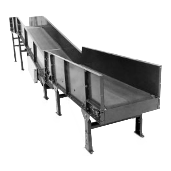
Summary of Contents for HYTROL TH
- Page 1 Parts List RECOMMENDED SPARE PARTS HIGHLIGHTED IN GRAY CAN BE SHIPPED FROM JONESBORO, AR THE SAME DAY. Effective June, 1997 Model TH Bulletin #1027 Jonesboro, Arkansas HYTROL CONVEYOR CO., INC. St. Louis, Missouri Manteca, California © COPYRIGHT 1997–HYTROL CONVEYOR CO., INC.
-
Page 2: Table Of Contents
Operation Safety Precautions ..7 Model TH Parts List ....17 Conveyor Start-Up ....7 8”... -
Page 3: Receiving And Uncrating
INTRODUCTION This manual provides guidelines and procedures for installing, the manual. For safety to personnel and for proper operation operating, and maintaining your conveyor. A complete parts of your conveyor, it is recommended that you read and follow list is provided with recommended spare parts highlighted in the instructions provided in this manual. -
Page 4: Support Installation
ADJUST TO DESIRED ITEM ITEM ELEVATION HYTROL CONVEYOR CO. INC. HYTROL CONVEYOR CO. INC. JONESBORO, AR • ST. LOUIS, MO • MANTECA, CA JONESBORO, AR • ST. LOUIS, MO • MANTECA, CA Ceiling Hanger Installation If conveyors are to be used in an overhead application, ceiling FIGURE 4B hangers may have been supplied in place of floor supports. -
Page 5: Conveyor Set-Up
Conveyor Set-Up 1. . . Mark a chalk line on floor to locate center of the con- FIGURE 5A veyor. 2. . . Place the drive section in position. 3. . . Install remaining sections, placing end without support on extended support of previous section (Figures 4A and 5A). -
Page 6: Electrical Equipment
Electrical Equipment or are beyond voice and visual contact from drive areas, WARNING! loading areas, transfer points, and other potentially haz- Electrical controls shall be installed and ardous locations on the conveyor path not guarded by wired by a qualified electrician. Wiring location, position, or guards, shall be furnished with information for the motor and controls are emergency stop buttons, pull cords, limit switches, or... -
Page 7: Operation
OPERATION Operation Safety Precautions A) Only trained employees shall be permitted to operate conveyors. Training shall include instruction in operation E) Personnel working on or near a conveyor shall be under normal conditions and emergency situations. instructed as to the location and operation of pertinent stop- ping devices. -
Page 8: Belt Installation
Belt Installation INSTALLING THE BELT FIGURE 8B The conveyor belt has been cut to the proper length and lac- BELT LACING ing installed at the factory. To install follow these steps: 1. . . Thread belt through conveyor as shown in Figure 8A. 2. -
Page 9: Belt Tracking
Belt Tracking HOW IS THE CONVEYOR BELT TRACKED SQUARING PULLEYS IN FIGURE 9A CENTER DRIVE The belt is tracked by adjusting: Drive Pulley, Tail Pulley, “A” TAKE-UP Return Idlers, and Snub Idlers. The same tracking principles apply to conveyors supplied with end drives, center drives, or underside take-ups. - Page 10 Belt Tracking (Continued) HOW TO STEER THE BELT CAUTION! Condition 1. . .When the belt is running in the direction Only trained personnel should track convey- (FLOW) with the arrow, but tracking (drifting) towards Side “X”, or belt which must be done while conveyor move the Snub Idler nearest the INFEED end of Side “Y”...
-
Page 11: Maintenance
Lubrication BEARINGS REDUCERS STANDARD: Supplied sealed and pre-lubricated. No MANUFACTURED BY HYTROL: See separate manual lubrication required. in Packing Envelope that contains lubrication and main- tenance instructions for HYTROL’s Gear Reducer. CHAIN It is recommended that the drive chain be lubricated with MANUFACTURED BY OTHERS: Refer to their recom- SAE-30 oil approximately every 40 hours of operation. -
Page 12: Drive Chain Alignment And Tension
Drive Chain Alignment and Tension The drive chain and sprockets should be checked peri- FIGURE 12A odically for proper tension and alignment. Improper adjustment will cause extensive wear to the drive com- ponents. TO MAKE ADJUSTMENTS 1. . . Remove chain guard. REDUCER 2. -
Page 13: Trouble Shooting
2) Low voltage to motor. 2) Have electrician check and correct as necessary. 3) Low lubricant level in reducer. 3) Relubricate per manufacturer’s recommendations. For HYTROL reducer, refer to separate manual. 1) Conveyor is overloaded. 1) Reduce load. Belt doesn’t move, but drive runs. -
Page 14: Preventive Maintenance Checklist
HYTROL Distributor. 2. . . Give Conveyor Model Number and Serial Number or JONESBORO, ARKANSAS ST. LOUIS, MISSOURI MANTECA, CALIFORNIA HYTROL Factory Order Number. SERIAL # 775544 3. . . Give Part Number and complete description from Parts List. -
Page 15: Notes
Notes... -
Page 16: Model Th Parts Drawing
Model TH Parts Drawing 6’ DIA. TAIL PUL- 31” - 49” BR UP TO 150’ 28 29 30 “A” “A” 20 21 4’ DIA. TAIL PUL- SECTION “A-A” 9 10... -
Page 17: Model Th Parts List
Model TH Parts List See Page 14 For Information On How to Order Replacement Parts Recommended Spare Parts List Highlighted in Gray Ref. No. Part No. Description Ref. No. Part No. Description — Drive Assembly (See Page 18) — B - 0 5 0 4 0 4 in. -
Page 18: 8" Center Drive Parts Drawing & List
8” Center Drive Parts Drawing & Parts List See Page 14 For Information On How to Order Replacement Parts Recommended Spare Parts List Highlighted in Gray 1-1/2" 1-1/2" Ref. No. Part No. Description Ref. No. Part No. Description — Motor—C-Face B - 0 5 9 4 6 Motor Base Support Angle Assembly —... -
Page 19: Drawing & List
Underside Take-Up Parts Drawing & List 10 11 See Page 14 For Information On How to Order Replacement Parts 1-1/2" 1-1/2" Recommended Spare Parts List Highlighted in Gray Ref. No. Part No. Description Ref. No. Part No. Description — Side Channel Assembly - RH B - 0 4 6 5 5 Lower Bearing Guide Spacer —... - Page 20 HYTROL CONVEYOR COMPANY, INC. 2020 Hytrol Drive Jonesboro, Arkansas 72401 Phone: (870) 935-3700 EFFECTIVE JUNE, 1997 Printed 6/97 Creative Multigraphics, Inc.
Need help?
Do you have a question about the TH and is the answer not in the manual?
Questions and answers