Table of Contents
Advertisement
Quick Links
IMPORTANT!
DO NOT DESTROY
I n s t a l l a t i o n
a n d
M a i n t e n a n c e
M a n u a l
with
Safety Information
and Parts List
RECOMMENDED SPARE PARTS HIGHLIGHTED IN GRAY
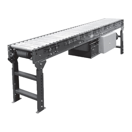
Model 190-LR &
Model 190-ACZ
HYTROL CONVEYOR CO., INC.
© COPYRIGHT 2005–HYTROL CONVEYOR CO., INC.
IMPORTANTE!
NO DESTRUIR
de Instalación
M a n t e n i m i e n t o
con
LAS PARTES DE REPUESTO RECOMENDADAS SE RESALTAN EN GRIS
190-ACZ
M a n u a l
y
Información sobre Seguridad
y Lista de Partes
Effective June 2005
(Supercedes November 2003)
Bulletin # 558
Jonesboro, Arkansas
190-LR
Advertisement
Table of Contents


Need help?
Do you have a question about the 190-ACZ and is the answer not in the manual?
Questions and answers