Table of Contents
Advertisement
IMPORTANT!
DO NOT DESTROY
Installation
and
Manual
with Safety Information
and Parts List
RECOMMENDED SPARE PARTS HIGHLIGHTED IN GRAY
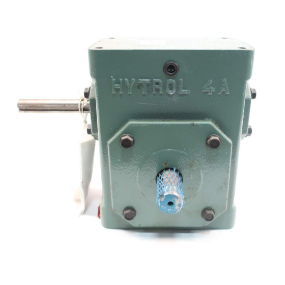
Speed Reducers 4A, 4AC, 5A, 5AC
(Reductores de Velocidad 4A, 4AC, 5A, 5AC)
PRESS OPTIMIZED FOR THE ENVIRONMENT
(IMPRESIÓN OPTIMIZADA PARA PROTEGER EL MEDIO AMBIENTE)
¡IMPORTANTE!
NO DESTRUIR
HYTROL | Jonesboro, Arkansas
© COPYRIGHT 2009–HYTROL CONVEYOR CO., INC.
Manual
de Instalación
Mantenimiento
con Información sobre Seguridad
y Lista de Refacciones
LAS REFACCIONES RECOMENDADAS SE RESALTAN EN GRIS
Effective April 2017
(Supercedes May 2014)
Bulletin #684
y
Advertisement
Table of Contents


Need help?
Do you have a question about the 4A and is the answer not in the manual?
Questions and answers