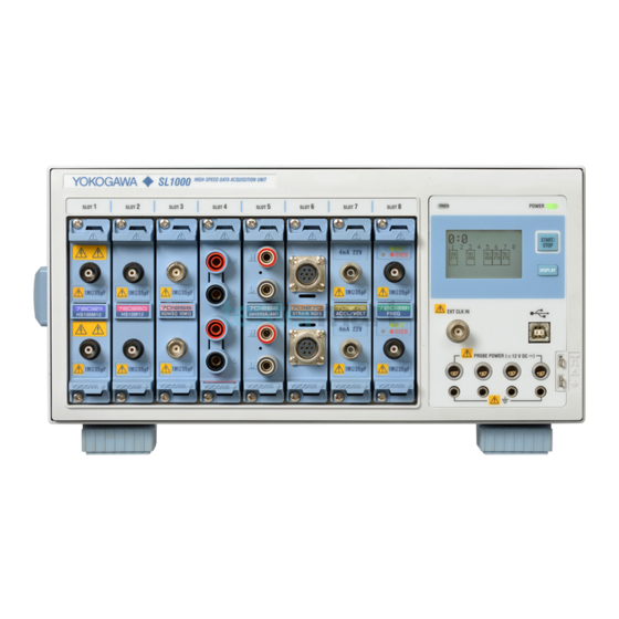
YOKOGAWA SL1000 User Manual
High-speed data acquisition unit
Hide thumbs
Also See for SL1000:
- User manual (107 pages) ,
- User manual (96 pages) ,
- User manual (51 pages)
Table of Contents
Advertisement
Quick Links
Advertisement
Table of Contents

Related Manuals for YOKOGAWA SL1000


Summary of Contents for YOKOGAWA SL1000
- Page 1 SL1000 Acquisition Software IM 720120-61E 10th Edition...
-
Page 2: List Of Manuals
After reading the manual, keep it in a convenient location for quick reference whenever a question arises during operation. List of Manuals The following manuals, including this one, are provided as manuals for the SL1000. Please read all of them. Manual Title Manual No. - Page 3 Trademarks • Microsoft, Internet Explorer, Windows, Windows 7, Windows 8, and Windows 10 are either registered trademarks or trademarks of Microsoft Corporation in the United States and/or other countries. • Adobe, Acrobat, and PostScript are trademarks of Adobe Systems Incorporated. •...
-
Page 4: Terms And Conditions Of The Software License
5.2 In the case of the preceding Paragraph 5.1, the Licensee shall assign to Yokogawa all of the rights to defend the Licensee and to negotiate with the claiming party. Furthermore, the Licensee shall provide Yokogawa with necessary information or any other assistance for Yokogawa’s defense and negotiation. If and when such a claim should be attributable to Yokogawa, subject to the written notice to Yokogawa stated in the preceding Paragraph 5.1, Yokogawa shall defend the Licensee and... - Page 5 Article 6 (Liabilities) 6.1 If and when the Licensee should incur any damage relating to or arising out of the Licensed Software or service that Yokogawa has provided to the Licensee under the conditions herein due to a reason attributable to Yokogawa, Yokogawa shall take actions in accordance with this Agreement. However, in no event shall Yokogawa...
-
Page 6: How To Use This Manual
Explains how to display waveforms of data measured in the past, how to save the SL1000’s measured data to your PC, how to save setup data, how to load previous setup data, how to save computed data and screen captures of measured waveforms, how to average and save measured data, and how to transfer files between the SL1000 and your PC. -
Page 7: Table Of Contents
Installing or Uninstalling the Acquisition Software ............2-2 Installing the USB Driver ....................2-4 Starting and Exiting the Acquisition Software ..............2-7 Chapter 3 Connecting to the SL1000 Connecting Using the USB ....................3-1 Specifying Communication Settings (When Using the Optional Ethernet Interface) ..3-2 3.3. - Page 8 Chapter 8 Saving, Loading, and Transferring Data Saving and Loading Measured Data ................8-1 Saving and Loading Setup Data ..................8-3 Saving the SL1000’s Data to Your PC ................8-4 Averaging and Saving History Data.................. 8-6 Saving Computed Data ....................8-8 Saving Waveform Screen Captures .................
- Page 9 Converting Waveform Data Files to CSV or Binary Files ..........10-19 Chapter 11 Maintenance 11.1 Troubleshooting .......................11-1 11.2 Messages ........................11-2 Chapter 12 Specifications 12.1 Connection to the SL1000 ....................12-1 12.2 Measurement Functions ....................12-1 12.3 Trigger Function ......................12-2 12.4 Recording Function ......................12-3 12.5 Functions ........................
-
Page 10: Chapter 1 What The Acquisition Software Can Do
1.5. Measured Raw Data All the measured data that the SL1000 acquired. The data is sent to your PC in unit of measuring groups to save the data on the hard disk of your PC. For a description of measuring groups, see section 1.2. - Page 11 After the measurement stops, all the measured data acquired in the internal memory of an SL1000 can be saved as a single file on your PC. This task is referred to as saving not recording in which data is saved while the measurement is in progress.
- Page 12 720901-02 (3 m in length). For instructions on how to connect the SL1000s to your PC for synchronous operation and for details on the sync I/O connectors (SYNC IN and SYNC OUT), see the SL1000 High-Speed Data Acquisition Unit User’s Manual (IM 720120-01E).
- Page 13 To perform synchronous operation, set the master and slave units to the same group ID (from 0 to F). Set the master unit’s unit ID to 0, and slave units’ unit IDs in ascending order from 1 to 7. For details, see section 4.1 in the SL1000 High-Speed Data Acquisition Unit User’s Manual (IM 720120-01E).
- Page 14 Set the measurement conditions Set the record conditions Set the display conditions Start measurement Start measurement Start recording Start recording * For details on each setup item, see the operation flow diagram “Connecting to the SL1000 for the First Time.” Index IM 720120-61E...
-
Page 15: Connection & Group Settings
1.1 Overview of This Software Setup in Wizard Format The basic setup consisting of connection and group settings, measurement settings, recording settings, and display settings can be specified easily using dialog boxes in wizard format. You can also specify the connection and group settings, measurement settings, recording settings, and display settings individually using the toolbar or menu bar. - Page 16 Search for an SL1000 that is to communicate with your PC. If connected using the USB, you can search for an SL1000 by specifying a group ID. If connected using the Ethernet interface, you can search by specifying a group ID and IP address.
- Page 17 1.2 Connection & Group Settings Measuring Groups Modules installed in a connected SL1000 are registered to measuring groups according to the sample rate used to make measurements. Up to four measuring groups can be set Measurement is performed only on modules that are registered to measuring groups.
- Page 18 Data is acquired immediately upon starting a measurement. The SL1000 continues to acquire data until the measurement is stopped. The measured data can also be recorded to the hard disk of the SL1000 or your PC at a specified time or when an alarm occurs.
- Page 19 Internal Clock The sampling timing of the measured data is controlled using the clock signal (internal clock) that is generated from the internal time-base circuit of the SL1000. External Clock The sampling timing of the measured data is controlled using a clock signal applied externally.
-
Page 20: Measurement Settings
For example, if the sample rate of measuring group 1 is set to 500 kS/s, the sample rate of other measuring groups cannot be set to 200 kS/s (the next lower sample rate). The SL1000 can display waveforms correctly for frequencies less than one-half the sample rate as defined by the Nyquist sampling theorem.* * If the sample rate is comparatively low with respect to the input signal frequency, the harmonics contained in the signal are lost. - Page 21 1.3 Measurement Settings Input Coupling If you want to measure only the amplitude of an AC signal, measurement is easier if the DC component is removed from the input signal. On the other hand, there are times when you want to check the ground level or measure the entire input signal (both the DC and AC components).
- Page 22 • Applies the signal with no distortion. • Expands the measurable voltage (current) range of the SL1000. When using a probe, the attenuation setting on the SL1000 must be set equal to the probe attenuation or current-to-voltage conversion ratio so that the measured voltage (current) can be read directly.
- Page 23 1.3 Measurement Settings Linear Scaling The measured data can be scaled to any physical value and displayed. When measuring the voltage (current), strain, or frequency (number of rotations, period, duty cycle, power supply frequency, pulse width, pulse integration, and velocity), there are two methods of linear scaling: “aX+b”...
- Page 24 1.3 Measurement Settings RMS Measurement If the module is 701267 (HV (with RMS)) or 720268 (HV (with RMS/AAF)), you can observer the RMS value of the input signal. AC-RMS This setting is used when you want to observe only the rms values of the AC signal, eliminating the DC components from the input signal.
- Page 25 You can turn ON/OFF the internal RJC circuit of the SL1000. Use this setting to enable the reference junction compensation by the internal RJC circuit.
- Page 26 You can set the bridge voltage (excitation: voltage applied to the bridge) from 2 V, 5 V, and 10 V on the SL1000. However, since the mV/V value is a converted value, the measured value is basically constant.
- Page 27 (A charge output type acceleration sensor that does not have a built-in amplifier cannot be connected directly to the 701275 (ACCL/ VOLT). For details on how to connect acceleration sensors, see the SL1000 High-Speed Data Acquisition Unit User’s Manual (IM 720120-01E).) Note The 701275 (ACCL/VOLT) can also measure voltage.
- Page 28 1.3 Measurement Settings Frequency Measurement The Frequency Module (701281 (FREQ) or 720281 (FREQ)) measures frequency, number of rotations, period, duty cycle, power supply frequency, pulse width, pulse integration, and velocity. Measured Item Frequency Frequency F (Hz) = 1/Tw (s) Measurable range: 0.01 Hz to 500 kHz Tw(s) RPMs/RPSs...
- Page 29 1.3 Measurement Settings Pulse Integration (Distance/Flow Rate) Pulse integrated value = N (count) × physical amount per pulse (I) Set the physical amount per pulse (I) to distance or flow rate. A suitable user-defined unit can be assigned to the specified physical amount. Measurable range: up to 2×10 counts N (count) Velocity Velocity (km/h) = Distance per pulse l (km)/Tw (s) × 3600 Velocity (m/s) = Distance per pulse l (m)/Tw (s) The distance and unit can be defined by the user (angular velocity, etc.).
- Page 30 1.3 Measurement Settings Filter Smoothing filter (moving average) The frequency module can display waveforms by taking the moving average of the data in realtime. The order of moving average can be set in terms of time in the range of 0.0 ms to 1 s (up to 25000th order).
-
Page 31: Recording Settings
All the measured data in the memory is saved as a single file. The data saved to the hard disk of the SL1000 can be copied to the hard disk of your PC using the accompanying Xviewer (except the /XV0 option) or the FTP function (/C10 option). - Page 32 The SL1000 can also start measuring or recording after a given time elapses from when the trigger condition is met. * The SL1000 will be ready to record if you click the Start Recording button or choose Start Recording from the Acquisition menu.
- Page 33 1.4 Recording Settings Relationship between Measurement and Recording (Auto Recording) Free Run Mode The recording of the measured data is enabled when measurement is in progress. Examples of the measurement state, recording start and stop conditions, and repeat conditions are given below. If Recording Start Condition Is Immediate and Recording Stop Condition Is Continuous ACQ Stop...
- Page 34 Measurement and recording are performed for a specified time if a trigger occurs when the SL1000 is ready to measure and record. If a trigger occurs when the SL1000 is not ready to record, only measurement is performed. ACQ Stop...
- Page 35 File Order There are two methods for recording measured data to the hard disk of your PC or the SL1000: sequential and cyclic. Sequential Records the files sequentially to the hard disk. This method is useful if you want to retain the old data.
- Page 36 The current measured value is displayed using a bar graph, digital display (numeric), analog meter, or thermometer. Current values are measured data that this software retrieves from the SL1000 at 100- ms intervals (Free Run mode) or 1-s intervals (Triggered mode).
-
Page 37: Triggering
After acquiring the measured data as a result of trigger occurrence, the SL1000 does not accept the next trigger until the internal processing of the data is completed. - Page 38 Line Generates a trigger on the rising edge of the power signal that is being supplied to the SL1000. Waveforms synchronized to the commercial power supply frequency (50 Hz or 60 Hz) can be observed. Time Generates a trigger at specified time intervals (1 min to 24 hours) from a specified time.
- Page 39 1.6 Triggering Trigger Pattern, Trigger Level, and Hysteresis Trigger Pattern Select Rise (rising edge), Fall (falling edge), Both (both rising and falling edges), H (high), L (low), IN, OUT, IN (L), or OUT (L). Rise (Rising Edge), Fall (Falling Edge), and Both (Both Rising and Falling Edges) A trigger is generated when the trigger source level becomes greater than or equal to the trigger level;...
- Page 40 Setting a trigger delay allows displaying of waveforms that are acquired a specified time (delay) after the trigger is generated. The function is invalid if the trigger source is set to Time or if the SL1000 is measuring using an external clock. The selectable range of trigger delay is 0 to 10 s.
- Page 41 1.6 Triggering Recording of Measured Data in Triggered Mode If measuring in Triggered Mode, the recording start and stop conditions of measured data as explained in section 1.4 are invalid. Measured data is recorded to the specified hard disk each time a trigger occurs after recording is started. When the measurement caused by a specified trigger stops, recording also stops.
-
Page 42: Analysis Function
Analysis Function Cursor Measurement There are two types of cursors: horizontal cursors and vertical cursors. Two cursors are displayed for each type of cursor. The measured values at the two cursor positions and the difference between the cursors can be displayed. You can move the cursor directly by dragging it or by using the left and right arrow keys on the keyboard. - Page 43 1.7 Analysis Function Time Axis Parameters Rise: Rise time [s] Avg Period: Average period within the measuring range [s] (Average period) Fall: Fall time [s] +Width: Time width above the mesial value [s] Freq: Frequency [Hz] 1/Period (Plus width) Period: Period [s] –Width: Time width below the mesial value [s]...
-
Page 44: Alarms
Low, Middle, and High. System Alarm When a system error occurs, the SL1000 transmits an alarm signal from the rear-panel alarm terminal. You can set an alarm that combines multiple system alarms. The following errors are detected. - Page 45 1.8 Alarms Alarm Output The terminal on the SL1000 rear panel can be used to transmit a TTL logic signal when an alarm occurs. The SL1000 cannot transmit both the channel alarm and system alarm simultaneously. In the case of a channel alarm, the SL1000 can be configured so that the signal level...
- Page 46 You cannot configure GO/NO-GO judgment during synchronous operation. Criteria Specify upper and lower limits for each parameter. The SL1000 judges whether the waveform parameter is within or outside the specified range. You can also specify multiple waveform parameters (up to 16) and perform judgment when all conditions are met (AND) or when any condition is met (OR).
-
Page 47: X-Y Display
If the number of measured data points is greater than the specified number of data points to draw, the SL1000 draws the waveform by reducing the number of data points to the specified number. This reduction is done by taking the midpoint of the maximum and minimum values of multiple measured data points. - Page 48 Recording buffer Status bar Information about the hard disk of your PC or the internal hard disk of the SL1000 Information about the Hard Disk of Your PC or the Internal Hard Disk of the SL1000 Displays information about the hard disk of your PC or the internal hard disk of the SL1000.
- Page 49 1.10 Screen Description I/O State Over-Range Turns red when an over-range occurs. Double-click to display an over-range list screen showing a list of channels that over- range is occurring on. Trigger Signal State The lamp is yellow if the trigger condition is met or if an external trigger signal is being applied.
- Page 50 1.11 Screen Description Adjusting the Background Brightness of the Waveform Display Area (Highlighted Display) Slide the knob to change the background of the waveform display from black to white in steps Turn ON/OFF the Waveform Display Click this area to turn ON/OFF the channel display. Channels that are displayed are indicated in light blue.
- Page 51 Environment Menu A menu used to enter environment settings and communication settings, perform a self- test, display the system information of the SL1000, enable the key lock on the SL1000, initialize the SL1000, and calibrate the SL1000. Utility Menu A menu used to start the included Xviewer software (excluding models with the /XV0 option) and to start the File Utility.
- Page 52 You can also open a setup file saved in the past to change the software settings. Transferring Files You can transfer files between the SL1000 and a PC. You can collectively transfer data that has been recorded in synchronous operation mode or transfer data one unit at a time.
-
Page 53: Basic Operation
1.13 Basic Operation This section explains the basic operation of this software. Text Box You can directly type a value or text. Click the box to show the text cursor or highlight an existing value and type from your keyboard. Text cursor Option Button You can select one of the option buttons. - Page 54 1.13 Basic Operation Collectively Selecting or Clearing the Check Boxes of the Selected Items On a setup screen displayed in table format, you can collectively select or clear the check boxes in a selected range. Select multiple lines containing the check boxes you want to manipulate as described earlier.
- Page 55 At least 500 MB of free space (at least 40 GB recommended when using the auto recording function) Communication Interface USB2.0 Ethernet 1000BASE-T (if the /C10 option is installed in the SL1000) CD-ROM Drive A CD-ROM drive is required to install this software program. CRT and Mouse...
-
Page 56: Installing Or Uninstalling The Acquisition Software
Click Next according to the instructions on the screen. A screen for setting the installation destination is displayed. The default setting is C:\Program Files\Yokogawa\SL1000. To change the destination, click Change and select the desired directory. Check the installation destination and click Next. - Page 57 You are finished with the installation if you are using a model with the /XV0 option, which does not contain Xviewer. Yokogawa > SL1000 is added to the Start > Programs menu of Windows, and a shortcut icon is created on the desktop.
-
Page 58: Installing The Usb Driver
The installation wizard for the USB driver starts (only when the SL1000 is connected to the PC for the first time). Note • To connect a different SL1000 to the PC, you must install a new USB driver. • Refer to the following manual in the installation CD. \YKMUSB\IMB9852UT-01E_050.pdf •... - Page 59 2.3 Installing the USB Driver Select “Don’t search. I will choose the driver to install” for the installation options and click Next. A screen for selecting the device driver to be installed is displayed. Click Have Disk. Click Browse. A screen for specifying the device driver to be installed is displayed. In the usbdriver folder in the installation folder of the Acquisition Software, select the ykmusb.inf file and click OK.
- Page 60 2.3 Installing the USB Driver Check that the path you specified in step 7 is displayed under Copy manufacture’s files from, and click OK. Click Next. The installation starts. When the installation is complete, the wizard completion screen is displayed. Click Finish.
-
Page 61: Starting And Exiting The Acquisition Software
• The communication connector is disconnected. • If the connection method is Ethernet, the specified TCP/IP address and the TCP/IP address of the SL1000 are different. • The group ID of the SL1000 has been changed. Connected unit is remotely The SL1000 is being controlled from another PC. - Page 62 Current Firm Version is not The SL1000 unit firmware version is not supported by this supported, you will not be able to software. Update the SL1000 unit to the latest version. (See the connect. software and SL1000 unit firmware version compatibility table.) •...
-
Page 63: Chapter 3 Connecting To The Sl1000
Connect the SL1000 to your PC using a USB cable. If you are connecting the SL1000 to your PC for the first time after purchase, you must install the USB driver. Install the USB driver according to the procedures given in section 2.3, “Installing the USB Driver.”... -
Page 64: Specifying Communication Settings (When Using The Optional Ethernet Interface)
Connect the SL1000 to your PC using a USB cable. If you are connecting the SL1000 to your PC for the first time after installing this software, you must install the USB driver. Install the USB driver according to the procedures given in section 2.3, “Installing the USB Driver.”... - Page 65 3.2 Specifying Communication Settings (When Using the Optional Ethernet Interface) FTP Account If you are accessing the hard disk of the SL1000 using FTP, set the user name, password, and timeout value for using FTP. Set the user name using up to 15 alphanumeric characters. The default setting is “anonymous.”...
-
Page 66: Connecting Using The Ethernet Interface (Option)
Connection & Group Settings button Set the connection method to Ethernet. Specify the group ID or IP address of the SL1000 to be connected and click the Search button. The software searches for the specified SL1000 and makes a connection. The channel configuration of the connected SL1000 is displayed. -
Page 67: Configuring The System
Configuring the System System Configuration for Independent Operation Connect to the SL1000 according to the procedures given in section 3.1 or 3.3. Register measuring channels in unit of modules to measuring groups. There are four measuring groups (1 to 4). - Page 68 Acquisition Unit User’s Manual IM720120-01E. Connect the SL1000s for synchronous operation before starting system configuration. Connect to the SL1000 according to the procedures given in section 3.1 or 3.3. Register measuring channels in unit of modules to measuring groups. There are four measuring groups (1 to 4).
- Page 69 3.4 Configuring the System Registration Select a module you want to register from the unregistered modules on the left side of the screen and click the Add button or drag the module to the Measuring Groups area. The measured data on the modules registered to measuring groups is measured, recorded, and displayed.
-
Page 70: Chapter 4 Specifying Measurement Settings
Chapter 4 Specifying Measurement Settings Setting the Measuring Mode and Acquisition Mode Click the Measurement Settings button or choose Measurement Settings on the Acquisition menu. Display the Acquisition menu Measurement Settings button Set the measuring mode To measure in Triggered mode, see section 4.8. Set the measuring time (Triggered mode) Set the trigger count (Triggered mode) Set the trigger condition (Triggered mode) -
Page 71: Measuring The Voltage And Current
Measuring the Voltage and Current Set the measurement conditions for measuring voltage using the voltage measurement module (701250, 701251, 701255, 701267, 701261, 701262, 701265, 701275, 720210, 720211, 720250, 720268, or 720266). Click the Measurement Settings button or choose Measurement Settings on the Acquisition menu. - Page 72 4.2 Measuring the Voltage and Current Measuring Group Tab Select the measuring group for which to set the measurement conditions. Setting the Sample Rate and Sample Interval Set the sample rate or sample interval for each measuring group. Setting the sample rate automatically sets the corresponding sample interval and vice versa.
- Page 73 Input frequency –3 dB point* The lower frequency –3 dB point when using AC coupling* * The value varies for each input module. For details, see the SL1000 Input Module User’s Manual (IM 720120-51E). Setting the Probe (Probe Attenuation) Select the probe attenuation from the following according to the type of probe that you are using.
- Page 74 4.2 Measuring the Voltage and Current Setting the Bandwidth Limit High frequency components can be eliminated from the input signal. The bandwidth varies depending on the input module as follows: Input Module Bandwidth Limit 701250 (HS10M12), 500 Hz, 5 kHz, 50 kHz, 500 kHz, and Full 701255 (NONISO_10M12), 720250 (HS10M12) 701251 (HS1M16)
- Page 75 4.2 Measuring the Voltage and Current Detail Setting Specify detailed settings for each channel. Click the Detail Setting box of a desired channel to open the detail setting screen. For the 701250, 701251, 701255, 701267, 720210, 720211, 720250, and 720268 Set the input coupling Set the probe attenuation Set the measuring range...
- Page 76 P1X or P2X. This feature is convenient if you want to assign sensor output values to P1Y and P2Y so that measured results will be scaled to sensor output values. You cannot execute this function while the SL1000 is measuring or recording. Index IM 720120-61E...
-
Page 77: Measuring The Temperature
Measuring the Temperature Set the measurement conditions for measuring the temperature using the Universal Module (701261 or 701262) or Temperature, High Precision Voltage Isolation Module (701265 or 720266). Click the Measurement Settings button or choose Measurement Settings on the Acquisition menu. Display the Acquisition menu Measurement Settings button Measuring Group tab... - Page 78 4.3 Measuring the Temperature Setting the Coupling/Mode Set the coupling/mode to TC. Setting the Range (Thermocouple Type) Set the range according to the thermocouple that you are using. Select the thermocouple from below. If the input terminal is open, the displayed value is set to a value less than or equal to the lower limit of the measuring range.
- Page 79 Note If a voltage corresponding to a certain temperature t is applied at the input with the RJC turned OFF and the measured temperature does not match temperature t, the SL1000 may be damaged. Contact your nearest YOKOGAWA dealer. Burnout This function is used to accurately detect a burnout in the thermocouple.
-
Page 80: Measuring The Strain
Measuring the Strain Set the measurement conditions for measuring the strain on the Strain Module (701270 or 701271). Click the Measurement Settings button or choose Measurement Settings on the Acquisition menu. Display the Acquisition menu Measurement Settings button Set the sample rate and sample interval Measuring Group tab Set the measuring range Set the bandwidth limit... - Page 81 For details on the measuring range, see the separate user’s manual for the module. • If mV/V Is Selected 0.25 mV/V, 0.5 mV/V, 1 mV/V, 2.5 mV/V, 5 mV/V, and 10 mV/V For details on the measuring range, see the SL1000 Input Module User’s Manual (IM 720120-51E). Note Be sure to execute balancing if you change the measuring range.
- Page 82 This software allows you to set the gauge factor to any value. However, if there are no specifications given on the strain gauge transducer, set the gauge factor to 2.00. If the gauge factor is not 2.00, e is derived in the SL1000 using the following equation. e = (4/K) × (V/E) e: Measured value of the strain gauge transducer [mV/V]...
- Page 83 4.4 Measuring the Strain Shunt Calibration (Only on the 701271(STRAIN_DSUB)) The 701271 Strain Module (STRAIN_DSUB) supports shunt calibration. Shunt calibration is used to correct the gain of strain measurements by inserting a known resistance (shunt calibration resistance (shunt resistance)) in parallel with the strain gauge.
- Page 84 • If balancing fails on any of the specified channels, an error message will be displayed. • If the SL1000 is turned ON, a new strain gauge is connected, or the measuring range, bridge voltage, or gauge factor is changed, balancing must be performed again before making further measurements.
-
Page 85: Measuring The Acceleration
Measuring the Acceleration Set the measurement conditions for measuring the acceleration on the Acceleration Module (701275). Click the Measurement Settings button or choose Measurement Settings on the Acquisition menu. Display the Acquisition menu Measurement Settings button Measuring Group tab Set the sample rate and sample interval Set the measuring range Set the bandwidth limit Detail setting... - Page 86 4.5 Measuring the Acceleration Setting the Coupling/Mode Set the coupling/mode to ACCL. Setting the Range (Gain) Set the gain in the range from ×0.1 to ×100. Setting the Bandwidth Limit High frequency components can be eliminated from the input signal. Select 40 Hz, 400 Hz, 4 kHz, Auto, or Full. For details, see section 4.2, “Measuring the Voltage and Current.”...
-
Page 87: Measuring The Frequency, Number Of Rotations, Period, Duty Cycle, Power Supply Frequency, Pulse Width, Pulse Integration, And Velocity
Measuring the Frequency, Number of Rotations, Period, Duty Cycle, Power Supply Frequency, Pulse Width, Pulse Integration, and Velocity Set the measurement conditions for measuring the frequency on the Frequency Module (701281 or 720281). Click the Measurement Settings button or choose Measurement Settings on the Acquisition menu. - Page 88 4.6 Measuring the Frequency, Number of Rotations, Period, Duty Cycle, Power Supply Frequency, Pulse Width, Pulse Integration, and Velocity Settings Common to the Frequency, Number of Rotations, Period, Duty Cycle, Power Supply Frequency, Pulse Width, Pulse Integration, and Velocity Measurements Measuring Group, Sample Rate, and Sample Interval The settings for the Measuring Groups tab, Sample Rate, and Sample Interval are the same as described in section 4.2, “Measuring the Voltage and Current.”...
- Page 89 Select a preset to automatically enter settings appropriate for the signal (Some items need to be manually entered). If you select User, all the setup items can be set as desired. For details on the settings of each preset, see the SL1000 Input Module User’s Manual (IM 720120-51E).
- Page 90 Use EM Pickup only when connecting the electromagnetic pickup. • The SL1000 does not support electromagnetic pickups that require power supply or those that require terminators at the output. For these types of electromagnetic pickup, furnish appropriate measures at the sensor end.
- Page 91 4.6 Measuring the Frequency, Number of Rotations, Period, Duty Cycle, Power Supply Frequency, Pulse Width, Pulse Integration, and Velocity Setting the Threshold Level Set the threshold level used to determine the period within the voltage range. You can change the setting only if the preset is set to User. Period (when the slope is rising edge) Threshold level Setting the Hysteresis...
- Page 92 (10 Hz) Offset (200 kHz) 0 Hz Setting the Smoothing Filter The SL1000 performs moving average of the order that is determined from a specified time. Moving average order = the specified time/40 μs (the specified time: 0.0 to 1000.0 ms) Setting the Pulse Average Index Measures the input pulse by dividing the pulse by the specified number of pulses (1 to 4096 pulses).
- Page 93 4.6 Measuring the Frequency, Number of Rotations, Period, Duty Cycle, Power Supply Frequency, Pulse Width, Pulse Integration, and Velocity Turning Decelerating Prediction ON/OFF Select ON to automatically compute and predict the deceleration curve from the elapsed time after the pulse stops. Select OFF to not perform decelerating prediction. Setting the Stop Prediction Set the time from the point when the pulse input stops to the point when the function determines that the object has stopped. The time can be set to ×1.5, ×2, ×3, ... , ×9, and...
- Page 94 For Rotation Pulse (rpm): 0 to 100 times the rotation pulse range value or 0 to 50 krpm For Rotation Pulse (rps): 0 to 100 times the rotation pulse range value or 0 to 1000 rps Setting the Smoothing Filter The SL1000 performs moving average of the order that is determined from a specified time. Moving average order = the specified time/40 μs (the specified time: 0.0 to 1000.0 ms)
- Page 95 The period in the measuring range indicated above can be measured around the specified offset value. Setting the Smoothing Filter The SL1000 performs moving average of the order that is determined from a specified time. Moving average order = the specified time/40 µs (the specified time: 0.0 to 1000.0 ms)
- Page 96 Selectable range: 0 to 100% Setting the Smoothing Filter The SL1000 performs moving average of the order that is determined from a specified time. Moving average order = the specified time/40 µs (the specified time: 0.0 to 1000.0 ms)
- Page 97 Measurement can be made in the range center frequency ± measuring range. Setting the Smoothing Filter The SL1000 performs moving average of the order that is determined from a specified time. Moving average order = the specified time/40 µs (the specified time: 0.0 to 1000.0 ms)
- Page 98 Selectable range: 0 to 100 times the pulse width range or 0 to 50 s Setting the Smoothing Filter The SL1000 performs moving average of the order that is determined from a specified time. Moving average order = the specified time/40 µs (the specified time: 0.0 to 1000.0 ms)
- Page 99 Selectable range: 100 times the pulse integration range or 1.0000E+22 Setting the Smoothing Filter The SL1000 performs moving average of the order that is determined from a specified time. Moving average order = the specified time/40 µs (the specified time: 0.0 to 1000.0 ms)
- Page 100 4.6 Measuring the Frequency, Number of Rotations, Period, Duty Cycle, Power Supply Frequency, Pulse Width, Pulse Integration, and Velocity Setting the Unit If necessary, set the unit of the pulse integrated value using up to four characters. Execute Reset Resets the integrated value. Use this to reset the value that has been integrated up to now.
- Page 101 The velocity in the measuring range indicated above can be measured around the specified offset value. Setting the Smoothing Filter The SL1000 performs moving average of the order that is determined from a specified time. Moving average order = the specified time/40 µs (the specified time: 0.0 to 1000.0 ms)
- Page 102 4.6 Measuring the Frequency, Number of Rotations, Period, Duty Cycle, Power Supply Frequency, Pulse Width, Pulse Integration, and Velocity Setting the Stop Prediction Set the time from the point when the pulse input stops to the point when the function determines that the object has stopped. The time can be set to ×1.5, ×2, ×3, ... , ×9, and ×10 (10 settings) of the pulse period (T) of the pulse one period before the pulse input stopped.
-
Page 103: Making Measurements Using An External Clock Signal
Making Measurements Using an External Clock Signal The SL1000 can acquire data at the rising edges of an external clock signal that it receives. Click the Measurement Settings button or choose Measurement Settings on the Acquisition menu. Display the Acquisition menu... -
Page 104: Making Measurements Using Triggers
You cannot select Single (N) during synchronous operation. Trigger Count If the trigger mode is set to Normal or Single (N), the SL1000 will acquire the data the specified number of times. If Infinite is selected, the SL1000 continues to acquire data until the measurement is stopped. - Page 105 4.8 Making Measurements Using Triggers Normal mode Trigger Data acquisition Data transmission/recording Data acquisition Data transmission/recording (Dead time) (Dead time) PC HDD PC HDD Memory Memory Waveform display Waveform display Data acquisition and data transfer/recording are synchronous. Single (N) mode Trigger Data acquisition Data acquisition...
- Page 106 4.8 Making Measurements Using Triggers Setting the Measuring Time Set the measuring time value, and select the unit. The SL1000 acquires data for a specified time after it receives a trigger. The selectable range varies depending on the sample rate and the number of channels.
- Page 107 4.8 Making Measurements Using Triggers Setting the Trigger Conditions Click the Trigger Settings button to display the Trigger Settings screen. Set the trigger class Set the trigger source Set the trigger conditions The settings vary depending on the trigger class and trigger source Apply the settings and close the screen...
- Page 108 4.8 Making Measurements Using Triggers If the trigger class is set to simple Set the trigger source to Channel Select the trigger hysteresis Select the trigger slope Select the trigger level Select the trigger source Logical Condition If the trigger class is set to combination, set the logical condition of the trigger sources. A trigger is generated if any of the trigger conditions of the specified trigger sources is met.
- Page 109 4.8 Making Measurements Using Triggers When measuring acceleration Selectable range: ±(Measurable range) Resolution: 0.01 (Unit) When measuring frequency Selectable range: Offset value ± (each measuring range Resolution: See the table below. Measured Item Resolution Frequency, rotations, 1/20000 of the measuring range when the measuring range is a power period, and pulse width of 10.
- Page 110 Set the trigger source to Line. A trigger is generated on the rising edge of the power supply signal that is being supplied to the SL1000. Waveforms synchronized to the commercial power supply frequency (50 Hz or 60 Hz) can be observed.
- Page 111 4.8 Making Measurements Using Triggers Setting the Pre-Trigger, Trigger Delay, and Hold Off Set the pre-trigger Set the hold off Set the trigger delay Setting the Pre-Trigger Set the pre-trigger percentage by considering the measuring time to be 100%. The selectable range is 0 to 100%, and the resolution is 0.1%.
- Page 112 Manual triggers allows you to generate a trigger at any time to perform measurement and recording. Click the Manual Trigger button or choose Manual Trigger on the Acquisition menu. A trigger is generated, and the SL1000 will acquire the data. Manual Trigger button Index...
-
Page 113: Setting The Alarm
Setting the Alarm The SL1000 can generate an alarm based on the measured waveform level or the system status of the SL1000 and transmit an alarm signal from its alarm terminal. Click the Alarm Settings button or choose Alarm Settings on the Acquisition menu. - Page 114 4.9 Setting the Alarm Set the logical condition Select the alarm source channel Set the alarm pattern Set alarm level 1 Set the hysteresis 1 Set alarm level 2 (if the alarm pattern is set to IN(L) or OUT(L)) Set the hysteresis 2 (if the alarm pattern is set to IN(L) or OUT(L)) Paste the alarm source...
- Page 115 An alarm is generated when a synchronous connecting cable is disconnected during synchronous operation of the SL1000. Notes on the Alarm Function The SL1000 may fail to detect alarms if alarms occur at intervals less than or equal to 500 ms. Alarm Output...
- Page 116 4.9 Setting the Alarm Output Hold Holds the alarm signal level once an alarm occurs. Selecting Release returns the alarm signal to its original level. OFF: When an alarm occurs, an alarm signal is output. When the alarm clears, the alarm signal also returns to its original level.
-
Page 117: Setting The Go/No-Go Judgment (For Triggered Mode)
4.10 Setting the GO/NO-GO Judgment (for Triggered Mode) The SL1000 performs GO/NO-GO judgment on whether the value of a waveform parameter is within a specified range and executes a given action based on the judgment result. Click the GO/NO-GO Settings button or choose GO/NO-GO Settings on the Acquisition menu. - Page 118 4.10 Setting the GO/NO-GO Judgment (for Triggered Mode) Setting the Parameter Judgment Conditions Click the Wave Parameter button. Select the waveform parameter Set the logical condition Detail settings of waveform parameters Set the judgment area (see section 7.2) Set the upper limits of the judgment area Set the lower limits of the judgment area...
- Page 119 If Always is specified in Triggered Mode, the specified action is executed each time a trigger occurs. Action Save Data: Saves the waveform data in binary format to the recording destination (SL1000 internal hard disk (option) or hard disk of your PC) specified in Recording Settings. The extension is .wdf.
-
Page 120: Performing Auto Setup
Setup Settings screen is open. If you close the Auto Setup Settings screen with the OK button, you will not be able to cancel. • During synchronous operation, you can select linked SL1000 channels as channels on a single SL1000. Index... -
Page 121: Starting And Stopping The Measurement
Stop Monitoring button Start Monitoring button When the measurement is started, the SL1000 acquires the data in its internal memory. If the waveform display is enabled, the waveform is displayed. If using the trigger function, the SL1000 enters the trigger-wait state. -
Page 122: Chapter 5 Recording Measured Data
Note • In the case of PC HDD + Unit HDD, the same data is recorded to the PC and to the SL1000. However, if you start recording by pressing the START/STOP key on the SL1000, data will only be recorded to the SL1000 until the PC receives recorded data. Once the PC receives recorded data, the same data is recorded to the PC and to the SL1000. - Page 123 * The SL1000 will be ready to record if you click the Start Recording button or choose Start Recording from the Acquisition menu. Stop Condition Select the recording stop condition from the available choices below.
- Page 124 If the recording interval is set to OFF and the recording stop condition is set to a recording time less than or equal to 1 s, the SL1000 may not be able to keep up with the recording operation, and a buffer overrun may occur.
- Page 125 If the destination is PC HDD + Unit HDD and the trigger mode is Single(N), the names of the files saved to the PC may be different than that saved to the SL1000, depending on the names of files remaining on the hard disk.
- Page 126 Enter any necessary comments using up to 250 characters. Starting the Recording Click the Start Recording button or choose Start Recording from the Acquisition menu. The SL1000 will be ready to record, and it will start recording if the recording start condition is met. Start Recording button...
-
Page 127: Recording Measured Data From A Specified Time (Free Run Mode)
* The SL1000 will be ready to record if you click the Start Recording button or choose Start Recording from the Acquisition menu. - Page 128 If the recording interval is set to OFF and the recording stop condition is set to a recording time less than or equal to 1 s, the SL1000 may not be able to keep up with the recording operation, and a buffer overrun may occur.
-
Page 129: Recording Measured Data From When An Alarm Occurs (Free Run Mode)
* The SL1000 will be ready to record if you click the Start Recording button or choose Start Recording from the Acquisition menu. - Page 130 Start Recording button Note If alarms occur consecutively at intervals less than or equal to 1 s, the SL1000 may not be able to keep up with the recording operation, and a buffer overrun may occur. Index...
-
Page 131: Recording By Applying External Trigger Signals (In Free Run Mode)
Select the recording start condition. Here, select Ext Trigger (Rise) or Ext Trigger (Fall). For details, see section 5.1. Ext trigger: When Ext Trigger (Rise) is specified, recording starts when the SL1000 receives a rising edge of the external trigger signal. When Ext Trigger (Fall) is specified, recording starts when the SL1000 receives a falling edge of the external trigger signal. - Page 132 Start Recording button Note If triggers occur consecutively at intervals less than or equal to 1 s, the SL1000 may not be able to keep up with the recording operation, and a buffer overrun may occur. Index...
-
Page 133: Recording In Triggered Mode
Recording in Triggered Mode This section explains how to record data if the measuring mode is set to Triggered Mode. You must set the measuring mode to Triggered Mode on the Measurement Settings screen in advance. For details on the trigger settings, see section 4.8. Click the Recording Settings button or choose Recording Settings from the Acquisition menu. - Page 134 If triggers occur consecutively at intervals less than or equal to 1 s when the trigger mode is set to Single (N) and the trigger count is set to infinite, the SL1000 may not be able to keep up with the recording operation, and a buffer overrun may occur.
-
Page 135: Recording To Divided Files
Recording to Divided Files The measured data being recorded can be saved to divided files. Click the Divide Recording button or choose Divide Recording from the Acquisition menu. The file containing recorded measurement data is divided when you click the Divide Recording button. -
Page 136: Chapter 6 Display
Chapter 6 Display Setting the Display Conditions The Acquisition Software can display the measured waveforms of channels registered to display groups. There are settings that apply to all display groups and settings that apply to individual channels. Setting Display Groups Click the Display Settings button or choose Display Settings from the Acquisition menu. - Page 137 10 MS/s are registered in the display group, the resolution is equal to the time corresponding to 400000 points. You cannot set this value when the SL1000 is measuring using an external clock. Setting the Number of Displayed Points Set the display range of the X-axis in terms of the number of data points.
- Page 138 6.1 Setting the Display Conditions Registering the Displayed Channels Clicking a label box shows a list of labels of the measuring channels that are registered to measuring groups. Select any measuring channel. The label list shows the label names specified in the measurement settings. You can register up to 16 measurement channels (up to 128 channels when eight units are linked for synchronous operation).
- Page 139 6.1 Setting the Display Conditions Setting Each Channel Set the minimum value of the scale Set the maximum value of the scale Turn ON/OFF the scale (display range) Automatically set the scale setting (measuring range if OFF) Set the minimum value of the zone (display position) Turn the axis display ON/OFF Set the maximum value of the zone (display position) Turn ON/OFF the waveform display...
- Page 140 6.1 Setting the Display Conditions Setting Zones Set the zones (display positions). You can display waveforms so that they don’t overlap or move the waveforms to positions that allow easy comparison. The settings specified here are valid when waveforms are displayed using User Zone or Edit Zone on the waveform screen.
-
Page 141: Operating The Screen
Hold release (resume screen updating) Note • The data continues to be acquired to the internal memory of the SL1000 even if the display is held. • When the display is held, the displayed data may be overwritten, because the SL1000 continues to measure data during this period. - Page 142 Auto Play (Version 2.10 or later) Display the numeric value display area Take a waveform screen capture Display all scales (take a screen snapshot) Change the zone Clear the SL1000 memory Expand or reduce the waveform (see section 6.3) Acquisition count Zone bar...
- Page 143 6.2 Operating the Screen Displaying Multiple Display Groups If displaying waveforms of multiple display groups, you can cascade the windows of each display group or tile them. From the Window menu, choose Cascade, Tile Horizontally, or Tile Vertically. The Window menu appears when a waveform screen is displayed. Arranging Minimized Waveform Screens To arrange the minimized waveform screens, choose Arrange Icons from the Window menu.
- Page 144 6.2 Operating the Screen Displaying All Waveforms Overlapped To display all scales, click the Multi Zone button, or choose Multi Zone from the View menu. Multi Zone button Selecting the Active Waveform Click the bar of the waveform to be activated. A triangular mark is displayed above the bar, and the waveform is activated.
- Page 145 6.2 Operating the Screen Displaying Channel Settings, Cursor Values, and Measured Waveform Parameter Values To show the area that displays channel settings, cursor values, and measured waveform parameter values, click the numeric value display button, or choose Measure Value > Numeric Values from the View menu.
- Page 146 Move the scroll bar to the left to view older data and to the right to view newer data. In Free Run mode, you can go back as far as the oldest data stored in the SL1000 memory.
- Page 147 6.2 Operating the Screen Scrolling Automatically (Versions 2.10 and later) When measurement is stopped, the SL1000 can scroll the waveform display position automatically. Click the Auto Play button, or choose Auto Play > Auto Play from the View menu. The auto play screen appears.
- Page 148 6.2 Operating the Screen Clearing the SL1000 Memory (in Triggered mode) You can clear past measured data that is remaining in the SL1000 memory. Click the unit’s memory clear button or choose Unit Memory Clear from the Acquisition menu. Acquisition menu...
-
Page 149: Expanding And Reducing Waveforms
Expanding and Reducing Waveforms The displayed waveforms can be expanded or reduced. Triggered Mode Click the Zoom View button on the waveform screen, or choose Zoom > Zoom View from the View menu to display main waveforms and zoom waveforms in separate waveform display areas. - Page 150 6.3 Expanding and Reducing Waveforms Free Run Mode To expand or reduce waveforms along the time axis, click Zoom Up or Zoom Down on the waveform display screen, or choose Zoom Up or Zoom Down from the View menu. View menu Zoom up Zoom down Display points...
-
Page 151: Displaying The Measured Data That Has Been Saved (Excluding The /Xv0 Option)
The extension to measured data files is .wdf. The measured data that has been saved is displayed using Xviewer, a software provided with the SL1000. Carrying out the procedure above automatically starts Xviewer. For details on the Xviewer operation, see the user’s manual. -
Page 152: Starting Xviewer (Excluding The /Xv0 Option)
You cannot simultaneously connect to a single SL1000 using the Ethernet and USB interfaces. Therefore, you cannot use Xviewer to connect to an SL1000 that is connected to this software via the USB interface. (Xviewer is available on all models except those with the /XV0 option.) -
Page 153: Displaying The Alarm Log (Free Run Mode)
Displaying the Alarm Log (Free Run Mode) You can view a list of alarms that occurred in the past. This function is valid in Free Run mode. From the View menu, choose Alarm Log. The alarm log appears. The alarms that occurred are displayed according to the alarm conditions that you specified before starting measurement (see section 4.9). - Page 154 If a cursor is displayed, the cursor will move to the alarm occurrence position. This command is valid when the SL1000 is not measuring. Selected alarm Selected alarm occurrence position Note •...
-
Page 155: Accumulating Waveforms And Displaying Snapshots
Accumulating Waveforms and Displaying Snapshots You can use the accumulation display to accumulate waveforms and use snapshots to retain waveforms on the screen. Accumulate After you start measurement, click the Accumulate button, or choose Accumulate from the View menu. The most recent waveform is accumulated over the existing waveforms, which are not erased from the display. - Page 156 6.7 Accumulating Waveforms and Displaying Snapshots Clearing the Previous Snapshot To clear a snapshot, click the arrow on the right of the Snapshot button, and choose Undo. The most recent snapshot is cleared. View menu Clear the previous snapshot Set the snapshot waveform color Menu display Clear button Clear the previous snapshot...
-
Page 157: Setting Marks
If you move the pointer over a mark, the marked time (point) information appears. While the Display is Stopped or Held While the SL1000 is displaying waveforms, click the top of the waveform display area at the position where you want to set a mark. The above dialog box appears. Type the string that you want the mark to display, and click OK. - Page 158 6.8 Setting Marks Setting Marks without Opening the Dialog Box and Setting the Mark Color Click the arrow on the right of the Mark button. The mark setting screen appears. Select the mark color Select this check box to set marks without opening the dialog box Note •...
-
Page 159: Displaying X-Y Waveforms
Displaying X-Y Waveforms You can display X-Y waveforms that have a channel assigned to the X-axis, and channels from the same measuring group assigned to the Y-axis. Displaying X-Y Waveforms Click the X-Y button, or choose X-Y from the View menu. The X-Y waveforms appear in a different window. - Page 160 100K (100000). If the number of measured data points is less than the specified number of data points to draw, the SL1000 uses all the measured data that is within the source range to draw the waveform. If the number of measured data points is greater than the specified number of data points to draw, the method used to draw the waveform differs according to the measuring mode.
-
Page 161: Chapter 7 Analysis
Chapter 7 Analysis Reading Measured Values Using Cursors When a waveform is displayed, you can use cursors to read measured values. Selecting the Cursor There are two types of cursors: vertical and horizontal. Click the arrow on the right of the Cursor button. Select the cursor type from the displayed list. - Page 162 7.1 Reading Measured Values Using Cursors Zoomed Waveform Cursors in Triggered Mode Normal (main) waveform Zoomed waveform Zoomed waveform cursors Note To temporarily hide the numeric value display area, click the mark. The numeric value display area closes and the words “Numeric Values” appear on the display frame. Moving the pointer over these words displays the numeric value display area.
-
Page 163: Computing Waveform Parameters (Triggered Mode)
Computing Waveform Parameters (Triggered Mode) This section explains how to automatically compute 26 types of waveform parameters and display the computed results. This function is available when the measuring mode is set to Triggered Mode. Selecting the Waveform Parameters to Be Computed The waveform parameters selected here will be computed. - Page 164 7.2 Computing Waveform Parameters (Triggered Mode) Parameter Detail Settings Specify settings related to the distal, mesial, and proximal lines as well as high and low levels for each channel. Dist/Mesial/Prox Mode Select the method of assigning the three levels that are used as references in measurements such as the rise and fall times.
- Page 165 7.2 Computing Waveform Parameters (Triggered Mode) Time Axis Parameters Rise: Rise time [s] Avg Period: Average period within the measuring range [s] (Average period) Fall: Fall time [s] +Width: Time width above the mesial value [s] Freq: Frequency [Hz] 1/Period (Plus width) Period: Period [s]...
- Page 166 7.2 Computing Waveform Parameters (Triggered Mode) Setting the Computing Range On the waveform screen of display group 1, click the Measure Display button. Cursors for setting the computing range appear. The range between the cursors is the computing range. Drag the cursors to set the computing range.
- Page 167 7.2 Computing Waveform Parameters (Triggered Mode) Displaying Computed Results When measurement is started, the waveform parameter values in the numeric value display area in the waveform screen of display group 1 are updated. If the waveform parameter values are not displayed, click the Measure Display button in the waveform screen of display group 1.
-
Page 168: Chapter 8 Saving, Loading, And Transferring Data
With measurement stopped, choose Save Waveform from the File menu. Specify the destination and file name. The measured data is saved in .wdf format File Format YOKOGAWA waveform file: The extension is .wdf. You can display the waveform in Xviewer. ASCII file: The extension is .csv. - Page 169 The SL1000 saves the measured data that is in the displayed range. You can select this option when the SL1000 is in Free Run mode. Zoom Display: The SL1000 saves the measured data that is in the zoomed range. You can select this option when the SL1000 is in Triggered mode.
-
Page 170: Saving And Loading Setup Data
Saving and Loading Setup Data The settings of this software and the SL1000 can be saved to a file, and setup data saved in the past can be loaded to change the settings. Saving Setup Data From the File menu, choose Save As or Save. -
Page 171: Saving The Sl1000'S Data To Your Pc
Saving the SL1000’s Data to Your PC There are two ways to save the data of the SL1000. One is to save using the File menu. The other is to use the FTP function. Saving All the Waveform Data in the Internal Memory of the SL1000 to Your PC From the File menu, choose Save Unit Memory Waveform. - Page 172 8.3 Saving the SL1000’s Data to Your PC Saving Data Using FTP You can save the data on the internal hard disk (option) of the SL1000 to your PC using the FTP function. This function is valid if the SL1000 is connected to your PC via the Ethernet interface (option).
-
Page 173: Averaging And Saving History Data
Averaging and Saving History Data This section explains how to average multiple data values recorded in section 5.5 and save them to a single file. Averaging and Saving History Data When measurements are complete, on the File menu, click Save Average Waveform. Set the save destination, file name, and averaging conditions. - Page 174 8.4 Averaging and Saving History Data File Format YOKOGAWA waveform file: The extension is .wdf. You can display the waveform in Xviewer. ASCII files and binary files are not supported. Setting the Average Count The specified average count (number of history entries) of history data from the last acquisition number (latest data) is averaged and saved.
-
Page 175: Saving Computed Data
Saving Computed Data This section explains how to save the computed results of waveform parameters that were analyzed in chapter 7. Saving Computed Data When measurement is finished, choose Save Measured Value from the File menu. Set Save as type in the Save As dialog box to ASCII Files (*.csv), and specify the destination and file name. - Page 176 Saving Waveform Screen Captures You can save screen captures of waveforms during measurement or after measurement is stopped. You can choose the command from the File menu or click the Snapshot button. Saving Waveform Screen Captures From the File menu, choose Save Image. Set the file type to Bitmap Image (*.bmp) or PNG Image (*.png), and specify the destination and file name.
- Page 177 PC This section explains how to transfer files that have been recorded in synchronous operation mode collectively to the PC or how to transfer files between one SL1000 and the PC by specifying files and folders. Using the File Transfer Function Click the File Transfer button, or choose File Transfer from the File menu.
-
Page 178: Transferring Files Between The Sl1000S And The Pc
Total size of all consolidated operating in sync are included units’ files SL1000 Download Files that are downloaded collectively to the PC Link file that is created when the consolidated files are downloaded Files that are downloaded from the Unit 2... -
Page 179: Chapter 9 Other Functions
Select the Use PC Time Settings check box. Click OK. When you click the OK button, the SL1000 clock is synchronized to the PC’s clock. From this point, the clock is synchronized every time you start measurement. Displays the date/time of SL1000... -
Page 180: Automatically Merging Recorded Files (Only During Synchronous Operation)
Automatically Merging Recorded Files (Only during synchronous operation) This section explains how to automatically create a link file that virtually merges (see section 10.3 for details) recording files of all units operating in sync. From the Environment Menu, choose Environment Settings. Select the Auto File Merge (Synchronous Operation) check box. -
Page 181: Setting The Software Start-Up Options And Exit Options
• If you select the Start Monitoring check box and the measuring mode at start-up is Triggered mode, the SL1000 will be in the trigger-wait state immediately upon starting the software. • If you select the Start Recording check box and a recording start condition is specified, the... - Page 182 When this software is closed, SL1000 will also stop measuring. If the SL1000 is measuring, the confirmation message “Stop Measurement?” is displayed. Continue ACQ: The SL1000 will continue measuring even when this software is closed. To stop the measurement on the SL1000, press the START/STOP key on the SL1000.
-
Page 183: Adjusting The Lcd
Adjusting the LCD You can turn off the LCD and adjust its luminance and contrast. This feature is available on software versions 2.31 and later. On the Environment menu, click Environment Settings. Select the unit you want to adjust the LCD of. The luminance and contrast of the selected unit appear. -
Page 184: Performing A Self-Test
This section explains how to self-test the SL1000. You can self-test each unit during synchronous operation. Connect to the SL1000 that will be self-tested in the Connection & Group Settings screen in advance. From the Environment menu, choose Self Test. - Page 185 9.5 Performing a Self-Test Internal HDD Format (/HD1 Option) The internal hard disk of the SL1000 performs a logical format. Note If you format the internal hard disk, all the data on the hard disk will be lost.Copy the necessary data to your PC using the file tranfer function, FTP (/C10 option) or Xviewer (all models except /XV0).
-
Page 186: Display The Sl1000 Information
For each SL1000 unit ID, the version and information about the measurement modules installed in the SL1000 can be displayed. Connect to the SL1000 that you want to view the information about in the Connection & Group Settings screen in advance. -
Page 187: Displaying The Sl1000 System Information
Displays the measurement channels of all SL1000s (up to 128 channels) during synchronous operation The SL1000 system information that is displayed can be saved to a text file. Click the Save button and specify the destination and file name. Index... -
Page 188: Locking The Keys On The Sl1000
If the keys are locked, a check mark appears in front of Unit Key-Lock, and the following icon is displayed on the SL1000. To clear the key-lock, choose Unit Key-Lock from the Environment menu again. You can also clear the key-lock by holding down the DISPLAY key on the SL1000 until the icon disappears. 9-10... -
Page 189: Initializing The Sl1000 Settings
• If you close the Initialize screen, you will not be able to undo it. • If you execute initialization, the SL1000 will return to factory default settings. However, the following items will not be initialized. Various environment options The connection method (USB/Ethernet) and unit search settings in Connection & Group... -
Page 190: Calibrating The Sl1000
From the Environment menu, choose Calibration. To execute calibration, click the Execute button. To set the auto calibration, select ON or OFF. If ON is selected, calibration is executed automatically when the SL1000 is started. Turn ON/OFF auto calibration Close the screen... -
Page 191: Specifying Communication Settings On Sl1000S On The Network (Option)
If the error “Cannot find the appropriate unit” is displayed, click OK. The Communication Settings screen will appear. Check that the SL1000 is connected properly via USB and click Reconnect in the Communication Settings screen. Set the group ID and unit address of the network-connected SL1000 that you want to set. -
Page 192: Displaying The Operating Status, Showing And Hiding The Toolbar And Status Bar, And Undocking The Menu Bar And Toolbar
9.12 Displaying the Operating Status, Showing and Hiding the Toolbar and Status Bar, and Undocking the Menu Bar and Toolbar This section explains how to show and hide various buttons, the status bar, and the operating status. It also explains how to undock the toolbar and the operating status display area from the window. -
Page 193: Displaying The Software Version
Version information of SL1000 Acquisition software Click OK to close the dialog box. Displaying the SL1000 File Utility Version From the Help menu, choose About SL1000 File Utility to display the SL1000 File Utility version information. Version information of SL1000 File Utility Click OK to close the dialog box. - Page 194 10.1 Starting and Exiting the File Utility The file utility allows you to process waveform data files that have been recorded using the SL1000 (in .wdf format) so that you can analyze the data smoothly on Xviewer. Starting the File Utility From the SL1000 Acquisition Software’s Utility menu, choose File Utility.
-
Page 195: Common Operations
CSV. Selecting the Source Files Follow the procedure below to display the SL1000 waveform data files (with .wdf extension) that you want to manipulate, in the file list. From the File menu, choose Browse, or click Browse by Input Files. - Page 196 10.2 Common Operations Note You can also add files to the file list by dragging the appropriate files from a folder to the file list. Dragging Updating Files Follow the procedure below to update the files that are registered to the file list with the most recent information.
- Page 197 Displays the group ID of the SL1000 that recorded the file in the range of 0 to F. Unit ID Displays the unit ID of the SL1000 that recorded the file in the range of 0 to 7. Measuring Mode Displays the file’s measuring mode (Free Run or Triggered).
- Page 198 Displays the number of data points in the file (the record length per channel). If the file contains data sampled at different sample rates using the SL1000 measuring group feature, the number of points at the maximum sample rate is displayed.
- Page 199 10.2 Common Operations Sorting the File List You can sort the files in the file list. You can select files in the file list and drag them to the appropriate position. Then, the files are resorted. Select a file and drag it to the appropriate position. The file moves to the specified position.
- Page 200 10.2 Common Operations Deleting Files from the File List Follow the procedure below to delete selected files from the file list. Select the files that you want to delete on the file list, and click Cancel, or press the Delete key. To delete all files from the file list, click All Cancel.
-
Page 201: Merging Files
10.3 Merging Files Click the File Merge tab. Merge file creation mode Time Series: Real file merge Select the file merge mode Channel: Link file merge Merges files in the file list in order from top to bottom Set the output file name Execute file merging... - Page 202 In file merging over time, the file utility merges waveform data files that have been stored with no time spacing between the files. These files are stored on a single SL1000. File merging over time actually merges the files. * Waveform data files that have been stored through time divided recording (with...
- Page 203 Select this option to merge waveform data files over time without any time space in between data files. When the merge mode is set to Time Series, the creation mode is set to Real File Merge. Only files that have been recorded in Free Run mode on the SL1000 can be merged.
- Page 204 10.3 Merging Files Link File Merge In this mode, a link file that contains information about how files are merged is created. Waveform data files are not physically merged. This mode is used when the merge mode is set to Channel. Output File Name When you set the output file name A file with the specified name is saved to the specified folder.
-
Page 205: Dividing Files
10.4 Dividing Files Click the File Divide tab. Select the file division mode Select the start position Set the record length unit and value Select the file division unit Valid when the start position is set to Time Displays the number of files that would result (as a reference) Set the output folder Execute the file division operation... - Page 206 10.4 Dividing Files Setting the File Division Record Length Set the record length unit to Day, Hour, Minute, or Second (if Time was selected in step 4) or Points (if No. of Points was selected in step 4). Then, set the record length.
- Page 207 10.4 Dividing Files File Division This feature divides waveform data files in time. You can divide files evenly or extract a portion of the file. Equal Division Divides the waveform data files from the specified start position into even sections based on the specified record length.
- Page 208 Extracts a specific portion from a specified file to create a single file. File Division Unit Time Divides files by a specific time period. You cannot select files that have been recorded using an external clock on the SL1000. Points Divides files by the specified number of data points. Start Position First Data Starts dividing data from the first data point.
- Page 209 10.4 Dividing Files Setting the Output Folder When you specify the output folder Files are saved to the specified folder according to the following rules. If the divided file size exceeds 2 GB, files are divided into 2-GB files and saved with the following sequence numbers attached after the file name: _000, _001, and so on.
-
Page 210: Accelerating Waveform Displaying
10.5 Accelerating Waveform Displaying Click the Waveform Display Acceleration tab. Only files whose Acceleration indicates Undone can be accelerated. Execute waveform display acceleration Select this check box to overwrite the original file with the waveform display accelerated file. Selecting the Files That You Want to Accelerate Waveform Displaying For Select the files that you want to accelerate waveform displaying for according to the procedure explained in section 10.2. - Page 211 Waveform Display Acceleration Files that have been stored through time divided recording (with recording interval set to off) on the SL1000 do not contain display data for accelerating waveform displaying on Xviewer. This feature adds waveform display acceleration data to waveform data files.
-
Page 212: Converting Waveform Data Files To Csv Or Binary Files
10.6 Converting Waveform Data Files to CSV or Binary Files Click the Format Conversion tab. Set Format to csv or bin (binary). Select whether or not to add time-axis information (for CSV conversions) Select whether or not to divide files (for CSV conversions) Select the format to convert to Set the division unit to use when dividing files Select whether or not to... - Page 213 SL1000 to CSV (.csv extension) or binary (.bin extension) files. WDF waveform CSV or binary files data files Converts SL1000 WDF waveform data files to CSV or binary files. Multiple files can be converted collectively. Note • By converting files to CSV files, you can reuse the measured results on text-based analysis tools.
- Page 214 OFF: Does not include header information. Header Information Items (For CSV conversions) Items Description Model Indicates the model name (SL1000). BlockNumber Indicates the number of measurements. • Free Run mode: Fixed at 1 • Triggered mode: Number of acquisitions (history count) TraceName Indicates the SL1000 channel name.
- Page 215 10.6 Converting Waveform Data Files to CSV or Binary Files When absolute time is selected When relative time is selected Header information Time axis information (absolute time) Time axis information (relative time) Interpolation Data with Different Sample Rates (For CSV conversions) When there are data points sampled at different sample rates, this setting selects whether or not data points will be interpolated for data sampled at slower sample rates.
-
Page 216: Chapter 11 Maintenance
Connection cannot be established if the SL1000 is turned OFF. Turn SL1000 power switch ON. • The unit ID of the SL1000 may be set to values other than zero. Check the settings on the SL1000. • During synchronous operation, the group ID is not matched or unit IDs are overlapping. -
Page 217: Messages
SL1000. • Use FTP to delete the files if connected via an Ethernet network. • Connect to the SL1000 using Xviewer and delete files through file manipulation. Probe power is overloaded status. The maximum output current from the SL1000 probe Pull the probe and check the consumption current. - Page 218 PC to free up space. disk (PC or SL1000). There are two ways to delete files in the SL1000. • Use FTP if the SL1000 is connected via the Ethernet interface. • Connect to the SL1000 using Xviewer and delete files through file operation.
- Page 219 • The SL1000 is connected. • The SL1000 is turned ON. Measurement in progress. Appears when an attempt is made to connect to an SL1000 that is measuring. Press the START/STOP key on the SL1000 to stop the measurement first.
- Page 220 Message Explanation/Corrective Action Disconnecting the unit. Appears if you search for and connect to an SL1000 in the Connection & Group Settings screen and then close the Connection & Group Settings screen using the Cancel button. The SL1000 will be disconnected.
- Page 221 Connect to the unit first. Appears if you carry out an operation that can be executed only when connected to the SL1000 such as initializing the settings. Changing the pre-trigger setting, because the pre-trigger Appears if the number of measurement points is changed to a value exceeds the number of measurement points.
- Page 222 Appears when you execute the deletion of files or folders in the file transfer screen. Index Fail to download. Appears when you try to transfer between the PC and an SL1000 a xxx is on recording. file that is currently being recorded to. Aborting file deletion.
- Page 223 SL1000’s free space when you execute file transfer from the PC to an SL1000. xxx was not transferred successfully. Displays the file name when a file transfer from an SL1000 to the PC Download will be aborted. fails. xxx was not transferred successfully.
- Page 224 The waveform data acquisition DLL (SL1000.DLL) Check that it is the latest version. version may be old. Check that you have the latest version of SL1000.DLL. Invalid folder or file name. An unavailable folder may have been specified, or invalid characters may have been used.
- Page 225 11.2 Messages Function Message Explanation/Corrective Action File Divide Set the record length to a value from 1 to 2592000. The specified time value exceeds the allowable record length range. Check the value. Set the record length to a value from 1 to 1000000000. The specified point value exceeds the allowable record length range.
- Page 226 Chapter 12 Specifications 12.1 Connection to the SL1000 Item Specifications Maximum connectable 1000s 1 unit (Up to eight units during synchronous operation) Connection type USB or Ethernet (option) 12.2 Measurement Functions Item Specifications Measurement control Measurement start and stop Measuring groups...
- Page 227 Simple trigger Trigger source CH1 to CH16 , EXT (signal applied to the TRIG IN terminal), LINE (commercial power source signal connected to the SL1000), and time (a specified time) Trigger slope CH1 to CH16 : Rising, falling, and rising/falling...
-
Page 228: Recording Function
File order Sequential and cyclic File format YOKOGAWA original binary format (.wdf extension) Cannot be used during synchronous operation The maximum speed is a reference value. The actual speed varies depending on the measurement conditions and the PC performance. -
Page 229: Functions
12.5 Functions GO/NO-GO Function (Triggered Mode) Item Specifications Mode Waveform parameters Operating conditions Always, True, and False Judgment action Data save and buzzer Output logic AND, OR GO/NO-GO judgment range ACQ data and data between cursors Judgment number 1 to 16 Channel Ch1 to Ch16 Judgment criteria... - Page 230 Zoom (Triggered mode) Time-axis zoom display, zoom cursor Past data/history waveform Displays past data stored in the SL1000 memory (in Free Run mode) analysis Displays up to 5000 history waveforms (in Triggered mode) View past data/history waveform using a scroll bar, load history waveform by specifying an...
- Page 231 Set the group name, unit name, IP address, FTP account (during USB connection) Self-test SL1000 keyboard test, ACQ memory test, system memory test, backup memory test, internal hard disk test, internal hard disk formatting, CPU temperature measurement, SL1000 version display...
- Page 232 If measuring with the trigger mode set to Single (N), the number of data points that can be acquired to the SL1000 internal memory varies depending on the number of channels registered to the measuring group, sample rate, and acquisition time.
- Page 233 Appendix 2 Maximum Number of Measured Points and Measuring Time The tables below list the maximum number of measured points that can be saved to the internal memory and the measuring time for Free Run and Triggered modes. Free Run Mode Maximum Number of Measured Points That Can Be Saved to 128 MW Memory and Measuring Time (unit: s) Number of Measuring 10CH...
- Page 234 Appendix 2 Maximum Number of Measurement Points and Measuring Time Normal or Single(N) Triggered Mode Maximum Number of Measured Points per Acquisition and Measuring Time (unit: s) Number of Measuring 10CH 12CH 14CH 16CH Channels Maximum Number of 10 M (×5) 10 M (×2) 5M(×2) 5M(×2) 2.5M(×2)
- Page 235 5 S/s 400000000 (12 years 249 day 15 h 6 min 40 s) Settings that exceed the SL1000 recording performance (1.6 MS/s): Buffer overrun may occur. Settings that exceed the SL1000 recording performance (1.6 MS/s) depending on the recording conditions: Buffer overrun may occur depending on the units that will be recording, the recording destination, and the number of channels that will be recording.
- Page 236 Appendix 3 Number of Channels and Measurement Group Sample Rate In Triggered mode, the minimum sample rate that you can specify on measuring groups 2 to 4 varies depending on the number of measurement channels and the measuring group 1 sample rate. See the following table.
- Page 237 ..............10-14 error messages Page Acquisition Software ............11-4 File Utility ............... 11-9 backup mem. test ..............9-6 SL1000 Unit ..............11-2 bandwidth limit ............. 1-13, 4-5 Ethernet ................. 3-2, 3-4 bias ..................4-17 exiting box average mode .............. 1-10 Acquisition Software ............
- Page 238 Index GO/NO-GO judgment output state ........1-40 Page graph settings ............... 6-2 normal mode..............1-9, 1-28 group ID ................1-7 numeric value display ............1-27 Page Page HDD format ................9-7 offset ................... 1-21 HDD full ................1-35 operating information ............9-14 hold off ................
- Page 239 Index starting Page Acquisition Software ............2-7 Xviewer ............... 6-16, 6-17, 8-2 File Utility ..............10-1 X-Y waveform ............1-38, 6-24 start-up options ..............9-3 status bar ................9-14 Page stop condition ............... 5-2 stop prediction ..............1-20 zero cross ................4-20 strain ................
Need help?
Do you have a question about the SL1000 and is the answer not in the manual?
Questions and answers