YOKOGAWA SL1000 User Manual
High-speed data acquisition unit
Hide thumbs
Also See for SL1000:
- User manual (239 pages) ,
- User manual (96 pages) ,
- User manual (51 pages)
Table of Contents
Advertisement
Quick Links
Download this manual
See also:
User Manual
Advertisement
Table of Contents

Subscribe to Our Youtube Channel
Related Manuals for YOKOGAWA SL1000


Summary of Contents for YOKOGAWA SL1000
- Page 1 SL1000 High-Speed Data Acquisition Unit IM 720120-01E 8th Edition...
- Page 2 Product Registration Thank you for purchasing YOKOGAWA products. YOKOGAWA provides registered users with a variety of information and services. Please allow us to serve you best by completing the product registration form accessible from our website. http://tmi.yokogawa.com/ PIM 103-04E...
- Page 3 Thank you for purchasing the SL1000 High-Speed Data Acquisition Unit. This user’s manual contains useful information about the instrument’s functions and operating procedures and lists the handling precautions of the SL1000. To ensure correct use, please read this manual thoroughly before beginning operation.
- Page 4 Revisions • 1st Edition: December 2007 • 2nd Edition: September 2008 • 3rd Edition: July 2012 • 4th Edition: September 2013 • 5th Edition: July 2014 • 6th Edition: October 2015 • 7th Edition: February 2016 IM 720120-01E...
-
Page 5: Checking The Contents Of The Package
300 VA MAX 50/60 Hz MODEL Suffix Code Description 720120 SL1000 High-Speed Data Acquisition Unit 8 slots, up to 128 MW memory With 1 license for the Xviewer Standard Edition (701992-SP01) UL/CSA Standard power cord, Maximum rated voltage: 125 V Power cord... - Page 6 1 Make sure that the attached power cord meets the designated standards of the country and area that you are using it in. 2 The CD includes 1 license for the Xviewer Standard Edition in addition to the SL1000 Acquisition Software.
- Page 7 Checking the Contents of the Package Modules (Sold Separately) Check that the MODEL indicated on the module is what you ordered. MODEL Name Minimum Q’ty Abbreviation 720210 High-Speed 100 MS/s, 12-Bit Isolation Module (2CH) HS100M12 720211 High-Speed 100 MS/s, 12-Bit Isolation Module (2CH) HS100M12 701250 High-Speed 10 MS/s, 12-Bit Isolation Module...
- Page 8 The optional accessories below are available for purchase separately. • Use the accessories specified in this manual. Moreover, use the accessories of this product only with Yokogawa products that specify them as accessories. • Use the accessories of this product within the rated range of each accessory. When using several accessories together, use them within the specification range of the accessory with the lowest rating.
- Page 9 -E4: Rack mounting kit for SL1000 (EIA) Sold individually. * Use cables (366926) that YOKOGAWA has been shipping since February 4, 1998. Cables (366926) shipped before this date cannot be used in combination with the SL1000 input modules. Optional accesories(sold separately) are not covered by warranty of this instrument.
- Page 10 Checking the Contents of the Package Current Probe Current Probe Current Probe Isolated Probe Isolated Probe Current Probe 701933 701932 701931 701930 700929 701947 Differential probe 10:1 Passive Probe 10:1 Passive Probe Current probe Current probe 700924 (wide temperature range) 701940 701917 701918...
-
Page 11: Safety Precautions
The general safety precautions described herein must be observed during all phases of operation. If the instrument is used in a manner not specified in this manual, the protection provided by the instrument may be impaired. Yokogawa Electric Corporation assumes no liability for the customer’s failure to comply with these requirements. - Page 12 To prevent electric shock or fire, be sure to use the power cord supplied by YOKOGAWA. The main power plug must be plugged into an outlet with a protective earth terminal. Do not disable this protection by using an extension cord without protective earth grounding.
- Page 13 Safety Precautions • Avoid continuous connection under an environment in which the allowable surge voltage or greater voltage may occur. • Be careful not to exceed the maximum input voltage of a module in the following cases. • When the probe attenuation is 1:1. •...
- Page 14 Précautions à prendre lors de l’utilisation des modules • Ne pas dépasser les valeurs maximales de tension d’entrée, de tension de maintien ou de surtension admissible. • Pour éviter tout risque de choc électrique, toujours relier le SL1000 à la terre. IM 720120-01E...
- Page 15 Safety Precautions • Pour éviter tout risque de choc électrique, toujours serrer les vis des modules, à défaut de quoi les fonctions de protection électrique et de protection mécanique ne seront pas activées. • Ne pas laisser les modules branchés à l’instrument dans des environnements dans lesquels la tension pourrait dépasser la surtension admissible.
-
Page 16: Sales In Each Country Or Region
With reference to the equipment types in the WEEE directive, this product is classified as a “Monitoring and control instrumentation” product. When disposing products in the EU, contact your local Yokogawa Europe B.V. office. Do not dispose in domestic household waste. -
Page 17: How To Use This Manual
How to Use This Manual Structure of the Manual This user’s manual consists of the following sections. Chapter Title Description Names and Uses of Parts Describes the names and uses of each part and the screen display. Explanation of Functions Describes the measurement principles and the functions of the instrument. - Page 18 How to Use This Manual Conventions Used in This Manual Unit k: Denotes 1000. Example: 100 kS/s (sampling rate) K: Denotes 1024k. Example: 710 KB (file size) Bold Characters Bold characters used in the procedural explanations indicate characters that are marked on the panel keys or the characters of the soft keys displayed on the screen menu.
-
Page 19: Table Of Contents
Contents List of Manuals ...........................i Checking the Contents of the Package.................... iii Safety Precautions ........................... ix Sales in Each Country or Region ....................xiv How to Use This Manual ......................... xv Chapter 1 Names and Uses of Parts Front Panel and Rear Panel ..................... 1-1 Keys and Indicators ...................... - Page 20 Contents Chapter 6 Maintenance Troubleshooting ........................ 6-1 Codes and Corrective Actions ..................6-2 Recommended Replacement Parts ................. 6-4 Chapter 7 Specifications Input Section ........................7-1 Display Section ......................... 7-1 Storage ..........................7-1 External I/O Section ......................7-2 Computer Interface ......................7-3 Synchronous Operation ....................
-
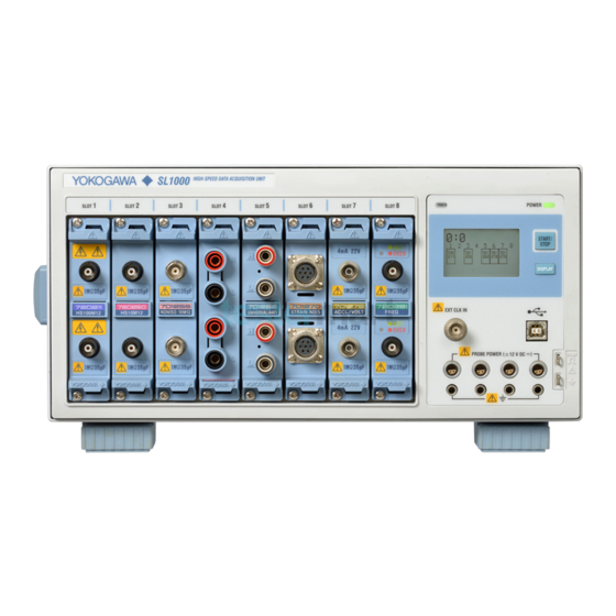
Page 21: Front Panel And Rear Panel
Names and Uses of Parts Front Panel and Rear Panel Front Panel Handle Input module installation slots Used to carry the SL1000. A total of 8 slots. For a description of the indicated → Section 3.1 For the procedure to install or remove information, see section 1.3. - Page 22 GO/NO-GO output terminals Delivers GO/NO-GO determination output signals. → Section 5.6 Note Be sure to use the DIP switch at the factory default setting. If you change the setting, the SL1000 may not operate properly. Factory default settings Status OFF IM 720120-01E...
-
Page 23: Keys And Indicators
Keys and Indicators POWER TRIG’D START/ STOP DISPLAY Name Function START/STOP key Starts or stops the measurement or measurement and recording. The key illuminates while measurement is in progress. ON: Measuring OFF: Stopped DISPLAY key Switches the screen. Module status screen, system error screen, and communication parameter screen POWER indicator Displays the power status. - Page 24 Display Screens The available SL1000 screens are the module status screen, error screen, and communication parameter screen. Startup or timeout DISPLAY DISPLAY DISPLAY Communication Module status Error screen parameter screen screen • At startup, the module status screen appears. • Press DISPLAY to switch screens.
- Page 25 For details on errors and messages, see section 6.2. Instrument No. Displays the SL1000 unit’s instrument number. IP address Displays the IP address setting of the SL1000. Date and time Displays the SL1000 unit’s date and time. YYYY/MM/DD hh:mm:ss Status icon Indicates the SL1000 status using icons.
-
Page 26: Chapter 2 Explanation Of Functions
Chapter 2 Explanation of Functions System Configuration and Block Diagram System Configuration • External clock input • External trigger input Internal hard disk (option) • Sync input • GO/NO-GO output • Trigger output • Alarm output • Sync output • USB interface •... - Page 27 2.1 System Configuration and Block Diagram Block Diagram Module Block Diagram CPU Block Diagram Acquisition Block Diagram Plug-in Module CH1 - CH16 720210(HS100M12), 720211(HS100M12) ACQ Memory FPGA 100MW Main Memory 128 MB Isolator Isolation Block 701250(HS10M12), 720250(HS10M12) 80 GB ATA-4 (Option) FPGA Isolator...
- Page 28 2.1 System Configuration and Block Diagram Signal Flow on the SL1000 The flow of the signal applied to the input terminal varies depending on the input module. Here, the High-Speed 100 MS/s, 12-Bit Isolation Module (720210 (HS100M12)) will used an example to describe the signal flow. (For details on the signal flow on each module, see the block diagram.)
-
Page 29: Input Modules
Input Modules The SL1000 supports the following input modules. MODEL Name Abbreviation 720210 High-Speed 100 MS/s, 12-Bit Isolation Module HS100M12 720211 High-Speed 100 MS/s, 12-Bit Isolation Module HS100M12 701250 High-Speed 10 MS/s, 12-Bit Isolation Module HS10M12 720250 High-Speed 10 MS/s, 12-Bit Isolation Module... -
Page 30: Operating Configuration
Operating Configuration Online Operation In this configuration, you connect the SL1000 to a PC via the USB or Ethernet (option) interface and use a dedicated software program to specify measurement conditions and carry out measurements. You use a dedicated software program to start or stop measurements. The SL1000 measures and holds the data in its acquisition memory, and the PC reads it. - Page 31 You cannot specify measurement conditions directly on the SL1000. To make measurements in the standalone configuration, specify the SL1000 measurement conditions online in advance. In standalone configuration, you can connect the SL1000 to a PC via the USB or Ethernet (option) interface after measurements are complete and read the measured data on a PC.
-
Page 32: Independent Operation And Synchronous Operation
Independent Operation and Synchronous Operation Independent Operation Independent operation refers to making measurements on a single SL1000. GROUP-ID (0 to F) UNIT-ID=0 Ethernet/USB • During independent operation, set the group ID to a value from 0 to F and the unit ID to 0. - Page 33 • Triggering The AND or OR logic of the master unit’s external trigger input and slave units’ trigger sources. When the SL1000 triggers, the trigger signal is transmitted from the master unit’s trigger output. • Alarms The AND or OR logic of the slave units’ channel alarm conditions or the OR logic of the slave units’...
-
Page 34: Chapter 3 Making Preparations For Measurements
If you notice any symptoms of trouble such as unusual odors or smoke coming from the instrument, immediately turn OFF the power switch and unplug the power cord. If these symptoms occur, contact your nearest YOKOGAWA dealer. Handle the Power Cord with Care Do not place objects on top of the power cord and keep it away from any heat sources. - Page 35 3.1 Handling Precautions Carry the Instrument Properly First, remove the power cord and connection cables. The instrument weighs approximately 6 kg without any modules installed and 9 kg when eight modules are installed. Carry the instrument by the handles as shown below or carry it with both hands. HI GH -S PE IS IT...
-
Page 36: Installing The Instrument
• Install the instrument so that you can immediately remove the power cord if an abnormal or dangerous condition occurs. CAUTION If you block the inlet or outlet holes on the SL1000, the SL1000 will become hot and maybreak down. French AVERTISSEMENT •... - Page 37 3.2 Installing the Instrument • Place the instrument in a horizontal position as shown below. • If you are installing the instrument on a slippery surface, attach the rubber feet (two pieces) to the rear feet on the bottom panel. Installation Conditions Install the instrument in a place that meets the following conditions: Well-Ventilated Location...
- Page 38 • In an unstable location. Storage Location • We strongly recommend you store the SL1000 in an environment with a temperature between 5 and 40°C and a relative humidity between 20 to 80%RH. • When storing the SL1000, avoid the following locations.
-
Page 39: Installing Modules
Installing Modules WARNING • To prevent electric shock and damage to the instrument, make sure to turn OFF the power before installing or removing an input module. • Check that the input cable is not connected to the input terminals before installing or removing an input module. - Page 40 3.3 Installing Modules French AVERTISSEMENT • Pour éviter tout risque de choc électrique et d’endommagement de l’instrument, veiller à mettre l’instrument hors tension avant d’installer ou de retirer des modules d’entrée. • Avant d’installer ou de retirer des modules d’entrée, vérifier que le câble d’entrée n’est pas connecté...
- Page 41 Switching the installed input module with a different module and turning ON the power initializes the settings on that channel. If you want to save the settings, use the SL1000 Acquisition Software to specify the save destination medium and save the settings. For details, see section 8.2 in the Acquisition Software User’s Manual IM720120-61E.
- Page 42 In addition, this instrument complies with 21 CFR 1040.10 and 1040.11 except for deviations pursuant to Laser Notice No. 50, dated June 24, 2007. High-Speed 100 MS/s, 12-Bit Isolation Module (720210 (HS100M12) and 720211 (HS100M12)) Index SL1000 H IG H -S IS IT IO N...
- Page 43 ≤ 1 mW If you use the instrument in a manner not specified in this manual, the protection provided by the instrument may be impaired. Yokogawa Electric Corporation assumes no liability for the customer’s failure to comply with these requirements.
-
Page 44: Connecting The Power Supply
OFF. • Pour éviter tout risque de choc électrique ou d’incendie, utiliser exclusivement le cordon d’alimentation fourni par YOKOGAWA et prévu pour l’instrument. • Relier l’instrument à la terre pour éviter tout risque de choc électrique. Brancher le cordon d’alimentation sur une prise de courant à... - Page 45 3.4 Connecting the Power Supply Connecting the Power Cord Check that the power switch on the rear panel is OFF. Connect the power cord plug to the power connector on the rear panel. Connect the plug on the other end of the power cord to the outlet that meets the conditions below.
- Page 46 SL1000 has started normally before you use it. If the SL1000 Does Not Start Normally When the Power Is Turned On Turn off the power switch, and check the following items. • Check that the power cord is securely connected.
-
Page 47: Connecting The Probes
D IS WARNING When connecting an item to be measured to the SL1000, be sure to turn OFF the power to the item. Connecting or disconnecting the measuring lead while the item being measured is turned ON is very dangerous. - Page 48 3.5 Connecting the Probes • To measure high voltage with the 720210 (HS100M12), 720211 (HS100M12), 701250 (HS10M12), 720250 (HS10M12), or 701251 (HS1M16), use the isolated probes (700929, 701947), passive probes 702902, or 1:1 safety cables (combination of 701901 and 701954). •...
- Page 49 3.5 Connecting the Probes • For the 701251 (HS1M16) Maximum input voltage (at a frequency of 1 kHz or less) • In combination with an isolated probe (10:1) 700929 or (100:1) 701947, or a passive probe (10:1) 702902 600 V (DC + ACpeak) •...
- Page 50 Over-Range Indication If over-range is indicated on the display of SL1000, the SL1000 may be receiving a voltage higher than the observed waveform or measured waveform values. To prevent electric shock, change the measuring range so that the entire amplitude of the waveform is displayed within the waveform display area of the SL1000 Acquisition Software, and check the input voltage level.
- Page 51 3.5 Connecting the Probes • Utilisez uniquement les câbles préconisés. Il est extrêmement dangereux d’utiliser des câbles n’étant pas conformes aux normes de sécurité. (notamment lorsque vous travaillez avec de hautes tensions de 42 V, voire supérieures). • Pour mesurer la tension élevée avec 720210 (HS100M12), 720211 (HS100M12), 701250 (HS10M12), 720250 (HS10M12) ou 701251 (HS1M16), utiliser des sondes isolées (700929, 701947), des sondes passives 702902 ou des câbles de sécurité...
- Page 52 3.5 Connecting the Probes Tension nominale maximale à la terre (à une fréquence 1 kHz ou inférieure) • En cas d’utilisation avec la sonde isolée 700929 (10:1) ou (100:1) 701947 ou la sonde passive 702902 (10:1) Ou si utilisé avec le câble de sécurité (1:1; 701901 et 701954 conjointement). 701250: 400 Vrms (Measurement Category Other (O)), 300 Vrms (CAT II) 720250: 400 Vrms (CAT II) •...
- Page 53 Dépassement de plage En cas de dépassement de plage indiqué à l’écran du SL1000, ce dernier risque de recevoir une tension supérieure à la forme d’onde observée ou aux valeurs de forme d’onde mesurées. Pour éviter tout choc électrique, modifiez la plage de mesure afin que l’amplitude totale de la forme d’onde s’affiche dans la zone...
- Page 54 3.5 Connecting the Probes Precautions to Be Taken When Connecting the Cable • When connecting a probe to the instrument for the first time, perform phase correction of the probe as described in section 3.6, “Compensating the Probe (Phase Correction).” Perform the phase correction for each channel to which a probe is to be connected.
- Page 55 ( 12 CAUTION Use the probe power supply (option) on the front panel of the SL1000 only to supply power to the current probes. Also, be sure to use only the number of probes allowed. Otherwise, the SL1000 or the device connected to the probe power supply terminal may break.
- Page 56 (current measured by the current probe). The characteristics of the measured current versus the current consumption of a current probe that can be connected to the SL1000 are shown below. Current probe (701930)
- Page 57 3.5 Connecting the Probes Connecting Differential Probes When using Yokogawa differential probes (700924, 700925, 701926), connect the BNC output connector to the oscilloscope’s input terminal. Also, be sure to connect the GND lead to the functional ground terminal of the DL850E/DL850EV. If necessary, use the auxiliary grounding lead extension.
-
Page 58: Compensating The Probe (Phase Correction)
Compensating the Probe (Phase Correction) When making measurements using a probe on the following modules, be sure to perform phase correction of the probe first. • High-Speed 100 MS/s, 12-Bit Isolation Module: 720210 (HS100M12) and 720211 (HS100M12) • High-Speed 10 MS/s, 12-Bit Isolation Module: 701250 (HS10M12) and 720250 (HS10M12) •... - Page 59 3.6 Compensating the Probe (Phase Correction) Explanation Why Phase Correction of the Probe Is Necessary The probe comes with its phase corrected approximately to match the input capacitance of the relevant measuring instrument. However, there is some error in the input resistance and input capacitance of each input channel of individual measuring instruments.
-
Page 60: Connecting Measuring Leads
L (black) WARNING • When connecting an item to be measured to the SL1000, be sure to turn OFF the power to the item. Connecting or disconnecting the measuring lead while the item being measured is turned ON is very dangerous. - Page 61 (Black) Over-Range Indication If over-range is indicated on the display of SL1000, the SL1000 may be receiving a voltage higher than the observed waveform or measured waveform values. To prevent electric shock, change the measuring range so that the entire amplitude of the waveform is displayed within the waveform display area of the SL1000 Acquisition Software, and check the input voltage level.
- Page 62 3.7 Connecting Measuring Leads French AVERTISSEMENT • Toujours mettre l’appareil à mesurer hors tension avant de le brancher sur l’instrument. Il est extrêmement dangereux de brancher un câble de mesure lorsque l’appareil à mesurer est sous tension. • Ne pas relier une borne de type enfichable, avec des parties conductrices exposées, à...
- Page 63 (Noir) Dépassement de plage En cas de dépassement de plage indiqué à l’écran du SL1000, ce dernier risque de recevoir une tension supérieure à la forme d’onde observée ou aux valeurs de forme d’onde mesurées. Pour éviter tout choc électrique, modifiez la plage de mesure afin que l’amplitude totale de la forme d’onde s’affiche dans la zone...
-
Page 64: Connecting Thermocouples
Compensation lead (or thermocouple wire) WARNING If over-range is indicated on the display of SL1000, the SL1000 may be receiving a voltage higher than the observed waveform or measured waveform values. To prevent electric shock, check the input voltage level. - Page 65 French AVERTISSEMENT En cas de dépassement de plage indiqué à l’écran du SL1000, ce dernier risque de recevoir une tension supérieure à la forme d’onde observée ou aux valeurs de forme d’onde mesurées. Pour éviter tout choc électrique, vérifiez la tension d’entrée.
-
Page 66: Connecting A Bridge Head
Connecting a Bridge Head Strain is measured by connecting a strain gauge bridge (bridge head) or a strain gauge transducer to the strain module (701270 (STRAIN_NDIS) or 701271 (STRAIN_DSUB)). This section will mainly describe the procedures and precautions related to the connection of the bridge head (Model 701955, 701956, 701957, and 701958). - Page 67 If Using a Bridge Head with a MIL Standard (MIL-C-26482) Connector Wiring The connector on the 701270 (STRAIN_NDIS) is an NDIS connector.* Use a connector adapter cable (700935) by YOKOGAWA to make a MIL-NDIS conversion and connect the bridge head to the Strain Module (701270).
- Page 68 3.9 Connecting a Bridge Head If Using the A1002JC Connector by YOKOGAWA You can create your own cable by using the YOKOGAWA A1002JC connector that is compatible with the strain module and use the cable to connect a strain gauge bridge or a strain gauge transducer to the strain module.
-
Page 69: 3.10 Connecting Acceleration Sensors
(ACCL/VOLT). For a details on acceleration sensors, see the respective manuals. WARNING If over-range is indicated on the display of SL1000, the SL1000 may be receiving a voltage higher than the observed waveform or measured waveform values. To prevent electric shock, change the measuring range so that the entire amplitude of the waveform is displayed within the waveform display area of the SL1000 Acquisition Software, and check the input voltage level. - Page 70 The acceleration signal (charge signal) that has been Index converted to a voltage signal by the charge amplifier is applied to the SL1000 using a normal coaxial cable. The SL1000 measures the signal in the voltage measurement mode.
- Page 71 The SL1000 measures the signals in the acceleration measurement mode and supplies bias current to the charge converter. Set the input sensitivity of the SL1000 according to the charge converter gain and the sensitivity of the charge output type acceleration sensor.
-
Page 72: 3.11 Connecting Sensors To The Frequency Module
Pull-up 5V WARNING If over-range is indicated on the display of SL1000, the SL1000 may be receiving a voltage higher than the observed waveform or measured waveform values. To prevent electric shock, change the measuring range so that the entire amplitude of the waveform is displayed within the waveform display area of the SL1000 Acquisition Software, and check the input voltage level. - Page 73 Connecting the Electromagnetic Pickup • SL1000 allows power-generating electromagnetic pickup to be connected directly. SL1000 does not support electromagnetic pickups that require external power supply or those that require a terminator at the output. • To connect electromagnetic pickups, use BNC cables. Use cables that are appropriate for the electromagnetic pickups being used.
-
Page 74: Chapter 4 Starting/Stopping Measurements
Note Remove the USB cable that is connecting the SL1000 to the PC only after you have exited the Acquisition Software or after you have disconnected the communication between the SL1000 and the PC. For details, see the Acquisition Software User’s Manual IM720120-61E. - Page 75 4.1 Connecting to a PC Connecting Using the Ethernet Interface (Option) Ethernet Interface Specifications There is a 1000BASE-T port on the rear panel of the SL1000. Item Specifications Number of Ethernet ports Electrical and mechanical Conforms to IEEE802.3 specifications Transmission system...
- Page 76 Avoid connecting the PC directly to the SL1000 without going through the hub or router. Operations are not guaranteed for communications using direct connection. • You can connect the SL1000 to a network that has DHCP turn ON without having to change the Ethernet settings of the SL1000. •...
- Page 77 Rotary switch (UNIT) positions 8 and 9 are invalid. • The group and unit IDs are not changed while the SL1000 is turned ON. To change the group or unit ID, set them after you turn OFF the SL1000. •...
- Page 78 4.1 Connecting to a PC Independent operation GROUP-ID (0 to F) UNIT-ID=0 Ethernet/USB Synchronous Operation Ethernet/USB Same GROUP-ID (0 to F) Master Slave #1 Slave #2 Slave #7 UNIT-ID=0 UNIT-ID=1 UNIT-ID=2 UNIT-ID=7 SYNC OUT SYNC IN SYNC OUT SYNC IN SYNC OUT SYNC IN Note...
-
Page 79: Starting/Stopping Measurements
Starting/Stopping Measurements You start or stop measurements in standalone mode. You can carry out this procedure during independent operation or on the master unit during synchronous operation. For the operating procedures in online mode, see the Acquisition Software User’s Manual IM720120-61E. Procedure Starting the Measurement Note... -
Page 80: Chapter 5 External I/O Terminals
SL1000, à cause de facteurs tels que la surtension. External Clock Input Terminal Use this terminal if you want to operate the SL1000 using an external clock signal. EXT CLK IN Item... -
Page 81: Connecting The External Trigger Input Terminal (Trig In)
French ATTENTION Appliquer uniquement des signaux respectant les spécifications ci-dessous. Les signaux ne respectant pas les spécifications risquent d’endommager SL1000, à cause de facteurs tels que la surtension. External Trigger Input Terminal Use this terminal to use an external signal for the trigger source. -
Page 82: Connecting The Trigger Output Terminal (Trig Out)
Connecting the Trigger Output Terminal (TRIG OUT) CAUTION Do not apply external voltage to the TRIG OUT terminal. If you do, the SL1000 may malfunction. French ATTENTION Ne pas court-circuiter la borne TRIG OUT et ne pas appliquer de tension de sortie. - Page 83 5.3 Connecting the Trigger Output Terminal (TRIG OUT) Hold Time of the Low and High Level Signals Trigger occurrence Trigger occurrence Trigger output Post time Trigger Trigger Pre-trigger Post-trigger Pre-trigger Post-trigger Waveform acquisition IM 720120-01E...
-
Page 84: Connecting The Alarm Output Terminals (Alarm)
• Do not apply external voltage to the alarm output terminals. If you do, the SL1000 may malfunction. • Do not short between alarm output terminals. If you do, the SL1000 may malfunction. • Be sure to turn OFF the power switch when connecting (or removing) signal wires to the alarm output terminals. - Page 85 To remove a signal wire, press down on the top section of the screwless terminal with a flat-blade screwdriver and pull the wire out. Note the top section of the screwless Be sure to hold the SL1000 firmly while pressing down on terminal with a flat-blade screwdriver. Use the following signal wires for the alarm output.
-
Page 86: Connecting The Remote Input Terminals (Remote)
CAUTION • Only input signals that meet the specifications below. Otherwise, undesirable signal such as excessive voltage may damage the SL1000. • Be sure to turn OFF the power switch when connecting (or removing) signal wires to the remote input terminals. - Page 87 5.5 Connecting the Remote Input Terminals (REMOTE) Note the top section of the screwless Be sure to hold the SL1000 firmly while pressing down on terminal with a flat-blade screwdriver. Use the following signal wires for the remote input. • Signal wire thickness (single wire): ϕ0.4 to 1.0 (AWG26 to 18)
-
Page 88: Connecting The Go/No-Go Output Terminals
• Do not apply external voltage to the GO/NO-GO output terminals. If you do, the SL1000 may malfunction. • Do not short between GO/NO-GO output terminals. If you do, the SL1000 may malfunction. • Be sure to turn OFF the power switch when connecting (or removing) signal wires to the GO/NO-GO output terminals. - Page 89 To remove a signal wire, press down on the top section of the screwless terminal with a flat-blade screwdriver and pull the wire out. Note the top section of the screwless Be sure to hold the SL1000 firmly while pressing down on terminal with a flat-blade screwdriver. Use the following signal wires for the GO/NO-GO output.
-
Page 90: Sync I/O Connectors (Sync In And Sync Out)
• Do not apply external voltage to the sync output connector. If you do, the SL1000 may malfunction. • Do not short the sync output connector terminals. If you do, the SL1000 may malfunction. • Be sure to turn off the power switch when connecting or disconnecting sync cables from the sync I/O connectors. - Page 91 5.7 Sync I/O connectors (SYNC IN and SYNC OUT) Synchronous Operation Connect the sync I/O connectors (SYNC IN and SYNC OUT) of multiple SL1000s using sync cables in a daisy-chain pattern. Ethernet/USB Master Slave #1 Slave #2 Slave #7 UNIT-ID=0 UNIT-ID=1 UNIT-ID=2 UNIT-ID=7...
- Page 92 5.7 Sync I/O connectors (SYNC IN and SYNC OUT) Note • For details on the synchronous operation feature, see section 2.4. • For the procedure to set the group ID and unit ID, see section 4.1. • For the synchronous operation procedure and notes about using the Acquisition Software, see the Acquisition Software User’s Manual IM720120-61E.
-
Page 93: Chapter 6 Maintenance
– Trigger does not activate. The trigger settings are not appropriate. Set the trigger conditions correctly. Measured values are not Insufficient warm-up. Warm up the SL1000 for 30 minutes after – correct. turning ON the power. Not calibrated. Perform a calibration. -
Page 94: Codes And Corrective Actions
An error code may appear on the screen during operation. This section describes the meanings of the messages and their corrective actions. If the corrective action indicates servicing, contact your nearest YOKOGAWA dealer for repairs. In addition to the error codes below, there are Acquisition Software error messages. - Page 95 6.2 Codes and Corrective Actions System Errors Type Code Description Corrective Action Reference Section Failed to backup setup data. Servicing is required. Section 6.3 Will initialize. Backup battery may be low. Buffer overrun occurred. Could not write data within a specified time. Lower the sample rate or reduce the number IM720120-61E Buffer overrun occurred on internal hard disk.
-
Page 96: Recommended Replacement Parts
Internal hard disk One year after purchase (data is excluded) The following items are expendable items. We recommend that you replace them according to the period indicated below. Contact your nearest YOKOGAWA dealer to have parts replaced. Parts Name Recommended Replacement Period... -
Page 97: Chapter 7 Specifications
Effective display screen size 45.2 mm × 27.0 mm Display resolution 128 × 64 Displayed contents Common area • SL1000 group ID and unit ID • Status icons Displays the following information one at a time (switched by pressing DISPLAY) • Module status • Error information •... -
Page 98: External I/O Section
External I/O Section External Clock Input (EXT CLK IN) Item Specifications Connector type Input level TTL (0 to 5 V) Valid edge Rising edge Minimum pulse width 100 ns or more for high and low External clock frequency 5 MHz maximum range Sampling jitter Within (100 ns + 1 sample period) -
Page 99: Computer Interface
7.4 External I/O Section / 7.5 Computer Interface / 7.6 Synchronous Operation COMP Output (Rectangular Signal Output for Probe Compensation) Item Specifications Output frequency 1 kHz ± 1% Output amplitude 1 Vp-p ± 10% Probe Power Output (/P4 Option) Item Specifications Number of output terminals 4 Output voltage... -
Page 100: General Specifications
319 mm (W) × 154 mm (H) × 350 mm (D) (excluding projections) Weight Approx. 6 kg (the SL1000 only) Approx. 9 kg (the SL1000 + eight High-Speed 100 MS/s, 12-Bit Isolation Modules) Cooling method Forced air cooling, inlet on the right and bottom panels, exhaust from the rear panel... - Page 101 When connecting 701904 to a module, attach a ferrite core (TDK: ZCAT2035-0930A, YOKOGAWA: A1190MN) to the SL1000 end of the cable. When connecting a probe to a module, pass the SL1000 end of the cable twice through the ferrite core (TDK: ZCAT2035-0930A, YOKOGAWA: A1190MN).
- Page 102 700987, 701955, 701956, 701957, 701958) 1. If the 701260 module is inserted into the SL1000, it will not comply with safety standard EN61010-1:2010 or EN61010-2-030:2010. 2. The Overvoltage Category (Installation Category) is a value used to define the transient overvoltage condition and includes the impulse withstand voltage regulation.
- Page 103 4. Pollution Degree: Applies to the degree of adhesion of a solid, liquid, or gas which deteriorates withstand voltage or surface resistivity. Pollution Degree 2 applies to normal indoor atmospheres (with only non-conductive pollution). 5 If the 701260 or 701280 module is inserted into the SL1000, it will not comply with environment regulation standard EN50581:2012.
-
Page 104: External Dimensions
External Dimensions SL1000 Unit: mm Rear View 28.5 ±5 Unless otherwise specified, tolerance is ±3% (however, tolerance is ±0.3 mm when below 10 mm). IM 720120-01E... -
Page 105: Appendix
Appendix Appendix 1 TCP and UDP Port Numbers Used in Ethernet Communications The TCP and UDP port numbers that the SL1000 Ethernet interface uses are as follows: TCP Port Numbers That the SL1000 Uses Port Number Description Function File Transfer [Default Data]... - Page 106 Index Symbol frequency module, LEDs ............ 3-10 Page front panel................1-1 1000BASE-T port ..............4-2 FTP connection ..............2-6 functional ground terminal ............ 1-1 Page Page acceleration sensor ............3-36 accessories................iv, vi general specifications ............7-4 acquisition memory............... 2-5 GO icon ................
- Page 107 Index Page Page phase compensation ............3-24 UDP port numbers ............App-1 phase compensation signal ..........3-25 unit ID ................1-5, 4-4 power consumption ............3-12 USB ..................2-5 power cord ................3-12 USB connection ............. 4-1, 7-3 POWER indicator ..............1-3 USB connector for a PC ............
Need help?
Do you have a question about the SL1000 and is the answer not in the manual?
Questions and answers