Table of Contents
Advertisement
Quick Links
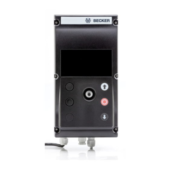
BDC-i440 M3
Assembly and Operating Instructions
en
M3 module for BDC-i440 control units
Important information for:
• Fitters / • Electricians / • Users
Please forward accordingly!
These instructions must be kept safe for future reference.
4041 630 049 0 15/10/2018
Becker-Antriebe GmbH
Friedrich-Ebert-Straße 2-4
35764 Sinn/Germany
www.becker-antriebe.com
Advertisement
Table of Contents

Subscribe to Our Youtube Channel
Summary of Contents for Becker M3
- Page 1 BDC-i440 M3 Assembly and Operating Instructions M3 module for BDC-i440 control units Important information for: • Fitters / • Electricians / • Users Please forward accordingly! These instructions must be kept safe for future reference. 4041 630 049 0 15/10/2018 Becker-Antriebe GmbH Friedrich-Ebert-Straße 2-4...
-
Page 2: Table Of Contents
Table of contents General ........................ 3 Warranty ...................... 3 Safety instructions .................... 4 Intended use ...................... 6 Functions ...................... 6 Assembly ...................... 9 Installation and function of the NFC module (optional).......... 10 Wiring ......................... 11 Technical data ..................... 14 Declaration of conformity .................. 15... -
Page 3: General
General The M3 module is a high-quality product with the following performance characterist- ics: • Evaluation of additional safety devices on the door (e.g. light barrier, light grids and similar) • Evaluation of safety devices with 8k2 terminating resistor (e.g. for wicket door, safety edge, slack rope switch and similar) •... -
Page 4: Safety Instructions
Safety instructions The following safety instructions and warnings are intended to avert hazards and to prevent property damage and personal injury. It is important to follow these instruc- tions. General information • In addition to the fire and accident prevention regulations, the safety instructions given in EN 12453, EN 12978, VDE 0100, EN 50110, EN 60204, EN 50178, EN 60335 and ASR A1.7 must be observed. - Page 5 approved third-party products, or modifications which have not been agreed with or approved by us, are prohibited. We do not ac- cept liability for damage or injury arising from such actions. • Before connecting the power supply to the control unit for the first time, you must ensure that the evaluation circuit boards (plug-in modules) are plugged into the correct position.
-
Page 6: Intended Use
Intended use The M3 module is intended solely for the expansion of the BDC control unit and can only be operated with these control units. The M3 module is installed in the BDC hous- ing. Please strictly observe the Assembly and Operating Instructions for the master control unit in relation to the commissioning, operation and repair of the sys- tem. - Page 7 DIP switch Once the DIP switch has been set, the BT_NA button must be pressed and held (>2 s). This stores the current state of the DIP switch. Switch Position Function SE3 terminating resistor 8k2 DIP 1 FE3 digital evaluation SE4 terminating resistor 8k2 DIP 2 FE4 digital evaluation...
- Page 8 Relays being operated are indicated by means of the corresponding LED. Fault / diagnosis If a communication fault or an internal error occurs on the M3 module, the control unit switches to dead-man mode. An error is indicated by means of E.408 in the control unit.
-
Page 9: Assembly
Relays being operated are indicated by means of the corresponding LED. Fault / diagnosis If a communication fault or an internal error occurs on the M3 module, the control unit switches to dead-man mode. An error is indicated via F.782 in the control unit. An act- ive input is indicated via E.121 –... -
Page 10: Installation And Function Of The Nfc Module (Optional)
Installation and function of the NFC module (optional) Using the Becker Service APP and the NFC module you can read out the serial number, version, error messages, clock cycles, operating hours and parameters on the master control unit. The data can also be read out when the control unit is off. -
Page 11: Wiring
Wiring The electrical connection of the supply voltage is carried out by the relevant available BDC control unit. The power supply is indicated by means of the 24 V LED on the M3 module. Relay / contactor control unit The M3 module is connected to the type R and type S BDC control units using the pin strip with the enclosed ten-pin flat ribbon cable. - Page 12 Frequency converter control unit The M3 module is connected to the frequency converter control unit using the X6 ter- minal on the M3 and X20a on the frequency converter control unit with the enclosed five-pin cable. Relaying of inputs SE3 - SE6 To relay inputs SE3 –...
- Page 13 Speed monitoring of the absolute value encoder To relay inputs SE3 – SE6, DIP switches 5 and 6 must be set to ON. For speed monitoring of the absolute value en- coder, set DIP switch 5 to ON and DIP switch 6 to OFF. BT_NA 1 2 3 4 5 6 7 8 X502 1...
-
Page 14: Technical Data
Technical data Additional technical data for the master control unit Dimensions of board 157mm x 86mm Supply voltage 24 V DC, 12 V DC Power consumption of the con- 100 mA with a full load trol unit Relay Rel4-NA For inductive switching loads, suitable interference suppression measures should be put in place NO contact, floating µ... -
Page 15: Declaration Of Conformity
Declaration of conformity...


Need help?
Do you have a question about the M3 and is the answer not in the manual?
Questions and answers