Table of Contents
Advertisement
www.acornfiresecurity.com
Engineering and Commissioning Manual
Fire Detection & Alarm System Control Panel
Doc. 26-0959
Rev. 15
www.acornfiresecurity.com
(Suitable for control panels from V3.00)
SOLUTIONS
Fire Protection
Explosion Protection
Overpressure Protection
Pressure Activation
26-0959 Issue 14 Draft
Advertisement
Table of Contents

Related Manuals for Fike Twinflex pro2


Summary of Contents for Fike Twinflex pro2
- Page 1 www.acornfiresecurity.com Engineering and Commissioning Manual Fire Detection & Alarm System Control Panel (Suitable for control panels from V3.00) Doc. 26-0959 Rev. 15 SOLUTIONS Fire Protection Explosion Protection Overpressure Protection Pressure Activation 26-0959 Issue 14 Draft www.acornfiresecurity.com...
- Page 2 Fike’s policy is one of continual improvement and the right to change a specification at any time without notice is reserved. Whilst every care has been taken to ensure that the contents of this document are correct at time of publication, Fike shall be under no liability whatsoever in respect of such contents.
-
Page 3: Table Of Contents
www.acornfiresecurity.com ® TWINFLEX pro² Control Panel Engineering and Commissioning Manual Contents Introduction .......................... 5 System Design ......................5 Equipment Guarantee ....................5 Anti Static Handling Guidelines ................5 Warning ........................5 EMC .......................... 6 The TWINFLEX®pro² System ..................... 6 Control Panel ........................7 Mounting the Control Panel .................. - Page 4 www.acornfiresecurity.com ® TWINFLEX pro² Control Panel Engineering and Commissioning Manual Installation and Commissioning ..................60 Installation 1st Stage ....................60 Installation 2nd Stage ....................60 Commissioning ......................61 End User Training ..................... 61 Maintenance ......................61 Fault Finding ........................62 Summary of Faults....................
-
Page 5: Introduction
Failure to do so may result in damage to the equipment and could invalidate the warranty. For technical support please contact your distributor. Do not call the Fike Safety Technology support department unless your distributor has first given their advice and attempted to rectify the issue. -
Page 6: Emc
www.acornfiresecurity.com ® TWINFLEX pro² Control Panel Engineering and Commissioning Manual This equipment when installed is subject to the EMC directive 2014/108/EC. It is also subject to UK Statutory Instrument 2006 No. 3418. To maintain EMC compliance, this system must be installed as defined within this manual. Any deviation from this renders the installer liable for any EMC problems that may occur either to the equipment or to any other equipment affected by the installation. -
Page 7: Control Panel
www.acornfiresecurity.com ® TWINFLEX pro² Control Panel Engineering and Commissioning Manual Control Panel Mounting the Control Panel First identify the proposed location for the control panel. Ensure that the control panel will be easily accessible and that account is taken of any subsequent work that may affect access. The control panel should be located at the most likely point of access for the fire services. -
Page 8: Power Supply Unit
www.acornfiresecurity.com ® TWINFLEX pro² Control Panel Engineering and Commissioning Manual Power Supply Unit The mains supply should be dedicated to the Fire Alarm Panel and should be clearly labelled ‘FIRE ALARM: DO NOT SWITCH OFF’ at all isolation points. The Fire Alarm Panel 230V AC supply requires a 3 amp with local isolation and fixed wiring between 0.75 mm and 2.5 mm... -
Page 9: General Assembly
(at the SCRN terminal provided, not at any earthing point). Do not connect the screen to any device back box used other than those supplied by Fike. 3. The cable screen continuity must be maintained at every point of the circuit, using the terminals provided or a suitable connection block. -
Page 10: System Wiring Schematic
www.acornfiresecurity.com ® TWINFLEX pro² Control Panel Engineering and Commissioning Manual System Wiring Schematic The following schematic may prove useful as an aid to understanding the cable requirements for the system; ® 1-8 TWINFLEX zones. Cabled in 2 core 1.5mm Screened cable complying with BS 5839: Pt 1: 2017 Category 1. -
Page 11: Control Panel Connections
www.acornfiresecurity.com ® TWINFLEX pro² Control Panel Engineering and Commissioning Manual Control Panel Connections TERMINAL DESCRIPTION Overview- 2 zone panel USB-B USB-B CONNECTION FOR PC LINK MONITORED I/P Monitored Input positive connection MI1 + Monitored Input 0V connection MI1 - Field cable screen connection SCRN PROG I/P 1+2 Programmable Input positive connection... -
Page 12: Overview - 4 / 8 Zone Panel
www.acornfiresecurity.com ® TWINFLEX pro² Control Panel Engineering and Commissioning Manual Overview – 4 / 8 zone Panel TERMINAL DESCRIPTION USB-B USB-B CONNECTION FOR PC LINK NETWORK NET A Peripheral Bus Connections NET B Peripheral Bus Connections SCRN Peripheral Bus Connections NET A Peripheral Bus Connections NET B... -
Page 13: Monitored Input Wiring
www.acornfiresecurity.com ® TWINFLEX pro² Control Panel Engineering and Commissioning Manual Monitored Input: MI1+, MI1-, SCRN ON BOARD PCB FIELD CONNECTIONS MI1 + N/O CONTACT MI1 - 3k3 EOL SCREEN 680Ω SCREEN Maximum Voltage at contacts, 3.3 Volts. Maximum current 10mA. Monitored Input 1 may be configured to monitor for open and short circuit faults using a 3k3 EOL resistor and to activate an alarm using a 680Ω... -
Page 14: Twinflex Device Zones Wiring
(at the SCRN terminal provided, not at any earthing point). Do not connect the screen to any device back box used other than those supplied by Fike. 3. The cable screen continuity must be maintained at every point of the circuit, using the terminals provided or a suitable connection block. -
Page 15: Conventional Device Zones Wiring
(at the SCRN terminal provided, not at any earthing point). Do not connect the screen to any device back box used other than those supplied by Fike. 3. The cable screen continuity must be maintained at every point of the circuit, using the terminals provided or a suitable connection block. -
Page 16: Fault Relay
www.acornfiresecurity.com ® TWINFLEX pro² Control Panel Engineering and Commissioning Manual Fault Relay: C, N/C, N/O ON BOARD PCB FIELD CONNECTIONS COMMON NORMALLY CLOSED NORMALLY OPEN The fault relay is derived from a single pole change over ‘volt-free’ relay contact which is not fault monitored. -
Page 17: Monitored Outputs 1 & 2
www.acornfiresecurity.com ® TWINFLEX pro² Control Panel Engineering and Commissioning Manual Monitored Outputs 1 and 2: MO+, MO-, SCRN ON BOARD PCB FIELD CONNECTIONS 10k EOL MO - SCREEN SCREEN SCREEN Outputs 1 and 2 are monitored circuits which may be configured to monitor for open and short circuit faults with a 10k EOL resistor. -
Page 18: Batteries
Batteries should be connected in series as per the diagram. For extended backup times an external battery box can be purchased from Fike Safety Technology Part No 505-0020. This includes extended battery connection leads. This requires 2 x 12V 7.0Ah – 7.2Ah batteries. -
Page 19: Write Protect / Write Enable Switch
www.acornfiresecurity.com ® TWINFLEX pro² Control Panel Engineering and Commissioning Manual Write Protect / Write Enable Switch Note: 4 Zone / 8 Zone Panel version shown The write protect / write enable switch is a two position switch which is normally set to stop options in the engineer menu from being inadvertently changed. -
Page 20: Zone Twinflex Expansion Card
www.acornfiresecurity.com ® TWINFLEX pro² Control Panel Engineering and Commissioning Manual 8 Zone Expansion Card The 8 zone panel contains an 8 zone expansion PCB. This will already have been set up in the factory and programming options for the extra zones will be enabled. This card is not present in the 2-zone or 4-zone versions of the panel. -
Page 21: General Operation Of Control Panel
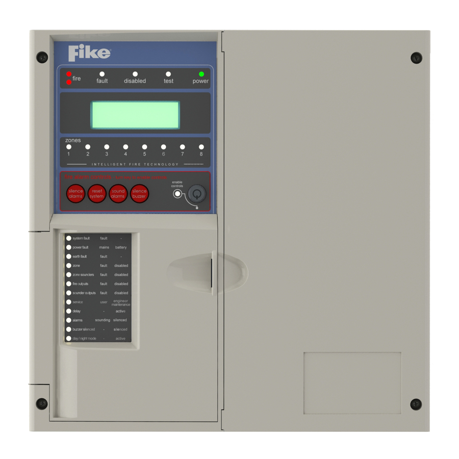
www.acornfiresecurity.com ® TWINFLEX pro² Control Panel Engineering and Commissioning Manual General Operation of Control Panel Control Panel Front Note : 4 Zone / 8 Zone Panel version shown General Indication LEDs Control Panel Information Window Zonal Indication LEDs Fire Alarm Controls / Controls Enabled Keyswitch System Indication LEDs System Controls... -
Page 22: Led Indication
www.acornfiresecurity.com ® TWINFLEX pro² Control Panel Engineering and Commissioning Manual LED Indication Note : 4 Zone / 8 Zone Panel version shown The operation of the LED indication on the front of the control panel is described below. The LED indication on the panel can also be confirmed by checking the message displayed in the panel information screen or by accessing the relevant event log from the panel menu. -
Page 23: Access Levels And Codes
www.acornfiresecurity.com ® TWINFLEX pro² Control Panel Engineering and Commissioning Manual ZONE SOUNDERS Flashing A fault condition is present on a Twinflex zone circuit. A device or an action associated with the zone Yellow Continuous sounder circuits has been disabled. Flashing A fault condition is present on the monitored fire FIRE OUTPUTS Yellow... -
Page 24: Fire Alarm Controls
www.acornfiresecurity.com ® TWINFLEX pro² Control Panel Engineering and Commissioning Manual Fire Alarm Controls Note : 4 Zone / 8 Zone Panel version shown The main Fire Alarm Controls may be enabled by turning the key switch to the controls enabled position to go from access level 1 to AL2A, or by entering a valid access code to all modes above AL1. -
Page 25: Access Level 1 (Normal)
www.acornfiresecurity.com ® TWINFLEX pro² Control Panel Engineering and Commissioning Manual Access Level 1 (Normal): Controls Enabled LED off At Access Level 1 (Normal), the main Fire Alarm Controls are disabled and the following System Controls will only be accessible if a fire, fault or disablement is active on the panel: NORMAL 1. -
Page 26: Access Level 2A (User)
www.acornfiresecurity.com ® TWINFLEX pro² Control Panel Engineering and Commissioning Manual Access Level 2A (User): Enable Controls LED on At Access Level 2A (User), the main Fire Alarm Controls are enabled and the following System Controls are accessible: USER (8737) 1. View Current Events 1. - Page 27 www.acornfiresecurity.com ® TWINFLEX pro² Control Panel Engineering and Commissioning Manual 1. View Current Events 4. Current Warnings The Active Log will display any current warnings. These are displayed 01/09/09 22:26 USER in text format and may be scrolled through by pressing the UP and DOWN keys.
-
Page 28: Access Level 2B (Supervisor)
www.acornfiresecurity.com ® TWINFLEX pro² Control Panel Engineering and Commissioning Manual Access Level 2B (Supervisor ): Enable Controls LED flashing slowly At Access Level 2B (Supervisor), the main Fire Alarm Controls are enabled and the following System Controls are accessible. Note: A system reset must be done after any changes are made in order for them to take effect. SUPR (7877) 1. - Page 29 www.acornfiresecurity.com ® TWINFLEX pro² Control Panel Engineering and Commissioning Manual 1. View Current Events 1. Current Fires The Active Log will display any current fires. These are displayed in FIRE 001 OF 001 text format and may be scrolled through by pressing the UP and Z01: ZONE 01 DOWN keys.
- Page 30 www.acornfiresecurity.com ® TWINFLEX pro² Control Panel Engineering and Commissioning Manual 1. Test Cntrls & Disp 2. Test Modes 3. Test Buzzer The Test Buzzer function toggles on and off to ensure correct buzzer 01/09/09 22:26 SUPR operation unless the buzzer has been disabled by fitting a jumper link BUZZER TESTING..
- Page 31 www.acornfiresecurity.com ® TWINFLEX pro² Control Panel Engineering and Commissioning Manual 2. Test Modes 2. Test Zone 3. System Test The System Test function allows the entire system to operate in a 01/09/09 22:26 SUPR simple one-man walk test mode. On triggering a device the device LED SYSTEM TEST (ZONES) operates, all the assigned sounders operate for 10 seconds and the ENTER ZONE:00...
- Page 32 www.acornfiresecurity.com ® TWINFLEX pro² Control Panel Engineering and Commissioning Manual 5. Peripheral Buss 3. Enable/ Disable This allows the Peripheral Buss to be switched on or off. 01/09/09 22:26 SUPR Note: Ancillary equipment e.g. repeaters connected to the PERIPH BUSS: OFF peripheral bus do not meet EN 54-2 requirements.
-
Page 33: Access Level 3 (Engineer)
www.acornfiresecurity.com ® TWINFLEX pro² Control Panel Engineering and Commissioning Manual Access Level 3 (Engineer): Controls Enabled LED flashing quickly At Access Level 3A (Engineer), the main Fire Alarm Controls are enabled, and the following System Controls are accessible. To change options contained within the engineer menu, enter Access Level 3B. - Page 34 www.acornfiresecurity.com ® TWINFLEX pro² Control Panel Engineering and Commissioning Manual 1. All Event Logs 5. View Logs 2. Fire Logs 3. Fault Logs 4. Panel Event Logs 6. Zones 1. Zone Status 2. Zone Description 3. Zone Mode 1. Set Zone Type 7.
- Page 35 www.acornfiresecurity.com ® TWINFLEX pro² Control Panel Engineering and Commissioning Manual 10. Panel I/O 1. Programmable I/P 1 2. Programmable I/P 2 3. Monitored I/P 4. Monitored O/P 1 5. Monitored O/P 2 6. Fire Relay 7. Fault Relay 11. Peripheral Buss 1.
- Page 36 www.acornfiresecurity.com ® TWINFLEX pro² Control Panel Engineering and Commissioning Manual 1. View Current Events 2. Current Faults The Active Log will display any current faults. These are displayed in FAULT 001 OF 001 text format and may be scrolled through by pressing the UP and Z00: NA DOWN keys.
- Page 37 www.acornfiresecurity.com ® TWINFLEX pro² Control Panel Engineering and Commissioning Manual 2. Test Modes 1. Test Cntrl & Display 4. Test Keyboard The Test Keyboard function enables the user to select each button to 01/09/09 22:26 ENGR ensure the correct function on the screen. Press the ESC key TWICE KEYBOARD TESTING..
- Page 38 www.acornfiresecurity.com ® TWINFLEX pro² Control Panel Engineering and Commissioning Manual 2. Test Modes 3. Activate Outputs 1. Fire Relay Within this menu; selecting option 1. ON will turn on the fire 01/09/09 22:26 ENGR relay and selecting option 2. OFF, will turn the fire relay off. FIRE RELAY: OFF If the fire relay is left in the ON or OFF condition and the 1.ON...
- Page 39 www.acornfiresecurity.com ® TWINFLEX pro² Control Panel Engineering and Commissioning Manual 2. Test Modes 4. Test inputs 3. Monitored I/P 01/09/09 22:26 ENGR This will test monitored input and when it is triggered MON I/P TESTING. INPUT ACTIVATED will be displayed on line 3 of the INPUT ACTIVATED display.
- Page 40 www.acornfiresecurity.com ® TWINFLEX pro² Control Panel Engineering and Commissioning Manual 5. Peripheral Buss 3. Enable/ Disable 01/09/09 22:26 SUPR This allows the Peripheral Buss to be switched on or off. PERIPH BUSS: OFF Note: Ancillary equipment e.g. repeaters connected to the peripheral bus do not meet EN 54-2 requirements.
- Page 41 www.acornfiresecurity.com ® TWINFLEX pro² Control Panel Engineering and Commissioning Manual 6. Zones 1. Zone Status The Zone Status will display the current zone status of any zone 01/09/09 22:26 ENGR selected. These are displayed in text format and may be altered by ZONE STATUS (ON/OFF) pressing the LEFT and RIGHT keys.
- Page 42 www.acornfiresecurity.com ® TWINFLEX pro² Control Panel Engineering and Commissioning Manual 7. Alarm configuration 2. Confirmation Type This active control will allow the engineer to change the type of ‘alarm 01/09/09 22:26 ENGR confirmation’ implemented. Use the LEFT and RIGHT keys to toggle OPTION : ZONAL through the following options.
- Page 43 www.acornfiresecurity.com ® TWINFLEX pro² Control Panel Engineering and Commissioning Manual 8. Alarm Delay 2. Delay Fire Relay This active control will allow the engineer to set an alarm delay for the 01/09/09 22:26 ENGR panel fire relay. Use the LEFT and RIGHT keys to toggle through the FIRE RELAY: INSTANT following options.
- Page 44 www.acornfiresecurity.com ® TWINFLEX pro² Control Panel Engineering and Commissioning Manual 8. Alarm Delay 6. Zone of Origin Delay This active control will allow the engineer to automatically override any 01/09/09 22:26 ENGR delay in the zone of origin. Use the LEFT and RIGHT keys to toggle ORIGIN ZN : INSTANT through the following options.
- Page 45 www.acornfiresecurity.com ® TWINFLEX pro² Control Panel Engineering and Commissioning Manual 9. Panel Details 3. Software Version This active control will allow the engineer to view the version of panel 01/09/09 20:13 ENGR operating software implemented. SOFTWARE VERSION V1.04 Press Enter Key 9.
- Page 46 www.acornfiresecurity.com ® TWINFLEX pro² Control Panel Engineering and Commissioning Manual 9. Panel Details 5. Timers 1. Weekly Test Timer 3. Weekly Test Time This active control will allow the engineer to view or change the time of 01/09/09 20:13 ENGR 01/09/09 20:13 ENGR day at which the weekly test will be indicated.
- Page 47 www.acornfiresecurity.com ® TWINFLEX pro² Control Panel Engineering and Commissioning Manual 1. Control Event 10. Panel I/O 1. Programmable I/P 1 1. Input Type This active control will allow the engineer to view or change the 01/09/09 20:13 ENGR operation of the control event set for programmable input 1. Use the 1.SILENCE ALARMS UP and DOWN arrow keys to toggle through the following options.
- Page 48 www.acornfiresecurity.com ® TWINFLEX pro² Control Panel Engineering and Commissioning Manual 10. Panel I/O 1. Programmable I/P 1 1. Input Type 4. Disablement This active control will allow the engineer to view or change the 01/09/09 20:13 ENGR operation of the disablement event set for programmable input 1. Use 1.
- Page 49 www.acornfiresecurity.com ® TWINFLEX pro² Control Panel Engineering and Commissioning Manual 10. Panel I/O 2. Programmable I/P 2 1. Input Type This active control will allow the engineer to view or change the 01/09/09 20:13 ENGR operation of programmable input 2. Use the UP and DOWN arrow keys 1.CONTROL EVENT to toggle through the following options.
- Page 50 www.acornfiresecurity.com ® TWINFLEX pro² Control Panel Engineering and Commissioning Manual 10. Panel I/O 2. Programmable I/P 2 1. Input Type 2. Remote Fire Event This active control will allow the engineer to view or change the 01/09/09 20:13 ENGR operation of the remote fire event set for programmable input 2. Use 1.REMOTE FIRE- FULL the UP and DOWN arrow keys to toggle through the following options.
- Page 51 www.acornfiresecurity.com ® TWINFLEX pro² Control Panel Engineering and Commissioning Manual 10. Panel I/O 2. Programmable I/P 2 2. Description This option allows the engineer to change the text that will be displayed 01/09/09 22:26 ENGR on the panel when Programmable I/P 2 is activated. This is displayed EDIT PROGRAMABLE IP2 in text format and may be scrolled through by pressing the LEFT and NAME: PROG I/P 2...
- Page 52 www.acornfiresecurity.com ® TWINFLEX pro² Control Panel Engineering and Commissioning Manual 3. Monitored I/P 1. Control Event 10. Panel I/O 1. Input Type This active control will allow the engineer to view or change the 01/09/09 20:13 ENGR operation of the control event set for monitored input. Use the UP and 1.SILENCE ALARMS DOWN arrow keys to toggle through the following options.
- Page 53 www.acornfiresecurity.com ® TWINFLEX pro² Control Panel Engineering and Commissioning Manual 3. Monitored I/P 4. Disablement 10. Panel I/O 1. Input Type Programmable I/P 1 This active control will allow the engineer to view or change the 01/09/09 20:13 ENGR operation of the disablement event set for monitored input. Use the UP 1.
- Page 54 www.acornfiresecurity.com ® TWINFLEX pro² Control Panel Engineering and Commissioning Manual 10. Panel I/O 5. Monitored O/P 2 1. Output Type This active control will allow the engineer to view or change the 01/09/09 20:13 ENGR operation of Monitored O/P 2. Use the UP and DOWN arrow keys to 1.REMOTE SOUNDER toggle through the following options.
- Page 55 www.acornfiresecurity.com ® TWINFLEX pro² Control Panel Engineering and Commissioning Manual Note: Ancillary equipment e.g. repeaters connected to the 11. Peripheral Buss peripheral bus do not meet EN 54-2 requirements. 01/09/09 22:26 ENGR 1. PB RDU Supervise 1. PB Comm Configure Press Enter Key 1.
-
Page 56: Alarm Delays
www.acornfiresecurity.com ® TWINFLEX pro² Control Panel Engineering and Commissioning Manual Alarm Delays The following alarm outputs can be delayed for smoke detector alarms: Zone Outputs (zone sounders & IO outputs) Fire Relay Monitored output 1 Monitored output 2 Zone Of Origin Manual Call Points always give instant operation, whichever type of zone they may be a part of. -
Page 57: Alarm Confirmation
www.acornfiresecurity.com ® TWINFLEX pro² Control Panel Engineering and Commissioning Manual Alarm Confirmation Introduction The instructions in this section apply only to the Alarm Confirmation mode which is a part of the TWINFLEX®pro² control panel and is supplementary to the rest of this manual. The Alarm Confirmation technology has been designed primarily to address the problem of unwanted alarms in apartment blocks or ‘Houses of Multiple Occupancy’... -
Page 58: Zones - Confirmation Delay For Dwelling Areas
www.acornfiresecurity.com ® TWINFLEX pro² Control Panel Engineering and Commissioning Manual Zones – ‘Confirmation Delay’ for Dwelling Areas Dwelling zones are those covering apartments or private living areas. The activation of any smoke detector in these areas generates an ‘Alarm Confirmation Warning’ in that area but no indication shows on the control panel. - Page 59 FLAT FLAT FLAT FLAT FLAT www.acornfiresecurity.com ® TWINFLEX pro² Control Panel Engineering and Commissioning Manual CORRIDOR Zonal manner, so that all persons within the apartment are alerted, this is done by setting DIL switch 2 to OFF. FLAT FLAT FLAT FLAT FLAT BATH...
-
Page 60: Installation And Commissioning
www.acornfiresecurity.com ® TWINFLEX pro² Control Panel Engineering and Commissioning Manual Installation and Commissioning Installation 1 Stage The installer must install the system wiring in the form of 2-core radial circuits. All cabling should be 2 core 1.5mm , screened and fire resistant, of an FP200 equivalent type. 4 core cable as a zone in and zone out must not be used, due to the possibility of data corruption. -
Page 61: Commissioning
www.acornfiresecurity.com ® TWINFLEX pro² Control Panel Engineering and Commissioning Manual Commissioning Commissioning the TWINFLEX®pro² system involves programming and testing the system for correct operation. It is essential that every device is tested in every mode of operation, and that all programmed actions are observed for correct operation. -
Page 62: Fault Finding
www.acornfiresecurity.com ® TWINFLEX pro² Control Panel Engineering and Commissioning Manual Fault Finding Summary of Faults Intermittent Zone Fault Tighten the unused ‘zone screw terminals’ at the EOL device and check all connections on the zone. Too many sounders on a zone. Remove some or adjust sound levels down. EOL resistor, capacitor or third party EOL device has been fitted. - Page 63 www.acornfiresecurity.com ® TWINFLEX pro² Control Panel Engineering and Commissioning Manual False Alarms Dirty or contaminated optical chambers. Replace with a new optical chamber or device. Incorrectly set smoke detector (smoke is not suitable for kitchens, bathrooms, boiler rooms etc., however, SM3 may be suitable outside a bathroom or kitchen but the individual situation needs to be looked at very carefully).
-
Page 64: Finding Zone Faults
www.acornfiresecurity.com ® TWINFLEX pro² Control Panel Engineering and Commissioning Manual Finding Zone Faults A fault on a zone of the TWINFLEX®pro² system may be found as follows: In order to prove whether the fault is control panel based or in the field (including the field wiring), swap the wires from the zone in fault with those in a clear zone (active but no fault) at the control panel. -
Page 65: Advanced Connections
www.acornfiresecurity.com ® TWINFLEX pro² Control Panel Engineering and Commissioning Manual Advanced Connections Magnetic Door Hold Units If magnetic door hold devices required, recommended that they are connected as shown in the upper right diagram. This is suitable if it is convenient to cable to the control panel. -
Page 66: Connecting Two Panels Together
www.acornfiresecurity.com ® TWINFLEX pro² Control Panel Engineering and Commissioning Manual Connecting Two Panels Together Only a maximum of two panels should be connected in this way. For each panel, configure a monitored input as a remote fire event as follows: Monitored inputs on panels 1 and 2 should be set to remote fire event with no relay activation. -
Page 67: Connecting Four Panels Together
www.acornfiresecurity.com ® TWINFLEX pro² Control Panel Engineering and Commissioning Manual Connecting four Panels Together 1. Input Type 10. Panel I/O 3. Monitored I/P MI This active control will allow the engineer to view or change the 01/09/09 20:13 ENGR operation of the programmable input. Use the UP and DOWN arrow 1.CONTROL EVENT keys to toggle through the following options. -
Page 68: Connecting Two Tf Pro Panels & One Tf V3 Panel Together
www.acornfiresecurity.com ® TWINFLEX pro² Control Panel Engineering and Commissioning Manual Connecting One TF Pro Panel & One TF V3 Panel Together Connecting Two TF Pro Panels & One TF V3 Panel Together www.acornfiresecurity.com... -
Page 69: Peripheral Buss Connections
www.acornfiresecurity.com ® TWINFLEX pro² Control Panel Engineering and Commissioning Manual Peripheral Bus Connections Note: Ancillary equipment e.g. repeaters connected to the peripheral bus do not meet EN 54-2 requirements. www.acornfiresecurity.com... -
Page 70: External Battery Box Connections
Control Panel Engineering and Commissioning Manual External Battery box Only use the external battery box purchased from Fike Safety Technology which has been aproved for use with the TWINFLEX®pro² panel. External battery box part number 505-0020 This must be mounted beneath the TWINFLEX®pro² panel. A template, conduit bushes and battery connection leads are provided with the external battery box kit. -
Page 71: Technical Data
www.acornfiresecurity.com ® TWINFLEX pro² Control Panel Engineering and Commissioning Manual Technical Data Control Panel Specification 2 Zone Panel 4 Zone Panel 8 Zone Panel Dimensions (mm) 331 x 331 x 99 Weight (excluding 2.25 kg 2.28 kg 2.36 kg batteries) Construction V0 rated ABS IP Rating... -
Page 72: Control Panel Fuses
www.acornfiresecurity.com ® TWINFLEX pro² Control Panel Engineering and Commissioning Manual Control Panel Fuses and Protection 2 Zone Panel 4/8 Zone Panel Zone output 300 mA trip polyfuse Monitored Outputs 1 and 2 300 mA trip polyfuse Auxiliary 24V DC supply 300 mA trip polyfuse Mains T4A Time Delayed 20mm Ceramic (in mains terminal block) -
Page 73: Installation Checklist
www.acornfiresecurity.com ® TWINFLEX pro² Control Panel Engineering and Commissioning Manual Installation Checklist Use the following checklist to ensure that your work is correct and that the commissioning engineer has the necessary information to complete the commissioning of the system If you require a commissioning visit, the engineer will require this sheet, along with ‘Zone Continuity and Insulation Test Results’... -
Page 74: Commissioning Checklist
www.acornfiresecurity.com ® TWINFLEX pro² Control Panel Engineering and Commissioning Manual Commissioning Checklist The following checklist may be used to ensure that all steps are taken. This is not a BS5839 certificate and serves as a reminder only and may need additional items added to suit your working practices. Step 1 Description Commissioning... -
Page 75: Cable Continuity And Insulation Test Results
www.acornfiresecurity.com ® TWINFLEX pro² Control Panel Engineering and Commissioning Manual Cable Continuity & Insulation Test Results After installation of the cable, and termination into all the relevant back-boxes, install a wire link between the zone +ve and –ve connections at the last device in order to be able to take cable continuity readings, removing it to take insulation readings. -
Page 76: Fire Alarm System Notice
www.acornfiresecurity.com ® TWINFLEX pro² Control Panel Engineering and Commissioning Manual FIRE ALARM SYSTEM NOTICE To Enable the Control Panel Keys You may gain access to the fire alarm controls by inserting the key turning ¼ turn or by entering the USER code (default 8737). The ‘Controls Enabled’... -
Page 77: Fire Alarm User Notice
www.acornfiresecurity.com ® TWINFLEX pro² Control Panel Engineering and Commissioning Manual FIRE ALARM USER NOTICE Note The Fire alarm system installed in this building has ‘Alarm Confirmation’ technology to help eliminate false alarms. Please read and understand the following information in order to make the most use of the system Operation When the detector within your area activates it will initially only operate the sounders within... -
Page 78: Engineers Notes
www.acornfiresecurity.com ® TWINFLEX pro² Control Panel Engineering and Commissioning Manual Engineers Notes www.acornfiresecurity.com... - Page 79 www.acornfiresecurity.com ® TWINFLEX pro² Control Panel Engineering and Commissioning Manual Engineers Notes www.acornfiresecurity.com...
- Page 80 Durability of operational Contact your distributor for technical support on this product. Pass reliability, Electrical stability Do not call the Fike Safety Technology technical support Performance under fire Pass department unless your distributor has first given their advice and conditions attempted to rectify the issue.
Need help?
Do you have a question about the Twinflex pro2 and is the answer not in the manual?
Questions and answers