Advertisement
T w i n f l e x P r o ²
R e p e a t e r P a n e l
Q u i c k S t a r t G u i d e
Do not attempt to install this equipment until you have fully read and understood the manual
which can be found on our website
A knowledge of BS5839: Pt 1: 2017: Fire Detection and Alarm Systems for Buildings is essential.
It is strongly recommended that a suitably qualified and competent person is consulted in connection with
the Fire Alarm System design and that the entire system is commissioned in accordance with the current
national standards and specifications.
Equipment Warranty
The equipment carries no warranty unless the system is installed, commissioned and serviced in accordance
with the manual and the relevant standards by a suitably qualified and competent person or organisation.
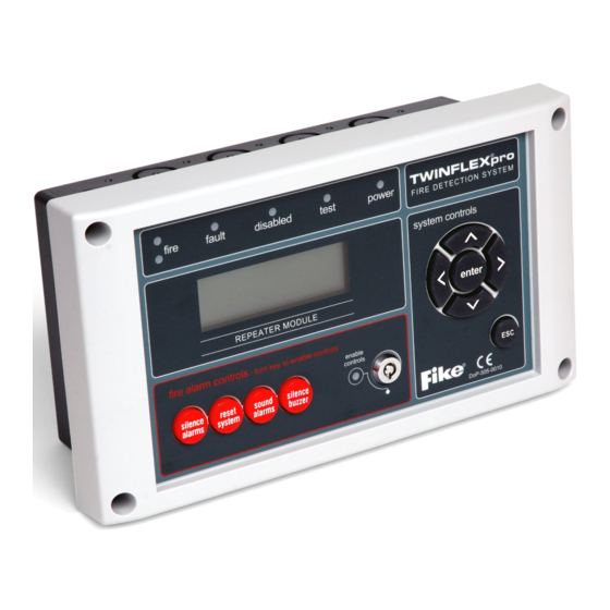
Repeater Panel, Remote Display Unit (RDU)
The TWINFLEX®Pro² repeater panel is smaller than the TWINFLEX®Pro² control panel.
It does not itself connect to or control detection devices. Instead, it connects to a control panel and reports
events which occur on the control panel.
It can also perform system controls over the network (i.e. Silence Alarms, Reset, Sound Alarms & Silence
Buzzer).
A maximum of 8 repeater panels can be connected to a single control panel.
The maximum cable length from the control panel to a repeater is 500 metres. If 8 repeaters are used they
must all be within the maximum 500 metres cable length.
All external connections are made on the back board. The Ext Switches on the back board are not currently
used and are for a future development.
26-1703 Issue 1
Advertisement
Table of Contents

Subscribe to Our Youtube Channel
Related Manuals for Fike Twinflex Pro 2


Summary of Contents for Fike Twinflex Pro 2
- Page 1 T w i n f l e x P r o ² R e p e a t e r P a n e l Q u i c k S t a r t G u i d e Do not attempt to install this equipment until you have fully read and understood the manual which can be found on our website A knowledge of BS5839: Pt 1: 2017: Fire Detection and Alarm Systems for Buildings is essential.
- Page 2 Topology & Cabling All system wiring should be installed to comply with BS 5839: and BS 7671 (wiring regulations) and any other standards relevant to the area or type of installation. A cable complying with BS 5839: Pt 1: Category 1 (cables required to operate for prolonged periods during fire conditions) is required.
- Page 3 Peripheral Bus Connections There are two sets of peripheral bus connections on the panel. These are linked in the panel so either set can be used. A 120Ω Smoothing resistor must also be fitted across NET A & NET B at the panel. On the repeater a 120Ω...
- Page 4 Fike’s policy is one of continual improvement and the right to change a specification at any time without notice is reserved. Whilst every care has been taken to ensure that the contents of this document are correct at time of publication, Fike shall be under no liability whatsoever in respect of such contents.
Need help?
Do you have a question about the Twinflex Pro 2 and is the answer not in the manual?
Questions and answers