Table of Contents

Subscribe to Our Youtube Channel
Related Manuals for Fike TWINFLEX SRP 100-0001


Summary of Contents for Fike TWINFLEX SRP 100-0001
- Page 1 TWINFLEX ® Single Flood Zone Fire Suppression System Control Panel 100-0001 ® (Suitable for TWINFLEX SRP control panels from V01.000) Control Panel Engineering and Commissioning Manual (TO BE RETAINED BY THE COMMISSIONING ENGINEER) 26-1361-02...
- Page 2 Fike’s policy is one of continual improvement and the right to change a specification at any time without notice is reserved. Whilst every care has been taken to ensure that the contents of this document are correct at time of publication, Fike shall be under no liability whatsoever in respect of such contents.
-
Page 3: Table Of Contents
® TWINFLEX SRP Control Panel Engineering and Commissioning Manual Contents GLOSSARY OF TERMS ......................5 INTRODUCTION ........................6 System Design ............................6 Equipment Guarantee ..........................6 Anti-Static Handling Guidelines ......................6 Warning ..............................6 EMC ................................7 ® THE TWINFLEX SRP SYSTEM .................... - Page 4 ® TWINFLEX SRP Control Panel Engineering and Commissioning Manual Hold State / Hold Sound Patterns ....................27 Auto/Manual operation ....................... 28 Extinguishant Flow, Discharge Pressure Input Operation ............28 Power Start Up with batteries only ..................... 28 Control Panel Front ..........................29 LED Indication ............................
-
Page 5: Glossary Of Terms
® TWINFLEX SRP Control Panel Engineering and Commissioning Manual INSTALLATION CHECKLIST ....................72 Stage 1 ..............................72 Stage 2 ..............................72 COMMISSIONING CHECKLIST ................... 73 Step 1 ..............................73 Step 2 ..............................73 Step 3 ..............................73 Step 4 ..............................73 CABLE CONTINUITY &... -
Page 6: Introduction
Failure to do so may result in damage to the equipment and could invalidate the warranty. For technical support please contact your distributor. Do not call the Fike Safety Technology support department unless your distributor has first given their advice and attempted to rectify the issue. -
Page 7: Emc
® TWINFLEX SRP Control Panel Engineering and Commissioning Manual This equipment when installed is subject to the EMC directive 2004/108/EC. It is also subject to UK Statutory Instrument 2006 No. 3418. To maintain EMC compliance, this system must be installed as defined within this manual. Any deviation from this renders the installer liable for any EMC problems that may occur either to the equipment or to any other equipment affected by the installation. - Page 8 ® TWINFLEX SRP Control Panel Engineering and Commissioning Manual ® SRP panels include some features described in EN54-2 as ‘optional functions with The TWINFLEX requirements’. These are:- Output to fire alarm devices EN54-2 Clause 7.8 Output to fire protection equipment, type A EN54-2 Clause 7.10.1 Delays to outputs EN54-2 Clause 7.11.1...
-
Page 9: Control Panel
® TWINFLEX SRP Control Panel Engineering and Commissioning Manual Control Panel Mounting the Control Panel First identify the proposed location for the control panel. Ensure that the control panel will be easily accessible and that account is taken of any subsequent work that may affect access. The control panel should be located at the most likely point of access for the fire services. - Page 10 ® TWINFLEX SRP Control Panel Engineering and Commissioning Manual NOTE: The 14mm flange facilitates flush mounting. To allow installation of the main front moulding, this flange must be flush with the mounting surface and not recessed into it.
-
Page 11: Power Supply Unit
Mode Power Supply located behind the connector board mounting plate. Only the power supply provided in the unit may be used to power the control panel. Both mains termination and location of power supply are shown below. The control panel requires standby batteries. Fike recommends 2 x Yuasa Y Y12-12 or equivalent. UCEL The sealed lead acid batteries should be installed according to the following diagram. -
Page 12: General Assembly
® TWINFLEX SRP Control Panel Engineering and Commissioning Manual Note that batteries are electrically live at all times and great care should be taken to ensure that the terminals are never presented with a short circuit. Care should be taken at all times, especially during transit, installation and normal use. -
Page 13: Topology & Cabling
(at the SCRN terminal provided, not at any earthing point). Do not connect the screen to a device back box other than one supplied by Fike. 4. The cable screen continuity must be maintained at every point of the circuit, using the terminals provided or a suitable connection block. -
Page 14: System Wiring Schematic
® TWINFLEX SRP Control Panel Engineering and Commissioning Manual System Wiring Schematic The four zones can be configured in menu option 9 as follows: Off, Zone not in use. Twinflex, Twinflex detection zone, as shown in the schematic below Conventional, Conventional detection zone Release IRM, Impulse releasing module zone... -
Page 15: Control Panel Connections
® TWINFLEX SRP Control Panel Engineering and Commissioning Manual Control Panel Connections Main Display Board TERMINAL DESCRIPTION Write Protect/Write Enable Switch USB-B connection for pc link Buzzer Link Jumper LCD Contrast... -
Page 16: Releasing Connector Board
® TWINFLEX SRP Control Panel Engineering and Commissioning Manual Releasing Connector Board TERMINAL DESCRIPTION RSI Communication Positive connection for RSI communication Negative connection for RSI communication SCRN Screen connection for RSI communication Positive connection for RSI communication Negative connection for RSI communication SCRN Screen connection for RSI communication MONITORED I/P 1-5... -
Page 17: Ethernet
® TWINFLEX SRP Control Panel Engineering and Commissioning Manual Ethernet This port on the panel is reserved for future use. Write Protect / Write Enable Switch The write protect / write enable switch is a two position switch which is normally set to stop options in the engineer menu from being inadvertently changed. -
Page 18: Rsi Peripheral Bus Connections: A1, B1, Scrn Or A2, B2, Scrn
® TWINFLEX SRP Control Panel Engineering and Commissioning Manual RSI Peripheral Bus Connections: A1, B1, SCRN or A2, B2, SCRN These ports on the panel are for connections to a Remote Status Indicator (RSI) device (Maximum 8 devices). This is an RS-485 connection operating at 57.6 kbps. NOTES An RSI must be setup to be supervised in order to operate with the SRP. -
Page 19: Programmable Inputs 1-5: Mi# +, Mi# -, Scrn
® TWINFLEX SRP Control Panel Engineering and Commissioning Manual Programmable Inputs 1-5: MI# +, MI# -, SCRN ON BOARD PCB FIELD CONNECT IONS MI1 + N/O CONTACT MI1 - Ohms SCRN Ohms SCREEN Activate On Closing Contact ON BOARD PCB FIELD CONNECTIONS MI1 + N/C CONTACT... -
Page 20: Fault Relay: C, N/C, N/O
® TWINFLEX SRP Control Panel Engineering and Commissioning Manual Fault Relay: C, N/C, N/O ON BOARD PCB FIELD CONNECTIONS NORMALLY CLOSED NORMALLY OPEN COMMON The fault relay is derived from a single pole change over ‘volt-free’ relay contact which is not fault monitored. -
Page 21: Monitored Outputs 1 -3: Mo# +, Mo# -, Scrn
® TWINFLEX SRP Control Panel Engineering and Commissioning Manual Monitored Outputs 1 -3: MO# +, MO# -, SCRN Notification Device Connections ON BOARD PCB FIELD CONNECTIONS MO + MO - SCRN SOLENOID SCREEN COIL SUPERVISION ASSEMBLY 17-0136 Releasing Device Connections A Monitored Output can be used to connect either Releasing (solenoid) or Notification devices. - Page 22 ® TWINFLEX SRP Control Panel Engineering and Commissioning Manual Monitored outputs can be configured to the following settings: OUTPUT TYPE Notification Release OUTPUT STATE Release Pre-Release Alarm OUTPUT PATTERN Continuous Slow Fast Temporal User 1-4 SILENCEABLE IMPORTANT NOTE: If the Behaviour of the monitored output is configured and then the Type is changed from Notification to Releasing or vice versa the panel clears out the Behaviour to default setting.
-
Page 23: Device Zones: Z1 - Z4 (Twinflex Devices)
(at the SCRN terminal provided, not at any earthing point). Do not connect the screen to any device back box other than one supplied by Fike. 3. The cable screen continuity must be maintained at every point of the circuit, using the terminals provided or a suitable connection block. -
Page 24: Device Zones: Z1 - Z4 (Conventional Devices)
® TWINFLEX SRP Control Panel Engineering and Commissioning Manual Device Zones: Z1 - Z4 (Conventional Devices) Connecting non-conventional devices to a zone that has been configured for conventional devices can create a fire condition and in some cases cause the panel to go into a release state. EOL –... -
Page 25: Auxiliary Power: Aux Pwr 1-2, +, -, Scrn
® TWINFLEX SRP Control Panel Engineering and Commissioning Manual Auxiliary Power: AUX PWR 1-2, +, -, SCRN ON BOARD PCB FIELD CONNECTIONS SCREEN SCRN 30V DC LOAD An auxiliary nominal 31V DC power supply is available to power ancillary devices requiring up to 30V DC. -
Page 26: Power Supply: Vpsu+, Vpsu-, Earth
® TWINFLEX SRP Control Panel Engineering and Commissioning Manual Power Supply: VPSU+, VPSU-, EARTH ON BOARD PCB FIELD CONNECTIONS EARTH SCRN DC Power from VPSU internal PSU VPSU + DC power from the internal system power supply. 31V DC, 5A rating. Output De-rating Note: Monitored Outputs MO1 to MO3 and AUX PWR 1 and 2 can each supply a maximum of 1A. -
Page 27: General Operation Of Control Panel
® TWINFLEX SRP Control Panel Engineering and Commissioning Manual General Operation of Control Panel Zone Detection & Releasing Operation If one detection zone is activated the panel enters a Fire 1 state. (See EN12094-1:2003 para 4.6) To start the extinguishing release procedure two smoke detection zones must be activated. MCPs or heat detectors configured for Fire 2 when activated will start the extinguishing release and will not require a second zone activation. -
Page 28: Auto/Manual Operation
® TWINFLEX SRP Control Panel Engineering and Commissioning Manual Auto/Manual operation When in Manual mode the following should occur for Twinflex detection If a zone is still enabled and it detects a fire, the panel will log the detection & operate as normal. -
Page 29: Control Panel Front
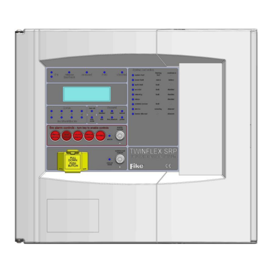
® TWINFLEX SRP Control Panel Engineering and Commissioning Manual Control Panel Front General Indication LEDs System Indication LEDs Control Panel Information System Window Controls Zone Indication LEDs Zone Status LEDs Fire Alarm Controls / Enable Key Switch Extinguishant Auto/Manual General Release Key Switch Status LEDs... - Page 30 ® TWINFLEX SRP Control Panel Engineering and Commissioning Manual The operation of the LED indication on the front of the control panel is described below. The LED indication on the panel can also be confirmed by checking the message displayed in the panel information screen or by accessing the relevant event log from the panel menu.
- Page 31 ® TWINFLEX SRP Control Panel Engineering and Commissioning Manual Flashing A Fault condition exists in a releasing zone or circuit. RELAYS Yellow Continuous A relay has been disabled on the system. EXTERNAL COMMS Yellow Flashing Fault on the external comms, (missing RSI). Flashing The alarm sounders have been activated.
-
Page 32: Fire Alarm Controls
® TWINFLEX SRP Control Panel Engineering and Commissioning Manual Fire Alarm Controls The main Fire Alarm Controls may be enabled by turning the Enable Controls key switch to the Enabled position, or by entering a valid access code The Silence Alarms button will silence any fire alarm sounders that are currently sounding. -
Page 33: Information Window
Information displayed on lines two and TWINFLEX RELEASING three of the default display can be user defined. FIKE (UK) Esc for Menu Press the Esc or ENTER key from this screen to display the main menu. -
Page 34: Enter An Access Code
® TWINFLEX SRP Control Panel Engineering and Commissioning Manual Enter An Access Code To enter an access code from the default screen (shown above), press any number button or the Backspace button. The screen will change (see example below). ENTER ACCESS CODE * - - - PRESS ENTER SW v01.000 key: 4412... -
Page 35: Access Level 1 (Normal)
® TWINFLEX SRP Control Panel Engineering and Commissioning Manual Access Level 1 (Normal): Controls Enabled LED off At Access Level 1 (Normal), the main Fire Alarm Controls are disabled and the following System Menus are all that can be accessed. Fire Alarm Controls will only be accessible if the key switch is turned or the User Level password is entered. - Page 36 ® TWINFLEX SRP Control Panel Engineering and Commissioning Manual 1 View Events 5 All Events The display will show all current events. These may be scrolled FAULT 9/19 through with the LEFT and RIGHT arrow keys. Press the Esc key to 2014/03/22 14:22:02 exit the menu.
-
Page 37: Access Level 2A (User)
® TWINFLEX SRP Control Panel Engineering and Commissioning Manual Access Level 2A (User): Controls Enabled Key or Factory Default Code 8737 Enable Controls LED ON if selected using the enabled controls key switch. Enable Controls LED FLASHING if selected using the user password At Access Level 2A (User), the main Fire Alarm Controls are enabled, “USR”... - Page 38 ® TWINFLEX SRP Control Panel Engineering and Commissioning Manual 1 View Events 3 Fault Events The display will show any current faults. These may be scrolled FAULT 9/19 through with the LEFT and RIGHT arrow keys. Press the Esc key to 2014/03/22 14:22:02 exit the menu.
- Page 39 ® TWINFLEX SRP Control Panel Engineering and Commissioning Manual 2 View Logs 4 Fault Events The Fault Log will display a log of any fault conditions received by the FAULT 853/2695 panel. These may be scrolled through with the LEFT and RIGHT 2014/03/22 14:22:02 arrow keys.
- Page 40 ® TWINFLEX SRP Control Panel Engineering and Commissioning Manual 3 Test Modes 1 Test Ctrls & Disp 4 Keypad The Test Keypad function enables the user to select each button to KEYPAD TEST ensure the correct function is shown on the screen. Press the Esc key “SILENCE ALARMS”...
-
Page 41: Access Level 2B (Supervisor)
® TWINFLEX SRP Control Panel Engineering and Commissioning Manual Access Level 2B (Supervisor): Factory default code 7877 Enable Controls LED flashing At Access Level 2B (Supervisor), the main Fire Alarm Controls are enabled, “SPR” is displayed on the home screen and the following System Controls are accessible: These are described below. - Page 42 ® TWINFLEX SRP Control Panel Engineering and Commissioning Manual 1 View Events 1 Fire Events The display will show any current fire events. These may be scrolled FIRE 1/1 through with the LEFT and RIGHT arrow keys. Press the Esc key to 2014/03/22 14:22:02 exit the menu.
- Page 43 ® TWINFLEX SRP Control Panel Engineering and Commissioning Manual 2 View Logs 1 All Logs The Event Log stores 61184 fire, fault and system events which may FAULT 44/29563 be displayed in a single group or by category. These may be scrolled 2014/03/22 14:22:02 through with the LEFT and RIGHT arrow keys.
- Page 44 ® TWINFLEX SRP Control Panel Engineering and Commissioning Manual Test Ctrls & Disp 3 Test Modes The Test Controls & Display function allows the selection of multiple TESTS (10 seconds): tests. Select Enter to execute the selected test. LCD DISPLAY LEDS BUZZER KEYPAD...
- Page 45 ® TWINFLEX SRP Control Panel Engineering and Commissioning Manual 4 Time And Date 1 Set Time & Date This allows the time and date to be adjusted. Use the LEFT and SET TIME & DATE RIGHT arrow keys to move the cursor between digits and the UP and TIME: 13:10 DOWN arrow keys or the number keys to change values.
-
Page 46: Access Level 3 (Engineer)
® TWINFLEX SRP Control Panel Engineering and Commissioning Manual Access Level 3 (Engineer): Factory default code 3647 Controls Enabled LED flashing At Access Level 3A (Engineer), the main Fire Alarm Controls are enabled, “ENG” is displayed on the home screen and the following System Controls are accessible. To change options contained within the engineer menu, enter Access Level 3B. - Page 47 ® TWINFLEX SRP Control Panel Engineering and Commissioning Manual Available menu options are described below. Note that actual display indications may differ from those shown in the grey boxes below, depending on actual set up.
- Page 48 ® TWINFLEX SRP Control Panel Engineering and Commissioning Manual 1 View Events 1 Fire Events The display will show any current fire events. These may be scrolled FIRE 1/1 through with the LEFT and RIGHT arrow keys. Press the Esc key to 2014/03/22 14:22:02 exit the menu.
- Page 49 ® TWINFLEX SRP Control Panel Engineering and Commissioning Manual 2 View Logs 1 All Logs The Event Log stores 61184 fire, fault and system events which may FAULT 44/29563 be displayed in a single group or by category. These may be scrolled 2014/03/22 14:22:02 through with the LEFT and RIGHT arrow keys.
- Page 50 ® TWINFLEX SRP Control Panel Engineering and Commissioning Manual Test Ctrls & Disp 3 Test Modes The Test Controls & Display function allows the selection of multiple TESTS (10 seconds): tests. Select Enter to execute the selected test. LCD DISPLAY LEDS BUZZER KEYPAD...
- Page 51 ® TWINFLEX SRP Control Panel Engineering and Commissioning Manual 3. Test Modes 2. Test Zones TEST ZONES ZONE: 01 MODE: Test Off ↑/↓ / → /← / Test Off – Stops all test modes. Silent - Allows the selection of one or more detection-zones to operate in a ‘silent one-man walk test mode’. On triggering a device, the device LED operates and the event is recorded into the event log as a test activation, but the sounder does not sound and the control panel does not show an alarm.
- Page 52 ® TWINFLEX SRP Control Panel Engineering and Commissioning Manual 3. Test Modes 5. Test Inputs Allows inputs 1 - 5 to be verified. Indicates status of input. TEST INPUT Blank = input is not configured = switch is not active (see page 18) = switch is active Esc to return = circuit is shorted...
- Page 53 ® TWINFLEX SRP Control Panel Engineering and Commissioning Manual 5 Enable/ Disable 2 Releasing Outputs Enable or Disable Releasing outputs. ENABLE/DISABLE Mode: Enable or Disable (default = enable) ALL RELEASING OUTS? 1. Enable Disable → /← / Enter 5 Enable/ Disable 3 All Sounders This function allows the global disablement or enablement of all the ENABLE/DISABLE...
- Page 54 ® TWINFLEX SRP Control Panel Engineering and Commissioning Manual 6. Diagnostics Screen 4 → The values shown are for example purposes only. ZONE1 (I) 4mA Pressing the Enter Key will toggle between ADC Values and ZONE1 (I) 4mA calculated values. ZONE1 (I) 4mA The RIGHT arrow key will take you to the next screen.
- Page 55 ® TWINFLEX SRP Control Panel Engineering and Commissioning Manual 2. Manual Release 8. Release Config Type Select system manual release type: Enter Countdown or Release ON MANUAL RELEASE, Instantly. This will determine operation when the manual release input THE SYSTEM WILL: has been activated on the control panel.
- Page 56 ® TWINFLEX SRP Control Panel Engineering and Commissioning Manual 10. Detectors Sets up the operation for a heat alarm when Twinflex detectors are DETECTORS used. A Twinflex heat detector activation can either put the panel into HEAT DETECTOR WILL Fire 1 (Alarm) or Fire 2 (Pre-release) states. SET STATE: Fire 2 The default setting is Fire 1 Alarm.
- Page 57 ® TWINFLEX SRP Control Panel Engineering and Commissioning Manual 11. Panel I/O 2. MONITORED OUTPUTS This allows the selection of subscreens that will allow setting the Type OUTPUT OPTIONS and Behaviour of the outputs. 1 Type 2 Behaviour 11. Panel I/O 1 Type screen This will allow the engineer to view or change the operation of OUTPUT: 01...
- Page 58 ® TWINFLEX SRP Control Panel Engineering and Commissioning Manual 11. Panel I/O 3. Prog Relays This will allow the engineer to view or change the operation of RELAY: 01 programmable relay 01 - 04. The NAME can be up to 14 characters STATE: NO STATE long.
- Page 59 ® TWINFLEX SRP Control Panel Engineering and Commissioning Manual 12. Panel Details This will allow the engineer to select the Access Codes or Panel ID submenus. PANEL DETAILS 1 SET ACCESS CODES 2 PANEL ID 12. Panel Details 1. Set Access Codes This will allow the engineer to select which access code will be modified.
- Page 60 ® TWINFLEX SRP Control Panel Engineering and Commissioning Manual 12. Panel Details 2. Panel ID 1 Description line 2 This will allow the engineer to view or change line 2 of the panel PANEL DESCRIPTION description. Use the UP and DOWN keys to change the character and LINE 2: LEFT or RIGHT to move the cursor.
-
Page 61: Installation And Commissioning
® TWINFLEX SRP Control Panel Engineering and Commissioning Manual Installation and Commissioning Installation 1 Stage The installer must install the system wiring in the form of 2-core radial circuits. The cabling should be 2 core 1.5mm , screened and fire resistant, of an MICC or FP200 equivalent type. 4 core cable as a zone in and zone out must not be used, due to the possibility of data corruption. -
Page 62: Commissioning
® TWINFLEX SRP Control Panel Engineering and Commissioning Manual Commissioning ® Commissioning the TWINFLEX SRP system involves programming and testing the system for correct operation. It is essential that every device is tested in every mode of operation, and that all programmed actions are observed for correct operation. -
Page 63: Fault Finding
® TWINFLEX SRP Control Panel Engineering and Commissioning Manual Fault Finding Summary of Faults Intermittent Zone Fault Tighten the unused ‘zone screw terminals’ at the EOL device and check all connections on the zone. Too many sounders on a zone. Remove some or adjust sound levels down. EOL resistor, capacitor or third party EOL device has been fitted. -
Page 64: False Alarms
® TWINFLEX SRP Control Panel Engineering and Commissioning Manual False Alarms Dirty or contaminated optical chambers. Replace with a new optical chamber or device. Incorrectly set smoke detector (smoke is not suitable for kitchens, bathrooms, boiler rooms etc., however, SM3 may be suitable outside a bathroom or kitchen but the individual situation needs to be looked at very carefully). -
Page 65: Finding Zone Faults
® TWINFLEX SRP Control Panel Engineering and Commissioning Manual Finding Zone Faults ® A fault on a zone of the TWINFLEX SRP system may be found as follows: In order to prove whether the fault is control panel based or in the field (including the field wiring), swap the wires from the zone in fault with those in a clear zone (active but no fault) at the control panel. -
Page 66: Advanced Connections
® TWINFLEX SRP Control Panel Engineering and Commissioning Manual Advanced Connections Magnetic Door Hold Units If magnetic door hold devices are required, it is recommended that they are connected to monitored outputs MO1, MO2 or MO3 as shown in the upper right diagram. This is suitable if it is convenient to cable to the control panel. -
Page 67: Technical Data
® TWINFLEX SRP Control Panel Engineering and Commissioning Manual Technical Data Control Panel Specification Dimensions (mm) 375 x 332 x 127 Weight (excluding batteries) 2.25 kg Construction 5VB rated ABS and Metal back box IP Rating IP 30 Cable Entry 19 x 20mm knockouts Cable type 2 core 1.5mm... -
Page 68: Control Panel Fuses And Protection
® TWINFLEX SRP Control Panel Engineering and Commissioning Manual Control Panel Fuses and Protection Zone output 300 mA trip polyfuse Monitored output 1A trip polyfuse Auxiliary 24V DC supplies 2A Fast Blow Fuse Mains T5A Time Delayed 20mm Ceramic (in mains terminal block) Battery Charger 1.2 A current limiter Battery (reverse polarity) -
Page 69: Factory Default Settings & Profiles
® TWINFLEX SRP Control Panel Engineering and Commissioning Manual Factory Default Settings & Profiles, Profile 1 Profile 2 Profile 3 Profile 4 Config Name Active Profile Impulse/TF Solenoid/TF Impulse/Conv Solenoid/Conv Release Type: hold type hold pattern manual release type instant release instant release instant release instant release... - Page 70 TWINFLEX TWINFLEX TWINFLEX TWINFLEX TWINFLEX main display line 2 RELEASING RELEASING RELEASING RELEASING RELEASING main display line 3 FIKE (UK) FIKE (UK) FIKE (UK) FIKE (UK) FIKE (UK) aux1 Power Constant Power Constant Power Constant Power Constant Power Constant aux2...
-
Page 71: Battery Calculations
® TWINFLEX SRP Control Panel Engineering and Commissioning Manual Battery Calculations Where: IS = Standby Current, IA = Alarm Current, MP = Multipoint Detector Note: An Excel spreadsheet (document no. 26-1389) is also available to automatically work out both standby battery calculations and zone loading calculations based on the quantities entered. -
Page 72: Installation Checklist
® TWINFLEX SRP Control Panel Engineering and Commissioning Manual Installation Checklist Use the following checklist to ensure that your work is correct and that the commissioning engineer has the necessary information to complete the commissioning of the system If you require a commissioning visit, the engineer will require this sheet, along with ‘Zone Continuity and Insulation Test Results’... -
Page 73: Commissioning Checklist
® TWINFLEX SRP Control Panel Engineering and Commissioning Manual Commissioning Checklist The following checklist may be used to ensure that all steps are taken. This is not a BS5839 certificate and serves as a reminder only and may need additional items added to suit your working practices. Step 1 Description Commissioning... -
Page 74: Cable Continuity & Insulation Test Results
® TWINFLEX SRP Control Panel Engineering and Commissioning Manual Cable Continuity & Insulation Test Results After installation of the cable, and termination into all the relevant back-boxes, install a wire link between the zone +ve and –ve connections at the last device in order to be able to take cable continuity readings, removing it to take insulation readings. -
Page 75: Fire Alarm System Notice
® TWINFLEX SRP Control Panel Engineering and Commissioning Manual FIRE ALARM SYSTEM NOTICE To Enable the Fire Alarm Control Panel Keys You may gain access to the Fire Alarm Controls by inserting the key turning ¼ turn or by entering any valid access code. The ‘Controls Enabled’... -
Page 76: Fire Alarm User Notice
® TWINFLEX SRP Control Panel Engineering and Commissioning Manual FIRE ALARM USER NOTICE Note Please read and understand the following information in order to make the most use of the system Action Required If you think that you may have accidentally set off the fire alarms, then check the following: If the fire alarm within your area only is sounding, then check your own area for the cause of the alarm. -
Page 77: Engineers Notes
® TWINFLEX SRP Control Panel Engineering and Commissioning Manual Engineers Notes... -
Page 78: Technical Support
Manual only mode support on this product. Triggering of equipment within the system Triggering of equipment outside the system Do not call the Fike Safety Technology technical support department unless your Control of extended discharge distributor has first given their advice and attempted to rectify the issue.
Need help?
Do you have a question about the TWINFLEX SRP 100-0001 and is the answer not in the manual?
Questions and answers