Table of Contents
Advertisement
Industrial Automation Headquarters
Delta Electronics, Inc.
Taoyuan Technology Center
No.18, Xinglong Rd., Taoyuan City,
Taoyuan County 33068, Taiwan
TEL: 886-3-362-6301 / FAX: 886-3-371-6301
Asia
Delta Electronics (Jiangsu) Ltd.
Wujiang Plant 3
1688 Jiangxing East Road,
Wujiang Economic Development Zone
Wujiang City, Jiang Su Province, P.R.C. 215200
TEL: 86-512-6340-3008 / FAX: 86-769-6340-7290
Delta Greentech (China) Co., Ltd.
238 Min-Xia Road, Pudong District,
ShangHai, P.R.C. 201209
TEL: 86-21-58635678 / FAX: 86-21-58630003
Delta Electronics (Japan), Inc.
Tokyo Office
2-1-14 Minato-ku Shibadaimon,
Tokyo 105-0012, Japan
TEL: 81-3-5733-1111 / FAX: 81-3-5733-1211
Delta Electronics (Korea), Inc.
1511, Byucksan Digital Valley 6-cha, Gasan-dong,
Geumcheon-gu, Seoul, Korea, 153-704
TEL: 82-2-515-5303 / FAX: 82-2-515-5302
Delta Electronics Int'l (S) Pte Ltd.
4 Kaki Bukit Ave 1, #05-05, Singapore 417939
TEL: 65-6747-5155 / FAX: 65-6744-9228
Delta Electronics (India) Pvt. Ltd.
Plot No 43 Sector 35, HSIIDC
Gurgaon, PIN 122001, Haryana, India
TEL : 91-124-4874900 / FAX : 91-124-4874945
Americas
Delta Products Corporation (USA)
Raleigh Office
P.O. Box 12173,5101 Davis Drive,
Research Triangle Park, NC 27709, U.S.A.
TEL: 1-919-767-3800 / FAX: 1-919-767-8080
Delta Greentech (Brasil) S.A.
Sao Paulo Office
Rua Itapeva, 26 - 3° andar Edificio Itapeva One-Bela Vista
01332-000-São Paulo-SP-Brazil
TEL: 55 11 3568-3855 / FAX: 55 11 3568-3865
Europe
Deltronics (The Netherlands) B.V.
Eindhoven Office
De Witbogt 20, 5652 AG Eindhoven, The Netherlands
TEL: 31-40-2592850 / FAX: 31-40-2592851
DVP-0099720-01
*We reserve the right to change the information in this manual without prior notice.
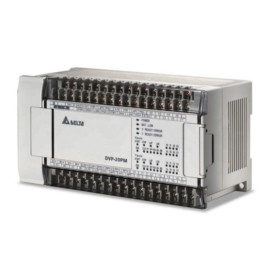
DVP-20PM
Application Manual
(Programming)
2014-02-12
www.deltaww.com
Advertisement
Chapters
Table of Contents

Related Manuals for Delta DVP-20PM


Summary of Contents for Delta DVP-20PM
- Page 1 1511, Byucksan Digital Valley 6-cha, Gasan-dong, DVP-20PM Geumcheon-gu, Seoul, Korea, 153-704 TEL: 82-2-515-5303 / FAX: 82-2-515-5302 Delta Electronics Int’l (S) Pte Ltd. Application Manual 4 Kaki Bukit Ave 1, #05-05, Singapore 417939 TEL: 65-6747-5155 / FAX: 65-6744-9228 Delta Electronics (India) Pvt. Ltd.
-
Page 2: Table Of Contents
2.1.2 Electrical Specifications for Input Terminals/Output Terminals...... 2-1 2.1.3 Dimensions....................2-4 Wiring ........................2-6 2.2.1 Installation of a DVP-20PM Series Motion Controller in a Control Box..2-7 2.2.2 Wiring Power Input ..................2-7 2.2.3 Safety Wiring ....................2-8 2.2.4 Wiring Input/Output Terminals ..............2-8 2.2.5... - Page 3 Definitions of Input Pins/Output Pins ............5-146 5.8.2 Timing Diagram for Input/Output Pins ............5-148 5.8.3 Introducing the Use of PMSoft..............5-148 Delta-defined Parameter Table ................ 5-150 5.10 Uniaxial Motion Control Function Blocks ............5-152 5.10.1 Absolute Single-speed Motion..............5-152 5.10.2...
- Page 4 5.10.3 Absolute Two-speed Motion ..............5-160 5.10.4 Relative Two-speed Motion ..............5-163 5.10.5 Inserting Single-speed Motion ..............5-166 5.10.6 Inserting Two-speed Motion ..............5-170 5.10.7 JOG Motion ....................5-174 5.10.8 Manual Pulse Generator Mode..............5-177 5.10.9 Electronic Gear Motion................5-179 5.10.10 Returning Home ..................
- Page 5 Descriptions of Motion Instructions..............6-7 Descriptions of O Pointers/M-code Instructions..........6-40 Descriptions of G-code Instructions..............6-45 Chapter 7 Using a DVP-20PM Series Motion Controller as a Slave Access between DVP-EH2, DVP20PM (as a Master) and DVP-20PM (as a Slave) ..........................7-1 7.1.1 Structure....................... 7-1 7.1.2...
- Page 6 9.2.3.2 Starting/Stopping a Noncyclic Electronic Cam........9-13 Registers for Electronic Cam Motion ..............9-15 Creating Electronic Cam Data ................9-19 9.4.1 Creating a Cam Chart in PMSoft ..............9-20 9.4.1.1 Function Relating the Position of a Master Axis to the Position of a Slave Axis .....................9-20 9.4.1.2 Measuring the Relation between the Position of a Master Axis and the...
- Page 7 11.4 Parameters for Control Registers ..............11-2 11.5 Descriptions of Control Registers ..............11-4 11.6 Setting a DVP-FPMC Mode................11-19 11.7 Ethernet Mode of DVP-FPMC ................. 11-21 11.7.1 Communication between DVP-FPMC and an HMI........11-22 11.7.2 Communication between DVP-FPMC and PMSoft........11-24 11.8 LED Indicators and Troubleshooting ...............
- Page 8 v i i...
-
Page 9: Chapter 1 Program Framework Of A Dvp-Pm Series Motion Controller
Program Framework of a DVP-PM Series Motion Controller Delta DVP-PM series motion controllers can put axes in particular positions at high-speeds, create linear interpolations, and circular interpolations. They can execute basic instructions, applied instructions, motion instructions, and G-codes. Different DVP-PM series motion controllers support different program frameworks and functions. -
Page 10: Manual Function Of O100
P subroutines can be arranged in any order. 1.1.1 Manual Function of O100 Users can set manual motion modes by means of special registers in O100. (Please refer to section 3.12 for more information.) DVP-20PM Application Manual... -
Page 11: Structure Of Ox Motion Subroutines
D1846 to 0, or to set M1074 to OFF, and to stop the execution of Ox motion subroutines. If an error occurs when an Ox motion subroutine is compiled or when an Ox motion subroutine is DVP-20PM Application Manual... -
Page 12: Structure Of P Subroutines
P subroutine will be executed. After the ending instruction SRET in the P subroutine is executed, the execution of the P subroutine will stop, and the lines under the instruction which calls the P subroutine will be executed. DVP-20PM Application Manual... - Page 13 Ending instruction SRET (If a P subroutine is a ladder diagram in PMSoft, the ending Disabling a P instruction SRET will be set automatically, and users do not have to write the ending subroutine instruction SRET.) DVP-20PM Application Manual...
-
Page 14: Using O100, Ox Motion Subroutines, And P Subroutines
SR ET . . C al li ng P2 Sub rou ti ne . . . . Moti on subroutine . C al li ng Ox3 . Ox 3 . M1 02 . . . SR ET DVP-20PM Application Manual... - Page 15 1. One Ox motion subroutine is executed at a time. If Ox0 is executed, Ox3 can not be executed. If Ox3 is executed, Ox0 can not be executed. 2. After O100 or a P subroutine enables an Ox motion subroutine, the next line will be executed, and the execution of the Ox motion subroutine will be ignored. DVP-20PM Application Manual...
- Page 16 256 subroutines 100 motion subroutines Number 1 main program They can be used They can be used according to users’ needs. according to users’ needs. DVP-20PM Application Manual...
-
Page 17: Chapter 2 Hardware Specifications And Wiring
The diameter of the ground should not be less than the diameters of the cables connected Ground to the terminals L and N. (If several DVP-20PM series motion controllers are used, please use single-point ground.) Operation:0°C~55°C (Temperature), 5~95% (Humidity), pollution degree 2 Operation/Storage Storage: -25°C ~70°C (Temperature), 5~95% (Humidity) - Page 18 CLR signals (for clearing the present positions of CLR0+, CLR0-, servo drives which are stored in registers in the 10 ms 20 mA CLR1+, and CLR1- servo drives) CLR signal (for the Z-axis) 10 ms 30 mA DVP-20PM Application Manual...
- Page 19 A/B: B phase Y3~Y7 General output terminals 200 kHz 40 mA Digital input terminals: DVP-20PM series motion controller Item 24 V DC common terminal Remark Specifications Low speed High speed of 200 kHz A current flows into the terminal S/S (sinking), or a...
-
Page 20: Dimensions
Hardware Specifications and Wiring #2: Life cycle curve 120VAC Resistive 3000 30VDC Inductive(t=7ms) 2000 240VAC Inductive(cos ψ 0.4) 1000 120VAC Inductive(cos =0.4) ψ 30VDC Inductive (t=40ms) 100~200VDC Inductive (t=7~40ms) Contact Current(A) 0.7 1 2.1.3 Dimensions 82.2 (Unit: mm) DVP-20PM Application Manual... - Page 21 Hardware Specifications and Wiring Profile DVP-20PM series motion controller ○ Communication port cover ○ Input/Output terminal cover ○ Function card cover ○ Input LED indicators ○ Output LED indicators Input/Output terminal ○ numbers ○ Input/Output terminals ○ Connector cover ○...
-
Page 22: Wiring
RP2- 2.2 Wiring A DVP-20PM series motion controller is an OPEN-TYPE device. It should be installed in a control cabinet free of airborne dust, humidity, electric shock and vibration. To prevent non-maintenance staff from operating a DVP-10PM series motion controller, or to prevent an accident from damaging a DVP-10PM series motion controller, the control cabinet in which a DVP-10PM series motion controller is installed should be equipped with a safeguard. -
Page 23: Installation Of A Dvp-20Pm Series Motion Controller In A Control Box
2.2.2 Wiring Power Input The power input of a DVP-20PM series motion controller is AC input. Users have to pay attention to the following points. The voltage of AC power input is in the range of 100 V AC to 240 V AC. A live wire and a neutral wire are connected to L and N. -
Page 24: Safety Wiring
Direct-current power output: 24 V DC, 500 mA 2.2.4 Wiring Input/Output Terminals 1. The power input of a DVP-20PM series motion controller is DC power input. Sinking and sourcing are current driving capabilities of a circuit. They are defined as follows. Sinking:... - Page 25 Equivalent circuit of an input circuit SINK +24V 24VDC Wiring +24V S/S X0 X1 X2 Sink Type Sourcing: DC power input Sourcing Souring: The current flows from the common terminal S/S. Equivalent circuit of an input circuit SOURCE +24V 24VDC DVP-20PM Application Manual...
- Page 26 The direct-current signals ranging in voltage from 5 V to 24 V can pass through the high-speed input terminals A0~A1 and B0~B1 on a DVP-20PM series motion controller. The frequency of input signals can be up to 200 kHz. These high-speed input terminals are connected to a differential (two-wire) line driver.
- Page 27 Mutually exclusive output: Y4 controls the clockwise rotation of a motor, and Y5 controls the counterclockwise rotation of a motor. The interlock circuit which is formed, and the program in the DVP-20PM series motion controller ensure that there will be protective measures if an abnormal condition occurs.
- Page 28 Th e p owe r o f the lo ad is l ar ge an d th e l oa d i s tur ne d O N/OFF fr eq ue ntl y. V DC ZD D D: 1 N40 01 di od e DVP-20PM Application Manual 2-12...
- Page 29 5. Wiring differential output terminals Wiring differential output terminals on a DVP-20PM series motion controller and an ASDA-A series AC servo drive/ASDA-A+ series AC servo drive/ASDA-A2 series AC servo drive Differ ential output ter minals on a...
-
Page 30: Wiring A Dvp-20Pm Series Motion Controller And An Inferior Servo Drive
Hardware Specifications and Wiring 2.2.5 Wiring a DVP-20PM Series Motion Controller and an Inferior Servo Drive Wiring a DVP-20PM series motion controller and a Delta ASDA-A series AC servo drive: Delta se rvo drive A SDA -A se ri es... - Page 31 Hardware Specifications and Wiring Wiring a DVP-20PM series motion controller and a Panasonic CN5 series servo drive: Pa nasonic se rvo drive CN5 series S TART0 2 4V S TO P0 L SP 0 FP 0 + P ULS 1...
- Page 32 Hardware Specifications and Wiring Wiring a DVP-20PM series motion controller and a Yaskawa servo drive: Yaskawa servo drive Yaska wa se ri es S TART0 2 4V S TO P0 L SP 0 P LS FP 0 + L SN0...
- Page 33 Hardware Specifications and Wiring Wiring a DVP-20PM series motion controller and a Mitsubishi MJR2 series servo drive: Mitsubishi servo drive Mitsubishi MJR2 ser ie s S TART0 2 4V S TO P0 L SP 0 FP 0 + L SN0...
- Page 34 Hardware Specifications and Wiring Wiring a DVP-20PM series motion controller and a Fuji servo drive: DVP-20PM Application Manual 2-18...
-
Page 35: Communication Ports
2.3.1 COM1 (RS-232 Port) 1. COM1 is an RS-232 port. Users can upload the program in a DVP-20PM series motion controller through COM1, and download a program to DVP-20PM series motion controller through COM1. The communication protocols that COM1 supports are Modbus ASCII and Modbus RTU, and the transmission rate supported is in the range of 9,600 bps to 115,200 bps. -
Page 36: Com2 (Rs-485 Port)
COM2 can function as a master station or a slave station. If it functions as a master station, it can be connected to a Delta PLC, or an inferior drive such as a Delta servo drive, a Delta AC motor drive, or a temperature controller, and read/write data. -
Page 37: Chapter 3 Devices
I/O module by means of the instruction TO. If the data read or written is 32-bit data, two control registers will be used. If a DVP-20PM series motion controller is used as an I/O module, a master can read the data in CR0~CR199 in the Slave mode DVP-20PM series motion controller or write data into CR0~CR199 in the DVP-20PM series motion controller. - Page 38 M00~M01, M03~M101, and M103~M65535: The execution M-code of a program pauses. (WAIT) (Users can use them freely.) O100 (main program in a DVP-20PM series motion controller/subtask program): M102 (The execution of a program stops. (END)) G0 (rapid positioning), G1 (linear interpolation), G2 (circular...
- Page 39 Start: D1202 (K-1) *2; End: D1203 ( K-1) *2 16-bit up counters 32-bit up/down counters C200, C204, and C0~C99 C100~C199 C220~C255 C208~C219 Counter Non-latching Latching Non-latching Latching Start: D1204 (K100) Start: D1206 (K220) End: D1205 (K199) End: D1207 (K255) DVP-20PM Application Manual...
-
Page 40: Values, Constants, And Floating-Point Numbers
They can not be changed. End: D1211 (K9999) *3 *1: If the value in D1200 is 0, and the value in D1201 is 4095, the DVP-20PM series motion controller used will automatically skip M1000~M2999, and M0~M999 and M3000~M4095 will be changed to latching devices. - Page 41 A hexadecimal number can be used as an operand in an applied instruction, e.g. MOV H1A2B D0 (H indicates that the value following it is a constant.). Constant (K): A decimal number in a DVP-20PM series motion controller is generally preceded by K. For example, K100 represents the decimal number 100.
-
Page 42: External Input Devices And External Output Devices
Functions of input devices: After X devices in a DVP-20PM series motion controller are connected to an input device, the input signals sent to the DVP-20PM series motion controller will be read. There is no limitation on the number of times the Form A contact/the Form B contact of an X device can be used in a program. The state of an X device varies with the state of the input device to which the X device is connected. - Page 43 , that is, the state of X10 determines the state of Y0. Y0 is us ed twic e. The procedure for processing the program in a DVP-20PM series motion controller is described below. Regenerating an input signal: 1. Before a DVP-20PM series motion...
-
Page 44: Auxiliary Relays
M devices. There are three types of auxiliary relays. 1. General auxiliary relay: If a power cut occurs when a DVP-20PM series motion controller runs, the general auxiliary relays in the DVP-20PM series motion controller will be reset to OFF. -
Page 45: Counters
If the present value After the scan of a After the scan of a program is complete, the matches the setting Actions of contacts program is complete, contacts will act. value, the contact will the contacts will act. be ON. DVP-20PM Application Manual... - Page 46 2. If a power cut occurs when a general counter in a DVP-20PM series motion controller counts, the present value of the counter will be cleared. If a power cut occurs when a latching counter counts, the present value of the counter and the state of the contact of the counter will be retained, and the latching counter will not continue counting until power is restored.
- Page 47 X11 is turned from OFF to ON. In crea sing Decreas ing In crea sing X1 0 X1 2 C208 cou nts. Presen t value The o utpu t conta ct is ON. Y0 ,C208 Cont ac t DVP-20PM Application Manual 3-11...
- Page 48 Devices 32-bit high-speed counter: DVP-20PM series motion controller (C200 and C204) 1. The setting value of a 32-bit high-speed counter must be in the range of K-2,147,483,648 to K2,147,483,647. 2. Mode of counting: Mode of counting External Resetting Counter...
-
Page 49: Registers
A setting value can be a positive value, or a negative value. 5. If a power cut occurs when a general counter in a DVP-20PM series motion controller counts, the present value of the counter will be cleared. If a power cut occurs when a latching counter counts, the present value of the counter and the state of the contact of the counter will be retained, and the latching counter will not continue counting until power is restored. -
Page 50: Index Registers
(X/Y/M/S devices). There are 8 V devices (V0~V7), and 8 Z devices (Z0~Z7) in a DVP-20PM series motion controller. ※Constants and some instructions do not support the use of index registers. Please refer to section 5.4 for more information about using index registers to modify operands. - Page 51 “-” indicates that the state of a special auxiliary relay is unchanged, or the value in a special data register is unchanged. “#” indicates that a special auxiliary relay or a special data register in a DVP-20PM series motion controller is set according to the state of the DVP-20PM series motion controller. The users can read a setting value, and refer to the manual for more information.
- Page 52 C213: Selecting a mode of counting (On: Counting ○ ○ M1213 down) C214: Selecting a mode of counting (On: Counting ○ ○ M1214 down) C215: Selecting a mode of counting (On: Counting ○ ○ M1215 down) DVP-20PM Application Manual 3-16...
- Page 53 C243: Selecting a mode of counting (On: Counting ○ ○ M1243 down) C244: Selecting a mode of counting (On: Counting ○ ○ M1244 down) C245: Selecting a mode of counting (On: Counting ○ ○ M1245 down) DVP-20PM Application Manual 3-17...
- Page 54 Ox motion subroutine is executed.) If M02 in an Ox motion subroutine is executed, ○ ○ M1796 M1796 will be ON. (M1796 is reset to OFF at the time when the Ox motion subroutine is executed.) DVP-20PM Application Manual 3-18...
- Page 55 The Z-axis stops at the angle specified. 3-36 ╳ ○ M2032 The Z-axis is ready. 3-36 Z-axis motion error flag (It is reset at the time when ╳ ○ M2033* 3-37 the Z-axis operates.) Additional remark: 20D=DVP20PM00D; 20M=DVP20PM00M DVP-20PM Application Manual 3-19...
- Page 56 Present value of CH0 in the function card 2AD ○ ○ D1057 Present value of CH1 in the function card 2AD Modbus communication data is processed. A DVP-20PM series motion controller has an RS-485 communication instruction. After a D1070 receptor receives the command sent by an ↓ ○...
- Page 57 STOP Error code that a slave station sends by means of Modbus when the RS-485 port on the ○ ○ D1130 DVP-20PM series motion controller functions as a master station Number of right-side modules (8 right-side ○ ○ D1140* 3-35 modules at most) ○...
- Page 58 Number of pulses it takes for the motor of the D1818 X-axis to rotate once (low word) ○ ○ 2000 Number of pulses it takes for the motor of the D1819 X-axis to rotate once (high word) DVP-20PM Application Manual 3-22...
- Page 59 Target position of the X-axis (P (II)) (low word) D1842 ○ ○ Upper limit for a synchronization zone (low word) ○ ○ Target position of the X-axis (P (II)) (high word) D1843 ○ ○ Upper limit for a synchronization zone (high word) DVP-20PM Application Manual 3-23...
- Page 60 (low word) ○ ○ Electrical zero of the X-axis (high word) Number of pulses for switching the source of the D1867 ○ ○ master axis of the noncyclic electronic cam (high word) DVP-20PM Application Manual 3-24...
- Page 61 JOG speed (V ) at which the Y-axis rotates D1907 (high word) Speed (V ) at which the Y-axis returns home D1908 (low word) ○ ○ Speed (V ) at which the Y-axis returns home D1909 (high word) DVP-20PM Application Manual 3-25...
- Page 62 Y-axis (high word) Response speed of the manual pulse generator ○ ○ D1944 for the Y-axis D1946 Electrical zero of the Y-axis (low word) ○ ○ D1947 Electrical zero of the Y-axis (high word) DVP-20PM Application Manual 3-26...
- Page 63 Speed (V ) to which the speed of the Z-axis D1991 decreases when the Z-axis returns home (high word) ╳ ○ D1992 Number of PG pulses for the Z-axis ╳ ○ D1993 Supplementary pulses for the Z-axis DVP-20PM Application Manual 3-27...
- Page 64 Electrical zero of the Z-axis (high word) Step address at which an Oz error occurs (The ╳ ○ D2029 register is not available presently, and is reserved.) Enabling the PID closed-loop control of the ╳ ○ D2037 Z-axis DVP-20PM Application Manual 3-28...
- Page 65 Maximum cumulative error for the PID ╳ ○ D2048 closed-loop control of the Z-axis (low word) Maximum cumulative error for the PID ╳ ○ D2049 closed-loop control of the Z-axis (high word) Additional remark: 20D=DVP20PM00D; 20M=DVP20PM00M DVP-20PM Application Manual 3-29...
-
Page 66: Functions Of Special Auxiliary Relays And Special Data Registers
M1002: A positive-going pulse is generated at the time when the DVP-20PM series motion controller runs. The width of the pulse is equal to the scan cycle. If users want to initialize the DVP-20PM series motion controller, they can use the contact. - Page 67 D1020. The value in D1020 must be in the range of 0 to 20. (Unit: ms) I nput f ilter If the DVP-20PM series motion controller is turned form OFF to ON, the value in S D1020 will automatically become 10.
- Page 68 Undefined Example 1: Modifying the communication format of COM2 If users want to modify the communication format of COM2 on a DVP-20PM series motion controller, they have to add the program shown below to the top of the program in the DVP-20PM series motion controller. After the STOP/RUN switch on the DVP-20PM series motion controller is turned from the STOP position to the RUN position, the state of M1120 will be detected during the first scan cycle.
- Page 69 Devices Notes: 1. If COM2 on a DVP-20PM series motion controller is used as a slave station, no communication instruction can exist in the program in the DVP-20PM series motion controller. 2. If the STOP/RUN switch on a DVP-20PM series motion controller is turned...
- Page 70 D1120 M1120 M1143 If an RS-485 port on a DVP-20PM series motion controller functions as a slave station, users can set a communication timeout. The value in D1038 is in the range of 0 to Co mmunica tion 3,000 (0 to 30 seconds). The unit used is 10 milliseconds. If the value in D1038 is not timeout in the range of 0 to 3,000, the value in D1038 will become 0.
- Page 71 Please refer to section 3.1 for more information. D1200~D1211 If M1304 in a DVP-20PM series motion controller is ON, the X devices (X0~X17) in the DVP-20PM series motion controller can be turned ON/OFF by means of PMSoft. Turning the X...
- Page 72 90 degrees, there will be the states shown below. Stop position of the JOG Starting position Final stop position motion Zero degrees 4000 pulses 5000 pulses (90 degrees) Random angle 63500 pulses 65000 pulses (90 degrees) DVP-20PM Application Manual 3-36...
- Page 73 Y-axis moves will be at right angles. If D1796 is set, the path along which the X-axis moves and the path along which the Y-axis moves will form a smooth curve. G01 X100 F1000; (Block A) Y100; (Block B) DVP-20PM Application Manual 3-37...
- Page 74 D1800 is OFF, the input terminal corresponding to the bit does not receive a s tat es of the signal. in put ter min als State of an input terminal of the State of an input terminal of the Bit# Bit# X-axis Y-axis D1800 STOP STOP START START DVP-20PM Application Manual 3-38...
- Page 75 D1802, and the step address at which the error occurs will O1 00 er ror be stored in D1803. Please refer to appendix A in chapter 15 for more information about error codes. M1953, D1802, and D1803 DVP-20PM Application Manual 3-39...
- Page 76 Bit 11=0: When the motor rotates clockwise, the value indicating the present command position of the axis increases. Bit 11=1: When the motor rotates clockwise, the value indicating the present command position of the axis decreases. Bit 12=0: Absolute coordinates Bit 12=1: Relative coordinates DVP-20PM Application Manual 3-40...
- Page 77 (The setting of bit 13 is applicable to the insertion of single-speed motion, and the insertion of two-speed motion.) Bit 14=0: Trapezoid curve Bit 14=1: S curve Only DVP-20PM series motion controllers support this function. Setting the D1832: Setting the number of times noncyclic electronic cam motion is repeated noncy clic...
- Page 78 Input terminals on DVP20PM00D for manual pulse generators: X-axis (A0+/A0-, B0+/B0-); Y-axis (A1+/A1-, B1+/B1-) Input terminals on DVP20PM00M for manual pulse generators: X-axis (A0+/A0-, B0+/B0-); Y-axis and Z-axis (A1+/A1-, B1+/B1-) *1: Only the Y-axis supports this function. (D1926) *2: Only the X-axis supports this function. (D1846) DVP-20PM Application Manual 3-42...
- Page 79 Limitation on the present position of the slave axis controlled by the manual pulse generator used Mode of stopping the motor used Restoring the DVP-20PM series when the motor used comes into motion controller to the factory contact with a positive limit...
- Page 80 X-axis. The value in (D1889, D1888) indicates the maximum cumulative error for the PID closed-loop control of the X-axis. D1888 and D1889 are used to limit the difference between an input value and an output value. DVP-20PM Application Manual 3-44...
- Page 81 The maximum cumulative error set is used to limit the difference between the source value of the feedback and the present value of the command. If the difference is greater than the maximum cumulative error, there will no output. DVP-20PM Application Manual 3-45...
-
Page 82: Special Data Registers For Motion Axes
3.12 Special Data Registers for Motion Axes The special data registers for the X-axis, the Y-axis, and the Z-axis in a DVP-20PM series motion controller are described below. Please refer to this section for more information about the setting of the special data registers. -
Page 83: Descriptions Of The Special Data Registers Related To Motion
(V ) to which the speed of the axis specified decreases when the axis returns home, speed at which the axis specified rotates (V (I)), and speed at which the axis specified rotates (V (II)) DVP-20PM Application Manual 3-47... - Page 84 Position: µm Speed: Centimeter/minute D1818 (D1898, D1978)=1,000 (pulses/revolution) D1820 (D1900, D1980)=100 (micrometers/revolution) P (I)=10,000 (micrometers) V (I)=6 (centimeters/minute) The number of pulses sent by the DVP-20PM series motion controller and the frequency of pulses are calculated below. Distance Revolution ...
- Page 85 DOG’s signal is generated. After DOG’s signal goes from high to low, the motor will rotate for a specific number of PG0 pulses, and then rotate for a specific number of supplementary pulses, and finally stop whether the its speed is V DVP-20PM Application Manual 3-49...
- Page 86 If the number of PG0 pulses or the number of supplementary pulses is not large, the speed of the motor used will decrease to the speed V after DOG’s signal is generated. After DOG’s signal DVP-20PM Application Manual 3-50...
- Page 87 Bit 11=0: When the motor rotates clockwise, the value indicating the present command position of the axis specified increases. Bit 11=1: When the motor rotates clockwise, the value indicating the present command position of the axis specified decreases. DVP-20PM Application Manual 3-51...
- Page 88 (D1823, D1822) ((D1903, D1902), (D1983, D1982)) is greater than 500K, the frequency of pulses generated will be 500K PPS. If the value in (D1823, D1822) ((D1903, D1902), (D1983, D1982)) is less than 10, the frequency of pulses generated will be 10 PPS. DVP-20PM Application Manual 3-52...
- Page 89 (D1829, D1828) ((D1909, D1908), (D1989, D1988)) is greater than 500K, the frequency of pulses generated will be 500K PPS. If the value in (D1829, D1828) ((D1909, D1908), (D1989, D1988)) is less than 10, the frequency of pulses generated will be 10 PPS. DVP-20PM Application Manual 3-53...
- Page 90 0 and bit 1 in D1816 (D1896, D1976). 2. After the axis specified returns home, the value in (D1835, D1834) ((D1915, D1914), (D1995, D1994)) will be written into (D1849, D1848) ((D1929, D1928), (D2009, D2008)). DVP-20PM Application Manual 3-54...
- Page 91 (D1841, D1840) ((D1921, D1920), (D2001, D2000)) is greater than 500K, the frequency of pulses generated will be 500K PPS. If the value in (D1841, D1840) ((D1921, D1920), (D2001, D2000)) is less than 10, the frequency of pulses generated will be 10 PPS. DVP-20PM Application Manual 3-55...
- Page 92 3. Bit 2 in D1846 (D1926, D2006): The axis specified operates in a JOG+ mode. When bit 2 in D1846 (D1926, D2006), clockwise pulses are generated at the JOG speed set. 4. Bit 3 in D1846 (D1926, D2006): The axis specified operates in a JOG- mode. DVP-20PM Application Manual 3-56...
- Page 93 5. Bit 4 in D1846 (D1926, D2006): A mode of variable motion is activated. After bit 4 in D1846 (D1926, D2006) is set to 1, the DVP-20PM series motion controller will execute variable motion, and it will send pulses by a pulse generator.
- Page 94 P (I) and the V (I) which are set by users, and the DVP-20PM series motion controller sends pulses by a pulse generator. ...
- Page 95 V (I) set. After DOG’s signal goes from BIAS low to high or from high to low, the DVP-20PM series motion controller used will continue sending pulses. The speed of the motion will not decrease from the V (I) set to the V...
- Page 96 Bit 2=0: After the axis specified returns home, the CLR output will send a 130 millisecond signal to the servo drive used, and the present position of the servo drive which is stored in a register in the DVP-20PM Application Manual 3-60...
- Page 97 Bit 10~bit 8=K4 (100): Motion is stopped immediately when there is a transition in B0’s signal from high to low. 8. Bit 15 in D1847 (D1927, D2007): Restoring the DVP-20PM series motion controller to the factory settings ...
- Page 98 The axis specified pauses. The manual pulse generator used generates positive-going pulses. The manual pulse generator used generates negative-going pulses. X-axis Y-axis Z-axis Axis error code D1857 D1937 D2017 [Description] Please refer to chapter 15 for more information. DVP-20PM Application Manual 3-62...
- Page 99 2. If the response speed set is low, the pulses output follows the pulses input by the manual pulse generator used. Setting value Response speed ≧5 4 ms (Initial value) DVP-20PM Application Manual 3-63...
-
Page 100: Introduction Of Modes Of Motion
12. Starting a cyclic/noncyclic electronic cam* *: Only DVP-20PM series motion controllers support this mode of motion. If a mode of motion is activated when another mode of motion is executed, the DVP-20PM series motion controller will continue executing the original mode. -
Page 101: Special Data Registers For Motion Axes
◎ D1825 D1824 D1905 D1904 D1985 D1984 the axis specified rotates JOG speed (V ) at which the - - - - - - - - ◎ D1827 D1826 D1907 D1906 D1987 D1986 axis specified rotates DVP-20PM Application Manual 3-65... - Page 102 ◎ ◎ ◎ ◎ ◎ ◎ ◎ D1855 D1854 D1935 D1934 D2015 D2014 axis specified (Unit) Electronic gear ratio of the axis - - - - - - - - ◎ D1858 D1938 D2018 specified (Numerator) DVP-20PM Application Manual 3-66...
- Page 103 D1867 D1866 D1947 D1946 D2027 D2026 specified Setting an Ox motion D1868 subroutine number Step address in the Ox motion D1869 subroutine at which an error occurs ◎ indicates that the special data registers are applicable to the motion. DVP-20PM Application Manual 3-67...
- Page 104 Devices MEMO DVP-20PM Application Manual 3-68...
-
Page 105: Chapter 4 Basic Instructions
X, Y, M, S, T, C 12.3 4-12 detection in series Connecting rising-edge X, Y, M, S, T, C 12.6 4-12 detection in parallel Connecting falling-edge X, Y, M, S, T, C 12.6 4-13 detection in parallel DVP-20PM Application Manual... - Page 106 Execution Page Function Operand Step code speed (us) number Rising-edge output Y, M 20.7 4-14 Falling-edge output Y, M 20.9 4-14 Other instructions Instruction Execution Page Function Operand Step code speed (us) number Pointer P0~P255 4-15 DVP-20PM Application Manual...
-
Page 107: Descriptions Of The Basic Instructions
Ladder diagram: Instruction code: Description: Loading the Form B E xa mple contact X0 Connecting the Form A contact X1 in series Driving the coil Y1 DVP-20PM Application Manual... - Page 108 The final result is stored in an accumulation register. Ladder diagram: Instruction code: Description: Loading the Form A E xa mple contact X1 Connecting the Form B contact X0 in series Driving the coil Y1 DVP-20PM Application Manual...
- Page 109 The final result is stored in an accumulation register. Ladder diagram: Instruction code: Description: Loading the Form A E xa mple contact X0 Connecting the Form B contact X1 in parallel Driving the coil Y1 DVP-20PM Application Manual...
- Page 110 X0 Connecting the Form B contact X2 in parallel Block A Block B Loading the Form B contact X1 Connecting the Form A contact X3 in parallel Connecting the circuit blocks in series Driving the coil Y1 DVP-20PM Application Manual...
- Page 111 Form B contact result Coil (Normally-open (Normally-closed contact) contact) False True Ladder diagram: Instruction code: Description: Loading the Form B E xa mple contact X0 Connecting the Form A contact X1 in series Driving the coil Y1 DVP-20PM Application Manual...
- Page 112 The value becomes 0. If the instruction RST is not executed, the state of the device specified will remain unchanged. Ladder diagram: Instruction code: Description: Loading the Form A E xa mple contact X0 Resetting Y5 DVP-20PM Application Manual...
- Page 113 Users can reset a counter by means of the instruction RST. Ladder diagram: Instruction code: Description: Loading the Form E xa mple A contact X0 K100 C20 K100 The setting value in the counter C20 is K100. DVP-20PM Application Manual...
- Page 114 the state of a rising edge-triggered contact in a DVP-20PM series motion re mark controller is ON before the DVP-20PM series motion controller is powered, it is TRUE after the DVP-20PM series motion controller is powered. DVP-20PM Application Manual...
- Page 115 The instruction ANDP is used to connect a rising edge-triggered contact in series. E xp la nat io n Ladder diagram: Instruction code: Description: Loading the Form A E xa mple contact X0 ANDP Connecting the rising edge-triggered contact X1 in series Driving the coil Y1 DVP-20PM Application Manual 4-11...
- Page 116 The instruction ORP is used to connect a rising edge-triggered contact in parallel. E xp la nat io n Ladder diagram: Instruction code: Description: Loading the Form A E xa mple contact X0 Connecting the rising edge-triggered contact X1 in parallel Driving the coil Y1 DVP-20PM Application Manual 4-12...
- Page 117 The instruction ORF is used to connect a falling edge-triggered contact in parallel. E xp la nat io n Ladder diagram: Instruction code: Description: Loading the Form A E xa mple contact X0 Connecting the falling edge-triggered contact Driving the coil Y1 DVP-20PM Application Manual 4-13...
- Page 118 E xp la nat io n Ladder diagram: Instruction code: Description: Loading the Form A E xa mple contact X0 M0 is falling edge-triggered. Loading the Form A contact M0 Timing diagram: Y0 remains ON. On e sca n cycle DVP-20PM Application Manual 4-14...
- Page 119 Ladder diagram: Instruction code: Description: Loading the Form A E xa mple contact X0 The jump instruction CJ specifies P10. Pointer P10 Loading the Form A contact X1 Driving the coil Y1 DVP-20PM Application Manual 4-15...
- Page 120 Basic Instructions MEMO DVP-20PM Application Manual 4-16...
-
Page 121: Table Of Applied Instructions
– 5-56 leftwards Moving a value and writing it into a 38 SFWR – – 5-57 word device Moving a value and reading it from a 39 SFRD – – 5-58 word device DVP-20PM Application Manual... - Page 122 DRAD Converting a degree to a radian – 5-98 – DDEG Converting a radian to a degree – 5-99 – DEADD Binary floating-point addition 5-100 – DESUB Binary floating-point subtraction 5-101 DVP-20PM Application Manual...
- Page 123 S1&S2 5-127 219 AND| DAND| – S1|S2 5-127 220 AND^ DAND^ – S1^S2 5-127 221 OR& DOR& – S1&S2 5-128 222 OR| DOR| – S1|S2 5-128 223 OR^ DOR^ – S1^S2 5-128 DVP-20PM Application Manual...
- Page 124 – Returning to a busbar – 5-142 Converting a 16-bit value into a 32-bit 259 MMOV – – 5-143 value Converting a 32-bit value into a 16-bit 260 RMOV – – 5-144 value DVP-20PM Application Manual...
-
Page 125: Structure Of An Applied Instruction
Some applied instructions are composed of instruction names, e.g. BRET and SRET, but most applied instructions are composed of instruction names and operands. The applied instructions that a DVP-20PM series motion controller can use are assigned the instruction numbers API 00~API 260. Besides, every applied instruction is assigned a mnemonic. For example,... - Page 126 4. If a 32-bit instruction uses D0 as an operand, the 32-bit data register composed of D1 and D0 will be used. D1 occupies the high 16 bits, and D0 occupy the low 16 bits. Timers and the 16-bit DVP-20PM Application Manual...
-
Page 127: Processing Values
Example: M1968 is a zero flag, M1969 is a borrow flag, and M1970 is a carry flag Every flag in a DVP-20PM series motion controller corresponds to an operation result. The state of a flag varies with an operation result. For example, if the instruction ADD/SUB/MUL/DIV is used in the main program O100~M102, the operation result gotten will affect the states of M1968~M1970. - Page 128 API 137 (D COSH) API 138 (D TANH) Representations of binary floating-point values The floating-point values in a DVP-20PM series motion controller are 32-bit floating-point values, and the representations of the floating-point values conform to the IEEE 754 standard. 8 -b it...
- Page 129 -23.0 is converted in the same way as 23.0. Users only need to change the sign bit to 1. A DVP-20PM series motion controller uses two consecutive registers to form a 32-bit floating-point values. Take (D1, D0) in which a bianry floating-point value is stored for instance.
-
Page 130: Using Index Registers To Modify Operands
– DCOSH Hyperbolic cosine of a binary floating-point value – 5-120 00 CJ – Conditional jump – 5-14 256 CJN – Negated conditional jump – 5-140 14 CML DCML Inverting bits 5-29 DVP-20PM Application Manual 5-10... - Page 131 DMOV Transferring a value 5-25 22 MUL DMUL Binary multiplication 5-39 29 NEG DNEG Taking the two’s complement of a value 5-46 221 OR& DOR& – S1&S2 5-128 223 OR^ DOR^ – S1^S2 5-128 5-11 DVP-20PM Application Manual...
- Page 132 5-44 37 WSFL – Moving the values in word devices leftwards – 5-56 36 WSFR – Moving the values in word devices rightwards – 5-54 28 WXOR DWXOR Logical exclusive OR operation 5-45 DVP-20PM Application Manual 5-12...
- Page 133 Instruction code Step Pulse Page Type API Function instruction 16-bit 32-bit 16-bit 32-bit 17 XCH DXCH Interchanging values 5-33 11 ZCP DZCP Zonal comparison 5-24 40 ZRST – Resetting a zone – 5-59 5-13 DVP-20PM Application Manual...
-
Page 134: Descriptions Of The Applied Instructions
When X0 is ON, the execution of the program jumps from address 0 to address N (P1). E xamp le 1 When X0 is OFF, the execution of the program starts from address 0, and the instruction CJ is not executed. Jump instruction DVP-20PM Application Manual 5-14... - Page 135 ON to OFF. 53~API 59 and API 157~API 159 are still executed, *1: Y1 is a dual output. When M0 is OFF, Y1 is controlled by M1. When M0 is ON, Y1 is controlled by M12. 5-15 DVP-20PM Application Manual...
- Page 136 Applied Instructions and Basic Usage Y1 is a dual output. When M0 is OFF, Y1 is controlled by M1. When M0 is ON, Y1 is controlled by M12. T240 T240 K1000 T240 DVP-20PM Application Manual 5-16...
- Page 137 The pointer used by the instruction CALL can not be the same as the pointers used by the instructions CJ, CJN, and JMP. If only the instruction CALL is used, the same subroutine can be called repeatedly. 5-17 DVP-20PM Application Manual...
- Page 138 SRET is executed, the execution of the program returns to the previous subroutine. When the instruction SRET in the subroutine to which P10 points is executed, the execution of the program returns to the main program. DVP-20PM Application Manual 5-18...
- Page 139 P1 4 IN C D 20 IN C D 50 Y1 4 Su brout in e X1 2 C ALL P1 2 SR ET Su brout in e IN C D 21 EN D SR ET 5-19 DVP-20PM Application Manual...
- Page 140 WDT executed only in one scan cycle by writing a program. They can use the pulse instruction WDTP. re mark The default setting of a watchdog timer is 200 milliseconds. Users can set a watchdog timer by means of D1000. DVP-20PM Application Manual 5-20...
- Page 141 S: Number of times a loop is executed There is only one RPT-RPE loop in a program. If there is more than one E xp la nat io n RPT-RPE loop in a program, an error will occur. 5-21 DVP-20PM Application Manual...
- Page 142 When X0.7 is OFF, the program between RPT and RPE is executed. When X0.7 is ON, the instruction CJ is executed, the subroutine to which P6 points is E xamp le 2 executed, and the program between RPT and RPE is skipped. DVP-20PM Application Manual 5-22...
- Page 143 If K1 0=th e va lu e in D1 0 , Y1 wi ll b e O N. If K1 0<th e va lu e in D1 0 , Y2 wi ll b e O N. 5-23 DVP-20PM Application Manual...
- Page 144 If K1 0<th e va lu e in C1 0< K1 00 , M1 w il l be ON . If th e va lu e i n C 10 K10 0, M2 wi ll b e O N. > DVP-20PM Application Manual 5-24...
- Page 145 When X2 is OFF, the values in (D31, D30) and (D41, D40) are unchanged. When X2 is ON, the value in (D21, D20) is transferred to (D31, D30), and the value in (D51, D50) is transferred to (D41, D40). K2M4 DMOV DMOV 5-25 DVP-20PM Application Manual...
- Page 146 1 to 4. is in the range of 1 to m . (It can not be greater than m n is in the range of m to 4. (It can not be less than m DVP-20PM Application Manual 5-26...
- Page 147 Unchanged Unchanged Suppose the value in D10 is H1234, and the value in D20 is H5678. After the instruction is executed, the value in D10 will be unchanged, and the value in D20 is H5128. 5-27 DVP-20PM Application Manual...
- Page 148 M1168 M1000 (X 20~ X27) B inar y- code decimal value K2X20 2 digits D2 ( Binary value) (X 10~ X13) B inar y- code decimal value K1X10 1 digit D1 ( Binary value SMO V DVP-20PM Application Manual 5-28...
- Page 149 . The circuits below can be represented by means of the instruction CML. X000 E xamp le 2 X001 X002 X003 M1000 K1X0 K1M0 X000 Normally- open contact X001 X002 X003 5-29 DVP-20PM Application Manual...
- Page 150 When X2.0 is ON, the values in D0~D3 are transferred to D20~D23. E xamp le 1 BMOV If users specify KnM and KnY, n in KnM must be the same as n in KnY. M1000 E xamp le 2 BMOV K1M0 K1Y0 DVP-20PM Application Manual 5-30...
- Page 151 2. The device number of S is less than the device number of D. The values in D10~D12 are transferred in the order . The values in D11~D13 are the same as the value in D10. BMOV 5-31 DVP-20PM Application Manual...
- Page 152 n is in the range of 1 to 512. When X20 is ON, K10 is transferred to the 5 registers starting from D10 (D10~D14). E xa mple FMOV DVP-20PM Application Manual 5-32...
- Page 153 D 10 0 H ig h D XCH P D 10 0 D 10 1 D 10 1 L ow D 10 1 L ow D 10 1 H ig h D 10 1 H ig h 5-33 DVP-20PM Application Manual...
- Page 154 When X0 is ON, the binary value in D10 is converted into a binary-coded decimal value, and the digit in the ones place of the conversion result is stored E xa mple in K1Y0 (Y0~Y3). K1Y0 If D10=001E (hexadecimal value)=0030 (decimal value), Y0~Y3=0000 (binary value). DVP-20PM Application Manual 5-34...
- Page 155 3. When X0 is ON, the binary-coded decimal value in K4M0 is converted into a binary value, and the conversion result is stored in D100. Subsequently, the binary value in D100 is converted into a binary-coded decimal value, and the conversion result is stored in K4Y20. K4X0 D100 D100 K4Y20 5-35 DVP-20PM Application Manual...
- Page 156 E xamp le 1 32-bit binary addition: When X1 is ON, the value in (D41, D40) is added to the augend in (D31, D30), and the sum is stored in (D51, D50). E xamp le 2 DADD DVP-20PM Application Manual 5-36...
- Page 157 -2 -1 0 -2,147,483,648 -1 0 1 2,147,483,647 0 1 2 Negative number: Positive number: Borrow fl ag Carry flag The value of the The value of the highest bit i s 1. highest bit i s 0. 5-37 DVP-20PM Application Manual...
- Page 158 D0, and the difference is stored in D20. E xamp le 1 When X1 is ON, the subtrahend in (D41, D40) is subtracted from the minuend in (D31, D30), and the difference is stored in (D51, D50). E xamp le 2 DSUB DVP-20PM Application Manual 5-38...
- Page 159 E xa mple whereas the bits in D20 is the low 16 bits in (D21, D20). Whether the product is a positive value or a negative value depends on the leftmost bit in (D21, D20). K8M0 5-39 DVP-20PM Application Manual...
- Page 160 D20, and the remainder is stored in D21. Whether the quotient and the E xa mple remainder are positive values or negative values depends on the leftmost bit in D20 and the leftmost bit in D21. K4Y0 DVP-20PM Application Manual 5-40...
- Page 161 If a 16-bit operation is performed, 32,767 plus 1 equals -32,768. If a 32-bit operation is performed, 2,147,483,647 plus 1 equals -2,147,483,648. When X0 is turned from OFF to ON, the value in D0 increases by one. E xa mple INCP 5-41 DVP-20PM Application Manual...
- Page 162 If a 16-bit operation is performed, -32,768 minus 1 leaves 32,767. If a 32-bit operation is performed, -2,147,483,648 minus 1 leaves 2,147,483,647. When X0 is turned from OFF to ON, the value in D0 decreases by one. E xa mple DECP DVP-20PM Application Manual 5-42...
- Page 163 DWAND 0 0 0 D 21 D 20 0 0 0 0 0 0 After the instruction is executed 0 0 0 1 0 0 0 0 0 0 0 0 D 41 D 40 5-43 DVP-20PM Application Manual...
- Page 164 1 1 1 1 1 1 1 1 0 0 0 0 1 1 1 1 Before the instruction is executed DWO R D 21 D 20 0 0 0 0 0 0 0 0 0 After the instruction is executed D 41 D 40 1 1 1 1 1 1 DVP-20PM Application Manual 5-44...
- Page 165 Before the instruction is executed DWX OR D 21 D 20 0 0 0 1 0 0 0 0 0 0 0 0 After the instruction is executed D 41 D 40 1 1 1 1 1 1 5-45 DVP-20PM Application Manual...
- Page 166 2. When the value in D0 is equal to that in D2, M1 is ON. 3. When the value in D0 is less than that in D2, M2 is ON. 4. The value in D4 is a positive value. DVP-20PM Application Manual 5-46...
- Page 167 1 0 0 0 0 0 0 0 0 0 0 0 0 0 1 0 0 0 0 0 0 0 0 0 0 0 0 0 T he maximum abs olute value i s 32,767. 5-47 DVP-20PM Application Manual...
- Page 168 Rotating the bits in D10 rightwards Hi gh byte Low by te Carr y flag 0 1 1 1 0 1 Rotating the 16 bits in D10 Hi gh byte Low by te Carr y flag 1 0 1 1 DVP-20PM Application Manual 5-48...
- Page 169 Rotating the bits in D10 leftwards Hi gh byte Low by te Carr y flag 1 1 1 1 0 0 Rotating the 16 bits in D10 Hi gh byte Low by te Carr y flag 1 0 0 0 5-49 DVP-20PM Application Manual...
- Page 170 Rotating the bits in D10 rightwar ds Hi gh byte Low by te Carr y flag 0 0 0 1 0 0 Rotating the 16 bits in D10 Hi gh byte Low by te Carr y flag 0 0 0 DVP-20PM Application Manual 5-50...
- Page 171 Rotating the bits in D10 leftwards Low by te Hi gh byte Carr y flag 1 1 1 1 0 0 Rotating the 16 bits in D10 Hi gh byte Low by te Carr y flag 1 0 0 0 5-51 DVP-20PM Application Manual...
- Page 172 M3~M0 M11~M8 M7~M4 M15~M12 M11~M8 X3~X0 M15~M12 SFTR F our bits as a group ar e moved rightwar ds. M1 5 M1 4 M1 3 M1 2 M11 M1 0 DVP-20PM Application Manual 5-52...
- Page 173 M11~M8 M3~M0 M7~M4 X3~X0 M3~M0 SFTL F our bits as a group ar e moved leftwards. T hey are carr ied. M1 5 M1 4 M1 3 M1 2 M11 M1 0 5-53 DVP-20PM Application Manual...
- Page 174 T hey are carr ied. D3 5 D3 4 D3 3 D3 2 D3 1 D3 0 D2 9 D2 8 D2 7 D2 6 D2 5 D2 4 D2 3 D2 2 D2 1 D2 0 DVP-20PM Application Manual 5-54...
- Page 175 T hey are carr ied. Y 37 Y 36 Y 35 Y 34 Y 33 Y 32 Y 31 Y 30 Y 27 Y 26 Y 25 Y 24 Y 23 Y 22 Y 21 Y 20 5-55 DVP-20PM Application Manual...
- Page 176 D3 4 D3 3 D3 2 D3 1 D3 0 D2 9 D2 8 D2 7 D2 6 D2 5 D3 5 D2 4 D2 3 D2 2 D2 1 D2 0 T hey are carr ied. DVP-20PM Application Manual 5-56...
- Page 177 T he value of D0 is cleared to 0 fir st. SF WRP n=10 Sourc e D2 0 Pointer D 0 = 3 The instruction SFWR can be used with the instruction SFRD to write a value A dditio nal and read values. re mark 5-57 DVP-20PM Application Manual...
- Page 178 The value in D1 is written into D21. The values in D9~D2 are moved rightwards. The value in D0 decreases by one. SFRDP n=10 D2 1 Pointer T he value i n D1 is read. DVP-20PM Application Manual 5-58...
- Page 179 The instruction RST can be used to reset a single device, e.g. a Y device, an M A dditio nal device, an S device, a T device, a C device, or a D device. re mark 5-59 DVP-20PM Application Manual...
- Page 180 The low 3 bits in D10 are decoded as the low 8 bits in D20. The high 8 bits in D20 are 0. After the instruciton is executed, X20 will be OFF, and the value in D20 will remain unchanged. DECOP DVP-20PM Application Manual 5-60...
- Page 181 Applied Instructions and Basic Usage Bit 15~ bi t 8 in D10 bec ome 0. 5-61 DVP-20PM Application Manual...
- Page 182 D10 as the low 3 bits in D20, and b15~b3 in D20 become 0. (Bit 8~bit 15 in D10 are invalid data.) After the instruction ENCOP is executed, X0 will be OFF, and the data in D will remain unchanged. ENCOP DVP-20PM Application Manual 5-62...
- Page 183 Applied Instructions and Basic Usage Bit 8~ bit 18 in D 10 are invalid data. Bit 15~ bi t 3 in D20 become 0. 5-63 DVP-20PM Application Manual...
- Page 184 If the bits in S are 0, a zero flag will be ON. If the 32-bit instruction is used, D will occupy two registers. When X20 is ON, the number of bits which are 1 in D0 is stored in D2. E xa mple DVP-20PM Application Manual 5-64...
- Page 185 D0 is 1 when X0 is ON, M0 will be ON. If the 15 bit in D0 is 0 when X0 is ON, M0 will be OFF. E xa mple When X0 is turned OFF, the state of M0 remains unchanged. M0=Off M0=On 5-65 DVP-20PM Application Manual...
- Page 186 After the values are added up, the sum will be divided by 3. The quotient is E xa mple stored in D10, and the remainder is left out. MEAN (D0+D1+D2)/3 K100 After the i ns tr uction K112 K113 is executed T he quotient 2 is left out. K125 DVP-20PM Application Manual 5-66...
- Page 187 If X3 is ON for more than 5 seconds, the annunciator S999 will be ON. Even if X3 is turned OFF, S999 will still be ON. (However, T10 will be reset to OFF, E xa mple and the value of T10 will be 0.) S999 5-67 DVP-20PM Application Manual...
- Page 188 When X0.3 is turned from OFF to ON again, the next annunciator whose number is smallest in the annunciators which are driven is reset. S912 ANRP DVP-20PM Application Manual 5-68...
- Page 189 When X4 is turned from OFF to ON, the annunciator whose number is smallest in the annunciators which are driven is reset. When X4 is turned from OFF to ON again, the next annunciator whose number is smallest in the annunciators which are driven is reset. 5-69 DVP-20PM Application Manual...
- Page 190 If the value in D is 0, a zero flag will be ON. When X20 is ON, the square root of the value in D0 is calculated, and the result is stored in D12. E xa mple DVP-20PM Application Manual 5-70...
-
Page 191: (Api 110~175) Floating-Point Value
(D2 0 1,D 2 00 ) floati ng- point floati ng- point value value (D2 0 3,D 2 02 ) Bin a ry floati ng- point value (D4 0 1,D 4 00 ) Bin a ry floati ng- point value 5-71 DVP-20PM Application Manual... - Page 192 The binary floating-point value in (D21, D20) is converted into a decimal floating-point value, and the conversion result is stored in (D31, D30). The binary floating-point value in (D21, D20) is converted into a binary integer, and the conversion result is stored in (D41, D40). DVP-20PM Application Manual 5-72...
- Page 193 4 to the number of I/O devices in the motion control module used, and is a multiple of 4. When X0 is ON, the DVP-20PM series motion controller reads the states of X0~X7 immediately. The input signals are refreshed without any delay. E xamp le 1 ...
- Page 194 The number of the minimum value is stored in D53, and the number of the maximum value is stored in D54. If there is more than one minimum value/maximum value, the number which is the biggest will be stored. DVP-20PM Application Manual 5-74...
- Page 195 D12 110 which is equal to the value in D0=K100 Number of the D13 150 minimum value Number of the D14 100 Equal maximum value D15 300 D16 100 Equal Minimum D18 100 Equal D19 500 Maximum 5-75 DVP-20PM Application Manual...
- Page 196 OFF. Therefore, Y0 is ON, and Y1 is OFF. When X20 is ON, T0 generates a pulse every two seconds. The output Y0 alternates between ON and OFF according to the pulses generated by T0. E xamp le 3 ALTP DVP-20PM Application Manual 5-76...
- Page 197 If M1026 is OFF, and M1029 is ON, the value in D12 will becomes the value in D10. RAMP K100 T he number of scan c ycles is n. T he number of scan c ycles is n. D10<D11 D10>D11 T he number of scan c ycle is stored in D13. 5-77 DVP-20PM Application Manual...
- Page 198 Applied Instructions and Basic Usage If M1026 is turned ON/OFF, the value in D12 will change in the way described A dditio nal below. re mark M1026=ON M1026=OF F Start s ignal Start s ignal M1029 M1029 DVP-20PM Application Manual 5-78...
- Page 199 (D11) 65 (D16) 54 (D21) 63 (D2) 3 (D7) 80 (D12) 98 (D17) 89 (D22) 90 (D3) 4 (D8) 70 (D13) 60 (D18) 99 (D23) 50 (D4) 5 (D9) 95 (D14) 79 (D19) 75 (D24) 69 5-79 DVP-20PM Application Manual...
- Page 200 (D61) 65 (D66) 54 (D71) 63 (D52) 5 (D57) 95 (D62) 79 (D67) 75 (D72) 69 (D53) 1 (D58) 90 (D63) 75 (D68) 66 (D73) 79 (D54) 3 (D59) 80 (D64) 98 (D69) 89 (D74) 90 DVP-20PM Application Manual 5-80...
- Page 201 D1 in the motion controller used. The two values are read at the same time. When X0 is ON, the instruciton is executed. When X0 is turned OFF, the instruction is not executed, and the values which are read remain unchanged. FROM 5-81 DVP-20PM Application Manual...
- Page 202 1~(500-m ); 32-bit instruction: 1~(500-m A DVP-20PM series motion controller can write data into a control register in a special module by means of the instruction. The 32-bit instruction DTO is used. The value in (D11, D10) is written into (CR#13, CR#12) in special module 0.
- Page 203 2. H0 is written into CR#33. Channel 1~channel 4 can be tuned. 3. When X0 is turned from OFF to ON, the offset K400 is writtedn into CR#19, and the gain K3,600 is written into CR#25. 5-83 DVP-20PM Application Manual...
- Page 204 2. H0 is written into CR#33. Channel 1~channel 2 can be tuned. 3. When X0 is turned from OFF to ON, the offset K400 is writtedn into CR#23, and the gain K K3,600 is written into CR#29. DVP-20PM Application Manual 5-84...
- Page 205 E xp la nat io n gotten. Generally, the pulse instructions ABSP and DABSP are used. When X0 is turned from OFF to ON, the absolute value of the value in D0 is gotten. E xa mple 5-85 DVP-20PM Application Manual...
- Page 206 ACII/RUT mode. The RS-485 ports on Delta VFD series AC motor drives (except VFD-A series AC motor drives) conform to a Modbus communication format. Users can read data from a Delta AC motor drive by means of the instruction MODRD.
- Page 207 D1079 high ‘0’ 30 H Contents of the the ASCII characters address 2104 H D1080 low ‘0’ 30 H into values, and store the values in D1053. D1080 high ‘0’ 30 H (D1053=0000 H) 5-87 DVP-20PM Application Manual...
- Page 208 VFD-B series AC motor drive DVP-10PM series motion controller: The DVP-10PM series motion controller receives “01 03 04 1770 0000 FE 5C”. Data transmission registers in the DVP-10PM series motion controller (message sent by the DVP-20PM series motion controller): Register Data...
- Page 209 M1143=OFF), the sending of data will be retried. When X0 is ON, the DVP-20PM series motion controller used reads the data in the data address H2100 in the VFD-B series AC motor drive whose device address is 01, and store the data in D1070~D1085 in the form of ASCII characters.
- Page 210 ACII/RUT mode. The RS-485 ports on Delta VFD series AC motor drives (except VFD-A series AC motor drives) conform to a Modbus communication format. Users can write data into a Delta AC motor drive by means of the instruction MODWR.
- Page 211 Applied Instructions and Basic Usage DVP-20PM series motion controller VFD-B series AC motor drive: The DVP-20PM series motion controller sends “01 06 0100 1770 71”. VFD-B series AC motor drive DVP-20PM series motion controller: The DVP-20PM series motion controller receives “01 06 0100 1770 71”.
- Page 212 Applied Instructions and Basic Usage A DVP-20PM series motion controller is connected to a VFD-B series AC motor drive (RTU mode: M1143=ON) E xamp le 2 M1002 Communication protocol: 9600,8,E,1 D1120 T he communication pr otocol set i s r etained.
- Page 213 When X0 is ON, the DVP-10PM series motion controller used write H1770 (K6000) into the data address H0100 in the VFD-B series AC motor drive whose device address is 01. 5-93 DVP-20PM Application Manual...
- Page 214 (function code: H06 or H10), M1122 must be set to ON before MODRD is re mark executed. The instruction can be used several times in a program, but one instruction is executed at a time. DVP-20PM Application Manual 5-94...
- Page 215 If the value in ( D1, D0) <the value i n (D101, D100) , M12 will be O N. Please refer to section 5.3 for more information about performing operations A dditio nal on floating-point values. re mark 5-95 DVP-20PM Application Manual...
- Page 216 If the value in ( D21, D20) >the v alue in (D 11, D10), M2 wi ll be ON . Please refer to section 5.3 for more information about performing operations on A dditio nal floating-point values. re mark DVP-20PM Application Manual 5-96...
- Page 217 D is unchanged. When X0 is OFF, the value in (D11, D10) is unchanged. When X0 is ON, the value F1.2 is transferred to the data register (D11, D10). E xa mple DMOVR F1.2 5-97 DVP-20PM Application Manual...
- Page 218 Binary floating- point number / Radian (Degree 180) D 11 D 10 Binary floating- point number Please refer to section 5.3 for more information about performing operations A dditio nal on floating-point values. re mark DVP-20PM Application Manual 5-98...
- Page 219 Binary floating- point number Degree ( Radian 180/p) D 11 D 10 Binary floating- point number Please refer to section 5.3 for more information about performing operations A dditio nal on floating-point values. re mark 5-99 DVP-20PM Application Manual...
- Page 220 When X0 is ON, F1234.0 is added to the binary floating-point value in (D11, D10), and the sum is stored in (D21, D20). E xamp le 2 DEADD F1234.0 Please refer to section 5.3 for more information about performing operations A dditio nal on floating-point values. re mark DVP-20PM Application Manual 5-100...
- Page 221 When X2 is ON, the binary floating-point value in (D1, D0) is subtracted from F1234.0, and the difference is stored in (D11, D10). E xamp le 2 F1234.0 DESUB Please refer to section 5.3 for more information about performing operations on A dditio nal floating-point values. re mark 5-101 DVP-20PM Application Manual...
- Page 222 When X2 is ON, F1234.0 is multiplied by the binary floating-point value in (D1, D0), and the product is stored in (D11, D10). E xamp le 2 DEMUL F1234.0 Please refer to section 5.3 for more information about performing operations A dditio nal on floating-point values. re mark DVP-20PM Application Manual 5-102...
- Page 223 When X2 is ON, the binary floating-point value in (D1, D0) is divided by F1234.0, and the quotient is stored in (D11, D10). E xamp le 2 F1234.0 DEDIV Please refer to section 5.3 for more information about performing operations A dditio nal on floating-point values. re mark 5-103 DVP-20PM Application Manual...
- Page 224 D30). (The value in D31 is the value in D30 to the power of 10.) DFLT DEXP DEBCD Please refer to section 5.3 for more information about performing operations A dditio nal on floating-point values. re mark DVP-20PM Application Manual 5-104...
- Page 225 D30). (The value in D31 is the value in D30 to the power of 10.) DFLT DEBCD Please refer to section 5.3 for more information about performing operations A dditio nal on floating-point values. re mark 5-105 DVP-20PM Application Manual...
- Page 226 D30). (The value in D31 is the value in D30 to the power of 10.) DFLT DFLT DLOG DEBCD ease refer to section 5.3 for more information about performing operations on A dditio nal floating-point values. re mark DVP-20PM Application Manual 5-106...
- Page 227 When X2 is ON, the square root of F1234.0 is calculated, and the result is stored in (D11, D10). E xamp le 2 DESQR F1234.0 Please refer to section 5.3 for more information about performing operations on A dditio nal floating-point values. re mark 5-107 DVP-20PM Application Manual...
- Page 228 D30). (The value in D31 is the value in D30 to the power of 10.) DEBCD Please refer to section 5.3 for more information about performing operations A dditio nal on floating-point values. re mark DVP-20PM Application Manual 5-108...
- Page 229 When X1 is ON, the binary floating-point value in (D21, D20) is converted into a binary value. The integer part of the binary value is stored in (D31, D30), and E xa mple the fractional part of the binary value is dropped. DINT 5-109 DVP-20PM Application Manual...
- Page 230 When X0 is ON, the sine of the binary floating-point value in (D1, E xamp le 1 D0) is stored in (D11, D10). M1002 Radian/Degree flag DSIN / Radian Degree 180) Binary floating-point value Sine value D 11 D 10 Binary floating-point value DVP-20PM Application Manual 5-110...
- Page 231 (D11, D10). The value in (D11, D10) is a binary floating-point value. M1002 Radian/D egree flag DSIN Degree Sine D 11 D 10 Binary floating-point value ease refer to section 5.3 for more information about performing operations on A dditio nal floating-point values. re mark 5-111 DVP-20PM Application Manual...
- Page 232 When X0 is ON, the cosine of the binary floating-point value in (D1, E xamp le 1 D0) is stored in (D11, D10). M1002 Radian/Degree flag DCOS / Radian Degree 180) Binary floating-point value C osine v al ue D 11 D 10 Binary floating-point value DVP-20PM Application Manual 5-112...
- Page 233 (D11, D10). The value in (D11, D10) is a binary floating-point value. M1002 Radian/Degree flag DCO S D egree Cosine D 10 D 11 Binary floating-point value Please refer to section 5.3 for more information about performing operations on A dditio nal floating-point values. re mark 5-113 DVP-20PM Application Manual...
- Page 234 When X0 is ON, the tangent of the binary floating-point value in E xamp le 1 (D1, D0) is stored in (D11, D10). M1002 Radian/Degree flag DTA N / Radian Degree 180) Binary floating-point value Tangent value D 11 D 10 Binary floating-point value DVP-20PM Application Manual 5-114...
- Page 235 (D11, D10). The value in (D11, D10) is a binary floating-point value. M1002 Radian/Degree flag DTA N Degree Tangent D 10 D 11 Binary floating-point value Please refer to section 5.3 for more information about performing operations A dditio nal on floating-point values. re mark 5-115 DVP-20PM Application Manual...
- Page 236 Binary floating- point value Ar csine v alue D 11 D 10 Binary floating- point value Please refer to section 5.3 for more information about performing operations on A dditio nal floating-point values. re mark DVP-20PM Application Manual 5-116...
- Page 237 DACOS Binary floating- point value Ar ccosine value D 11 D 10 Binary floating- point value Please refer to section 5.3 for more information about performing operations on A dditio nal floating-point values. re mark 5-117 DVP-20PM Application Manual...
- Page 238 DATAN Binary floating- point value Ar ctangent value D 11 D 10 Binary floating- point value Please refer to section 5.3 for more information about performing operations A dditio nal on floating-point values. re mark DVP-20PM Application Manual 5-118...
- Page 239 ON. If a conversion result is 0, a zero flag will be ON. ease refer to section 5.3 for more information about performing operations on A dditio nal floating-point values. re mark 5-119 DVP-20PM Application Manual...
- Page 240 ON. If a conversion result is 0, a zero flag will be ON. Please refer to section 5.3 for more information about performing operations on A dditio nal floating-point values. re mark DVP-20PM Application Manual 5-120...
- Page 241 ON. If a conversion result is 0, a zero flag will be ON. Please refer to section 5.3 for more information about performing operations A dditio nal on floating-point values. re mark 5-121 DVP-20PM Application Manual...
- Page 242 DADDR F1.200E+0 F2.200E+0 When X0 is ON, the floating-point value in (D3, D2) is added to the floating-point value in (D1, D0), and the sum is stored in (D11, D10). E xamp le 2 DADDR DVP-20PM Application Manual 5-122...
- Page 243 DSUBR F1.200E+0 F2.200E+0 When X0 is ON, the floating-point value in (D3, D2) is subtracted from the floating-point value in (D1, D0), and the difference is stored in (D11, D10). E xamp le 2 DSUBR 5-123 DVP-20PM Application Manual...
- Page 244 DMULR F1.200E+0 F2.200E+0 When X1 is ON, the floating-point value in (D1, D0) is multiplied by the floating-point value in (D11, D10), and the product is stored in (D21, D20). E xamp le 2 DMULR DVP-20PM Application Manual 5-124...
- Page 245 DDIVR F1.200E+0 F2.200E+0 When X1 is ON, the floating-point value in (D1, D0) is divided by the floating-point value in (D11, D10), and the quotient is stored in (D21, D20). E xamp le 2 DDIVR 5-125 DVP-20PM Application Manual...
-
Page 246: (Api 215~223) Logical Operation
If a 32-bit counter is used, the 32-bit insturciton DLD# must be used. If a 32-bit counter and the 16-bit instruction LD# are used, a program error will occur, and the ERROR LED indicator on the DVP-20PM series motion controller used will blink. (C200~C255 are 32-bit counters.) ... - Page 247 When X2 is ON, a logical XOR operator takes the values in (D201, D200) and (D101, D100), and performs the logical exclusive OR operation on each pair of corresponding bits. If the operation result is not 0, or if M3 is ON, M50 will be & D200 D100 DAND 5-127 DVP-20PM Application Manual...
- Page 248 If a 32-bit counter is used, the 32-bit instruction DOR# must be used. If a 32-bit counter and the 16-bit instruction OR# are used, a program error will occur, and the ERROR LED indicator on the DVP-20PM series motion controller used will blink. (C200~C255 are 32-bit counters.) ...
- Page 249 If a 32-bit counter is used, the 32-bit insturciton DLD※ must be used. If a 32-bit counter and the 16-bit instruction LD※ are used, ,a program error will occur, and the ERROR LED indicator on the DVP-20PM series motion controller used will blink. (C200~C255 are 32-bit counters.) ...
- Page 250 If a 32-bit counter is used, the 32-bit insturciton DAND※ must be used. If a 32-bit counter and the 16-bit instruction AND※ are used, ,a program error will occur, and the ERROR LED indicator on the DVP-20PM series motion controller used will blink. (C200~C255 are 32-bit counters.) ...
- Page 251 If a 32-bit counter is used, the 32-bit insturciton DOR※ must be used. If a 32-bit counter and the 16-bit instruction OR※ are used, ,a program error will occur, and the ERROR LED indicator on the DVP-20PM series motion controller used will blink. (C200~C255 are 32-bit counters.) ...
- Page 252 D11, and the high eight bits in D10 are interchanged with the low eight E xamp le 2 bits in D10. DSWAP High eight bits Low eight bits High eight bits Low eight bits DVP-20PM Application Manual 5-132...
- Page 253 When X0 is ON, the instruction RAND is used to generate a random value in the range of the value in D0 to the value in D10, and the random value is E xa mple stored in D20. RAND 5-133 DVP-20PM Application Manual...
- Page 254 Suppose the values in S , and S are 500, 168, and -4 respectively. When X0 is ON, the instruction SCAL is executed, and a scale is stored in D0. E xamp le 1 Equation: D0=(500×168)÷1000+(-4)=80 SCAL K500 K168 DVP-20PM Application Manual 5-134...
- Page 255 If the value in D is greater than 32,767, the value stored in D will be 32,767. If the value in D is less than -32,768, the value stored in D will be -32,768. 5-135 DVP-20PM Application Manual...
- Page 256 If the value in S is less than the minimum source value, the value in S will be equal to the minimum source value. After input values and parameters are set, an output curve will be gotten. DVP-20PM Application Manual 5-136...
- Page 257 D3 is 500. When X0 is ON, the instruction SCLP is executed, and a scale is stored in D10. Eequation: D10=[(500–200)×(30–500)]÷(3,000–200)+500=449.64 449.64 is rounded to the nearest integer, and becomes 450. 450 is stored in D10. 5-137 DVP-20PM Application Manual...
- Page 258 32-bit instruction: The floating-point value in S is in the range of the minimum source value and the maximum source value, i.e. the floating-point value in S DVP-20PM Application Manual 5-138...
- Page 259 If users use the instruction, the maximum source value must be greater than the minimum source value, and the maximum destination value does not have to be greater than the minimum destination value. 5-139 DVP-20PM Application Manual...
- Page 260 N (P1), and the addresses between address 0 and address N are E xa mple skipped. When X0is ON, the execution of the program starts from address 0, and the instruction CJN is not executed. (Negated conditional jump) C JN DVP-20PM Application Manual 5-140...
- Page 261 After address 0 is scanned, address N will be executed whether there is a conditional contact before the instruction JMP (and whether the conditional E xa mple contact is ON or OFF), and the addresses between address 0 and address N (P1) will be skipped. (Unconditional jump) 5-141 DVP-20PM Application Manual...
- Page 262 X0 is ON. E xa mple K500 After the instruction BRET is added, the instructions which should be driven by a contact will seem to be connected to a busbar, and will be executed. BRET K500 DVP-20PM Application Manual 5-142...
- Page 263 16 b 15 Bit 15 is D4 is transferred to bit 15~ bit 31 in (D7, D6). The value in (D7, D6) becomes a negative value. (The value in D4 is also a negative value.) 5-143 DVP-20PM Application Manual...
- Page 264 0 0 1 When X24 is ON, bit 31 in D7 is transferred to bit 15 in D4, bit 0~bit 14 in D6 are transferred, and bit 15~bit 30 in D6 and D7 are not transferred. DVP-20PM Application Manual 5-144...
-
Page 265: Motion Control Function Block Table
Other motion Resetting high-speed comparison Resetting high-speed comparison 5-257 control function Setting high-speed capture Starting high-speed capture 5-260 blocks High-speed masking Starting high-speed masking 5-264 Setting an interrupt Setting the trigger for an interrupt subroutine 5-266 5-145 DVP-20PM Application Manual... -
Page 266: Introduction Of The Pins In A Motion Control Function Block
Users should prevent incorrect values from being generated in an applied program. Output pins are mutually exclusive. If the input pin that a motion control function block has is the Execute input pin, only the Busy DVP-20PM Application Manual 5-146... - Page 267 False. The Valid output pin in a motion control function block will not be reset until the error occurring in the motion control function block is eliminated, and output data/states become valid. 5-147 DVP-20PM Application Manual...
-
Page 268: Timing Diagram For Input/Output Pins
Situation 2: An error occurs in the motion control function block. 5.8.3 Introducing the Use of PMSoft The use of the motion control function blocks in PMSoft is introduced below. Right-click Function Blocks in the system information area in PMSoft. DVP-20PM Application Manual 5-148... - Page 269 Definitions of the folders SingleAxis: Uniaxial motion (Uniaxial point-to-point motion, electronic gear synchronization, and electronic cam synchronization) MultiAxis: Multi-axis motion (G-code execution) Others: Other functions (measuring time, high-speed comparison, high-speed capture, and setting interrupts) 5-149 DVP-20PM Application Manual...
-
Page 270: Delta-Defined Parameter Table
(4) After the users drag motion control function blocks in folder, they can use them. Delta-defined Parameter Table Delta-defined parameters are for input pins in Delta motion control function blocks. Users can directly use Delta-defined parameters to operate motion control function blocks without having to know the descriptions of the input pins in the motion control function blocks. - Page 271 The source of a capture signal is PG1. mcCapMPGB1 WORD The source of a capture signal is MPGB1. mcCapMPGA1 WORD The source of a capture signal is MPGA1. mcCapLSN1 WORD T_Capture The source of a capture signal is LSN1. 5-151 DVP-20PM Application Manual...
-
Page 272: Uniaxial Motion Control Function Blocks
T_AxisSetting2. AC C D EC Sp ee d Ve lo ci ty M AX BIAS Po si tio n Execut e Targ et po si tio n Sta rt pos it ion DVP-20PM Application Manual 5-152... - Page 273 There is a transition in the Busy pin’s signal from output pin’s signal from high to low low to high. when there is a transition in the Aborted output pin’s signal from low to high. 5-153 DVP-20PM Application Manual...
- Page 274 10,000 pulses. The motion control function block named SECOND is set so that the first axis moves at a speed of 3,000 pulses per second, and moves for 15,000 pulses. After the first single-speed motion is complete, the second single-speed motion will be executed. DVP-20PM Application Manual 5-154...
- Page 275 When Error2 is set to True, the first axis moves for 10,000 pulses. The motion control function block named SECOND is invalid. 5. Modules which are supported The motion control function block T_AbsSeg1 supports DVP20PM00M and DVP20PM00D. 5-155 DVP-20PM Application Manual...
-
Page 276: Relative Single-Speed Motion
Distance Relative distance DWORD Execute input pin’s signal from low to K2,147,483,647 high. When the motion control function block is executed, the value of the Velocity Target speed DWORD K1~K2,147,483,647 Velocity input pin is updated repeatedly. DVP-20PM Application Manual 5-156... - Page 277 The motion control function block conflicts with other blocks are not started or the execution of other motion control function blocks. uniaxial motion control function blocks is complete before the motion control function block is started. 5-157 DVP-20PM Application Manual...
- Page 278 (a) Set Execute1 to True. (b) Set Test to ON when Busy1 is set to true. (c) Wait for a transition in Done2’s signal from low to high or a transition in Error2’s signal from low to high. DVP-20PM Application Manual 5-158...
- Page 279 When Error2 is set to True, the first axis moves for 10,000 pulses. The motion control function block named SECOND is invalid. 5. Modules which are supported The motion control function block T_RelSeg1 supports DVP20PM00M and DVP20PM00D. 5-159 DVP-20PM Application Manual...
-
Page 280: Absolute Two-Speed Motion
Execute input pin’s signal from low to K2,147,483,647 high. The value of the Velocity1 input pin is Target speed of valid when there is a transition in the Velocity1 DWORD K1~K2,147,483,647 the first motion Execute input pin’s signal from low to high. DVP-20PM Application Manual 5-160... - Page 281 pin’s signal from There is a transition in the Busy low to high. output pin’s signal from high to low when there is a transition in the Aborted output pin’s signal from low to high. 5-161 DVP-20PM Application Manual...
- Page 282 The first motion is set so that the first axis moves at a speed of 2,000 pulses per second, and moves for 10,000 pulses. The second motion is set so that the first axis moves at a speed of 3,000 pulses per second, and moves for 15,000 pulses. DVP-20PM Application Manual 5-162...
-
Page 283: Relative Two-Speed Motion
Velocity1 input pin/the Velocity2 input pin. Users can change the unit used by means of the motion control function block T_AxisSetting2. Speed BIAS Position Distance 1 Distance 2 Execute 5-163 DVP-20PM Application Manual... - Page 284 BOOL signal when block is If the Execute input pin is set to motion is complete. False when motion is complete, complete. the Done output pin will be set to False in the next cycle. DVP-20PM Application Manual 5-164...
- Page 285 The motion control function block conflicts with other blocks are not started or the execution of other motion control function blocks. uniaxial motion control function blocks is complete before the motion control function block is started. 5-165 DVP-20PM Application Manual...
-
Page 286: Inserting Single-Speed Motion
T_AxisSetting2. If the value of the DogEdge input pin is mcRising, motion will be triggered by a transition in DOG’s signal from low to high. If the value of the DogEdge input pin is mcFalling, motion will be triggered by a transition in DOG’s signal from high to low. DVP-20PM Application Manual 5-166... - Page 287 BOOL signal when block is If the Execute input pin is set to motion is complete. False when motion is complete, complete. the Done output pin will be set to False in the next cycle. 5-167 DVP-20PM Application Manual...
- Page 288 3,000 pulses per second, and will move for 5,000 pulses after a transition in DOG’s signal from high to low. After the first axis moves for 5,000 pulses, Done will be set to True. DVP-20PM Application Manual 5-168...
- Page 289 3,000 pulses per second, and will move for 5,000 pulses after a transition in DOG’s signal from low to high. After the first axis moves for 5,000 pulses, Done will be set to True. 5-169 DVP-20PM Application Manual...
-
Page 290: Inserting Two-Speed Motion
DogEdge input pin is mcRising, motion will be triggered by a transition in DOG’s signal from low to high. If the value of the DogEdge input pin is mcFalling, motion will be triggered by a transition in DOG’s signal from high to low. Speed BIAS Position Execute Target Distance DVP-20PM Application Manual 5-170... - Page 291 BOOL signal when block is If the Execute input pin is set to motion is complete. False when motion is complete, complete. the Done output pin will be set to False in the next cycle. 5-171 DVP-20PM Application Manual...
- Page 292 The motion control function block conflicts with other blocks are not started or the execution of other motion control function blocks. uniaxial motion control function blocks is complete before the motion control function block is started. DVP-20PM Application Manual 5-172...
- Page 293 Motion Velocity Position (Falling Edge Trigger) After the first axis moves for 2,000 pulses, Done will be set to True. 5. Modules which are supported The motion control function block T_TrSeg2 supports supports DVP20PM00D and DVP20PM00M. 5-173 DVP-20PM Application Manual...
-
Page 294: Jog Motion
True after the motion NegativeEnable input pin is set to True, the NegativeEnable input pin will be reset to False, the negative JOG motion will stop, and the positive JOG motion will be enabled. DVP-20PM Application Manual 5-174... - Page 295 NegativeEnable are set to interrupted command. False when the execution of the by a motion control function block is command. interrupted, the Aborted output pin will be set to False in the next cycle. 5-175 DVP-20PM Application Manual...
- Page 296 When EnableN is set to 1, the first axis moves at a speed of 10,000 pulses per second in the negative direction. When EnableP and EnableN are not set to 1, the first axis stops moving. 5. Modules which are supported The motion control function block T_Jog supports DVP20PM00D and DVP20PM00M. DVP-20PM Application Manual 5-176...
-
Page 297: Manual Pulse Generator Mode
K0~K32,767 RatioNum input pin is updated gear ratio repeatedly. When the motion control function Denominator of block is executed, the value of the RatioDen an electronic DWORD K1~K32,767 RatioDen input pin is updated gear ratio repeatedly. 5-177 DVP-20PM Application Manual... - Page 298 K2,147,483,647 pulse generator repeatedly. used Frequency of pulses When the motion control function generated by block is executed, the value of the InputFreq DWORD K0~K2,147,483,647 the manual InputFreq output pin is updated pulses repeatedly. generator used DVP-20PM Application Manual 5-178...
-
Page 299: Electronic Gear Motion
DWORD K-32,767~K32,767 RatioNum input pin is updated ratio repeatedly. When the motion control function Denominator of block is executed, the value of the RatioDen an electronic DWORD K1~K32,767 RatioDen input pin is updated gear ratio repeatedly. 5-179 DVP-20PM Application Manual... - Page 300 The values of input pins in the motion control function Check whether the values of the input pins are in the block are incorrect. ranges allowed. 4. Modules which are supported The motion control function block T_GearIn supports DVP20PM00D and DVP20PM00M. DVP-20PM Application Manual 5-180...
-
Page 301: Returning Home
Axis WORD number Execute input pin’s signal from low to DVP20PM00M: high. K1~K3 Motion is started when there is a transition in the Execute BOOL True/False Execute input pin’s signal from low to high. 5-181 DVP-20PM Application Manual... - Page 302 False when the execution of the complete. of returning home motion control function block is is complete. complete, the Done output pin will be set to False in the next cycle. DVP-20PM Application Manual 5-182...
-
Page 303: Setting Input Sources For Manual Pulse Generators/Electronic Gears
If the Source input pin is set to True, the input sources for the first axis~the third axis will be A0± and B0±. If the Source input pin is set to False, the input sources for the first axis 5-183 DVP-20PM Application Manual... -
Page 304: Stopping Uniaxial Motion
Axis Motion axis number WORD Execute input pin’s signal from low to DVP20PM00M: high. K1~K3 Motion is started when there is a transition in the Execute BOOL True/False Execute input pin’s signal from low to high. DVP-20PM Application Manual 5-184... - Page 305 The motion control function block named First is used to start single-speed motion. It is set so that the first axis moves for 50,000 pulses at a speed of 10,000 per second. The motion control function block named Second is used to stop the motion of the first axis. 5-185 DVP-20PM Application Manual...
-
Page 306: Parameter Setting I
The setting of the Unit input pin in the motion control function block DVP-20PM Application Manual 5-186... - Page 307 If the Execute input pin is set to high when motion complete. False when the execution of the of returning home motion control function block is is complete. complete, the Done output pin will be set to False in the next cycle. 5-187 DVP-20PM Application Manual...
-
Page 308: Parameter Setting Ii
(the value of the DistanceRev input pin). The units for positions and speeds are as shown below. Motor unit Compound unit Mechanical unit pulse µm µm Position pulse mdeg mdeg pulse inches inches pulse/second centimeter/minute pulse/second Speed pulse/second 10 degrees/minute pulse/second pulse/second inch/minute pulse/second DVP-20PM Application Manual 5-188... - Page 309 If the Execute input pin is set to high when motion complete. False when the execution of the of returning home motion control function block is is complete. complete, the Done output pin will be set to False in the next cycle. 5-189 DVP-20PM Application Manual...
-
Page 310: Reading The Present Position/Speed Of An Axis
The value of the Axis input pin is valid K1~K2 Motion axis when there is a transition in the Axis WORD number Enable input pin’s signal from low to DVP20PM00M: high. K1~K3 Manual pulse Enable BOOL True/False generator mode DVP-20PM Application Manual 5-190... - Page 311 The values of input pins in the motion control function Check whether the values of the input pins are in the block are incorrect. ranges allowed. 4. Modules which are supported The motion control function block T_MotionObserve supports DVP20PM00D and DVP20PM00M. 5-191 DVP-20PM Application Manual...
-
Page 312: State Of An Axis
Enable input pin’s when there is a transition in the signal from low to Error output pin’s signal from low high. to high. DVP-20PM Application Manual 5-192... - Page 313 Please refer to appendix A in chapter 15 for more information about error codes. 3. Troubleshooting Error Troubleshooting The values of input pins in the motion control Check whether the values of the input pins are in the function block are incorrect. ranges allowed. 5-193 DVP-20PM Application Manual...
-
Page 314: Setting The Present Position Of An Axis
Execute input when there is a transition in the pin’s signal from Error output pin’s signal from low low to high. to high. DVP-20PM Application Manual 5-194... -
Page 315: Setting The Polarities Of Input Terminals
The motion control function block T_InputPolarity is used to set the polarities of input terminals on the DVP-20PM series motion controller used. Users can set the polarities of input terminals on the DVP-20PM series motion controller used by means of input pins. - Page 316 BOOL high when there is when there is a transition in the being executed. a transition in the Enable input pin’s signal from high to low. Enable input pin’s signal from low to high. DVP-20PM Application Manual 5-196...
-
Page 317: Uniaxial Cyclic Electronic Cam Motion
If the CycleStop input pin is set to True when the Enable input pin is reset, cam motion will not stop until a cycle is complete. 5-197 DVP-20PM Application Manual... - Page 318 The value of the SlaveScaling input ge the 0.~650.00 pin is valid when there is a transition SlaveScaling number of FLOAT in the Enable input pin’s signal from (two decimal places) pulses sent low to high. by the slave axis specified DVP-20PM Application Manual 5-198...
- Page 319 Value output pin Data Name Function Output range Update type When the motion control function K-2,147,483,648~ Number of block is executed, the value of the InputPulses DWORD input pulses InputPulses output pin is updated K2,147,483,647 repeatedly. 5-199 DVP-20PM Application Manual...
- Page 320 MasterO ffset=25 the slav e axis Position of the master axis 50 100 T he electronic cam motion is s tar ted. Displacement of MasterO ffset=50 the slav e axis Position of the master axis 50 100 DVP-20PM Application Manual 5-200...
- Page 321 1/2 times the original number of pulses sent by the slave axis specified. 1280000 pulses 640000 pulses 360 degrees 360 degrees Electr onic cam curv e Actual output wave 5-201 DVP-20PM Application Manual...
-
Page 322: Uniaxial Noncyclic Electronic Cam Motion
The value of the Master input pin is Master axis needed.) valid when there is a transition in the Master WORD number Enable input pin’s signal from low to K3: FP± and RP± for high. the Y-axis (No external wiring is needed.) DVP-20PM Application Manual 5-202... - Page 323 The value of the SlaveScaling input ge the 0.~650.00 pin is valid when there is a transition SlaveScaling number of FLOAT in the Enable input pin’s signal from (two decimal places) pulses sent low to high. by the slave axis specified 5-203 DVP-20PM Application Manual...
- Page 324 Value output pin Data Name Function Output range Update type When the motion control function Number of K-2,147,483,648~K2, block is executed, the value of the InputPulses DWORD input pulses 147,483,647 InputPulses output pin is updated repeatedly. DVP-20PM Application Manual 5-204...
- Page 325 The number of the ExecuteTimes input pin is 2. Displacement of the slav e axis Position of onc yclic electr onic the master axis cam is star ted. 5-205 DVP-20PM Application Manual...
-
Page 326: Multiaxial Cyclic Electronic Cam Motion
K0: mcUD The value of the SlavePulseInType K1: mcPD input pin is valid when there is a SlavePulseInType Pulse type WORD transition in the Enable input pin’s K2: mcAB signal from low to high. K3: mc4AB DVP-20PM Application Manual 5-206... - Page 327 Enable input pin’s There is a transition in the Valid signal from low to output pin’s signal from high to low high. when there is a transition in the Aborted output pin’s signal from low to high. 5-207 DVP-20PM Application Manual...
- Page 328 WORD K1~K2047 X-axis point X_Index output pin is updated repeatedly. When the motion control function Index of a block is executed, the value of the Y_Index WORD K1~K2047 Y-axis point Y_Index output pin is updated repeatedly. DVP-20PM Application Manual 5-208...
- Page 329 MasterOffset input pin, the CycleStop input pin, and the EndOfProfile output pin. Slave_Y and Slave_Z If a DVP-20PM series motion controller executes multi-axis electronic cam motion, they can start three axes at most. The cam chart that the X-axis executes is Cam chart 0, the cam chart that the Y-axis executes is cam chart 1, and the cam chart that the Z-axis executes is cam chart 2.
-
Page 330: Reading A Cam Point
Enable input pin’s signal from low to high. The value of the CAMTable input pin is valid when there is a transition in CAMTable Cam chart WORD K0~K2 the Enable input pin’s signal from low to high. DVP-20PM Application Manual 5-210... - Page 331 The values of input pins in the motion control function Check whether the values of the input pins are in the block are incorrect. ranges allowed. 4. Modules which are supported The motion control function block T_CamRead supports DVP20PM00D and DVP20PM00M. 5-211 DVP-20PM Application Manual...
-
Page 332: Writing A Cam Point
Done control function BOOL signal from low to when there is a transition in the block is high when the Execute input pin’s signal from complete. writing of a cam high to low. point is complete. DVP-20PM Application Manual 5-212... - Page 333 Users can modify a particular point in cam chart 0. The slave axis specified has not meshed with the master axis specified. The three pairs of coordinates (16000, 10000), (32000, 0), and (0, 0) are written. 5-213 DVP-20PM Application Manual...
-
Page 334: Calculating A Synchronization Ratio
M360Pulse input pin indicates the number of pulses. The value of the S360Length input pin indicates physical quantity, and the value of the S360Pulse input pin indicates the number of pulses.) DVP-20PM Application Manual 5-214... - Page 335 There is a transition in the Busy a transition in the executed. output pin’s signal from high to low Execute input when there is a transition in the pin’s signal from Done output pin’s signal from low low to high. to high. 5-215 DVP-20PM Application Manual...
- Page 336 The circumference of the mechanism connected to the master axis used is 250 millimeters. The master axis used sends 10000 pulses when the mechanism connected to the master axis used rotates once. Cutting axis (Slave axis) Feeding axis Synchronization (Master axis) zone DVP-20PM Application Manual 5-216...
-
Page 337: Creating A Cam Curve
WORD the Execute input pin’s signal from low to high. The creation of a cam curve is enabled when there is a Execute BOOL True/False transition in the Execute input pin’s signal from low to high. 5-217 DVP-20PM Application Manual... - Page 338 AccCurve input pin’s signal dynamically from low to high. The value of the Concatenate input pin is valid when there is a transition Concatenate Concatenation BOOL True/False in the AccCurve input pin’s signal from low to high. DVP-20PM Application Manual 5-218...
- Page 339 SyncBegin DWORD K0~K2,147,483,647 synchronization SyncBegin output pin is updated repeatedly. When the motion control function Terminal point of block is executed, the value of the SyncEnd DWORD K0~K2,147,483,647 synchronization SyncEnd output pin is updated repeatedly. 5-219 DVP-20PM Application Manual...
- Page 340 Applied Instructions and Basic Usage *1: Value of the AccCurve input pin K0: Uniform curve K1: Uniform acceleration curve K2: SingleHypot curve K3: Cycloid DVP-20PM Application Manual 5-220...
- Page 341 CLR0 will be OFF. When CLR0 is ON, its external LED indicator will not be ON. If users want to check whether CLR0 is ON, they can connect CLR0 to any general input terminal. 5-221 DVP-20PM Application Manual...
- Page 342 The three types of curves need to be used together, and the DynamicGen input pin needs to be set to True. If users create a rotary cut curve in this way, CLR0 will not be ON after the slave axis specified moves to the synchronization zone designed. DVP-20PM Application Manual 5-222...
- Page 343 P osi tio n o f the maste r a xis a xis sp eci fie d 4. Modules which are supported The motion control function block T_CamCurve supports DVP20PM00D and DVP20PM00M. 5-223 DVP-20PM Application Manual...
-
Page 344: Updating A Cam Curve
An error occurs in the output pin’s signal from high to Input values are Error motion control BOOL low when there is a transition in incorrect. function block. the Execute input pin’s signal from high to low. DVP-20PM Application Manual 5-224... - Page 345 The values of input pins in the motion control function Check whether the values of the input pins are in the block are incorrect. ranges allowed. 4. Modules which are supported The motion control function block T_CamCurveUpdate supports DVP20PM00D and DVP20PM00M. 5-225 DVP-20PM Application Manual...
- Page 346 If the speed of the blade of a rotary cutter is less than DVP-20PM Application Manual 5-226...
- Page 347 After a material of a certain length is fed, the blade used will start cutting again. Ratio of the speed of the slave axis to the speed of the master Synchronization zone Position of the master 5-227 DVP-20PM Application Manual...
- Page 348 K1: Uniform The value of the AccCurve input pin is acceleration curve Acceleration valid when there is a transition in the AccCurve WORD curve Enable input pin’s signal from high to K2: SingleHypot low. curve K3: Cycloid DVP-20PM Application Manual 5-228...
- Page 349 Value output pin Data Name Function Output range Update type When the motion control function K-2,147,483,648~ Number of block is executed, the value of the InputPulses DWORD input pulses InputPulses output pin is updated K2,147,483,647 repeatedly. 5-229 DVP-20PM Application Manual...
- Page 350 Delta ASDA-A2 series AC servo drives. The first axis in a DVP-20PM series motion controller sends pulses to the slave axis, and the second axis in the DVP-20PM series motion controller sends pulses to the master axis.
- Page 351 Diameter of the slave axis: 200 mm Gear ratio for the slave axis: 128/4→The number of pulses it takes for the AC servo drive connected to the master axis to rotate once is 10,000. (Take Delta ASDA-A2 series AC servo drive for instance.) ...
-
Page 352: Flying Shear
After the length of a cutting is modified, the new cam curve created will be executed in the second or the third cam cycle. Concept SyncOut SERVO blade Cut Lengt h Cut Lengt h Cut Lengt h 20P M Encoder output X axis SERVO Y axis DVP-20PM Application Manual 5-232... - Page 353 K0: mcUD The value of the SlavePulseInType K1: mcPD input pin is valid when there is a SlavePulseInType Pulse type WORD transition in the Enable input pin’s K2: mcAB signal from low to high. K3: mc4AB 5-233 DVP-20PM Application Manual...
- Page 354 Enable input pin’s signal from hig ratios which to low. are integ supported now.) When the motion control function Length of a block is executed, the value of the terialSiz WORD K1~ K 2,147,483,6 cutting MaterialSize input pin is updated repeatedly. DVP-20PM Application Manual 5-234...
- Page 355 Error BOOL when there is a transition in the control The axis specified Enable input pin’s signal from hi function is in motion before to low. block. the motion control function block is executed. 5-235 DVP-20PM Application Manual...
- Page 356 In this example, the setting of the motion control function blo ck T_FlyingSaw is described. The master axis used and the slave axis used a re connected to Delta AS DA-A2 series AC servo drives. The firs axis in a DVP-20P M series mo...
- Page 357 128/4→128/4→ The number of pulses it takes for the AC servo drive connected to the master axis to rotate once is 10,000. (Take Delta ASDA-A2 series AC servo drive for instance.) Pitch: 20 mm ...
- Page 358 Check whether the values of the parameters in the A cam curve can not be created. motion control block can be used to create a cam curve. 5. Modules which are supported The motion control function block T_FlyingSaw supports DVP20PM00D and DVP20PM00M. DVP-20PM Application Manual 5-238...
-
Page 359: Creating A Curve For A Wire Winding Machine
The relation between the slave axis and the master axis can be shown by only three points in the electronic cam curve. The values of the parameters in the table below can be used to create an electronic cam curve. 5-239 DVP-20PM Application Manual... - Page 360 Done output pin’s Done control function BOOL low when there is a transition in signal when block is the Execute input pin’s signal motion is complete. from high to low. complete. DVP-20PM Application Manual 5-240...
- Page 361 Wire straigh tening device Wir e layi ng roller ( X-axis ) F P0 AC servo d rive F P1 AC s erv o d riv e Wir e winding r o ller (Y- ax is) 5-241 DVP-20PM Application Manual...
- Page 362 Number of pulses it takes for the slave axis specified to rotate once: 10,000 pulses Setting the parameters in the motion control function block T-Winding Layer_N1: K20 Total_N2: K100 Coil_spacing_D: 0.3mm=300 um→K300 MasterPulse: K1,000 SlaveLength: K10 SlavePulse: K10,000 DVP-20PM Application Manual 5-242...
-
Page 363: Multiaxial Motion Control Function Blocks
Operation of the cam used Set M0 to ON, and then upload the cam chart in the DVP-20PM series motion controller used. After M100 is set to ON, the first axis will mesh with the second axis. - Page 364 If the result gotten from the multiplication of the speed of a G-code by the value of the VelPercen tage input pin is greater than 500000 Hz, the G-code will move the axes used at a speed of 500000 Hz. DVP-20PM Application Manual 5-244...
- Page 365 Check whether the values of the input pins are in the block a re incorrect. ranges allowed. 4. Module s which are supported The motion control function block T_GcodeSetting supports DVP20PM00D and DVP20PM00M. 5-245 DVP-20PM Application Manual...
-
Page 366: Executing G-Code Motion
There is a transition in the Busy low to high. output pin’s signal from high to low when there is a transition in the Aborted output pin’ s signal from low to high. DVP-20PM Application Manual 5-246... - Page 367 Ste s: Set Execute1 to True. Test to ON when Busy1 is set to True. ait for a transition in Done2’ sign l from low to high or transition in Error2’s signal from low to high. 5-247 DVP-20PM Application Manual...
-
Page 368: Stopping G-Code Motion
The value of the Mode input pin is valid when there is a transition in the Mode of stopping Mode WORD K0~K2 (*1 ) G-code Motion Execute input pin’s signal from low to high. DVP-20PM Application Manual 5-248... - Page 369 Set Execute1 to True. Execute the G-codes in the Ox motion subroutine specified. Set Execute2 to True before the execution of the G-codes in the Ox motion subroutine specified is complete. The execution of the Ox motion subroutine specified is stopped, and Aborted1 is set to True. 5-249 DVP-20PM Application Manual...
-
Page 370: Reading An M-Code
The value of the CLRMcode input is a transition in the CLRMcode BOOL True/False pin is valid when the motion control CLRMcode input function block is executed. pin’s signal from low to high. DVP-20PM Application Manual 5-250... - Page 371 When the first G-code motion is executed, the motion control function block T_Mcode is used to check the status of an M-code. If an M-code is executed, the motion control function block T_Mcode will be used to clear the M-code. 5-251 DVP-20PM Application Manual...
-
Page 372: Other Motion Control Function Blocks
C ountValue output in is the value in the counter specified. he input terminals for the h igh-speed counters in a DVP-20PM series motion controller are shown below. +24V S/S0 STOP0... - Page 373 Error the motion control BOOL when there is a ansition in the The source function block. Enable input pin’s signal from high specified has to low. been occupied. 5-253 DVP-20PM Application Manual...
- Page 374 1: Value o the Channel inpu t pi *2: Ex ternal te rminals for resetting the high-speed counters in a DVP-20PM series motion controller Value Definition C200 Counter number Reset terminal C204 3. Troubleshooting...
-
Page 375: Setting High-Speed Comparison
4 mcCmpRstC204: 5 The value of the OutputMode input mcCmpSet: True pin is valid when there is a transition OutputMode Output mode BOOL in the Enable input pin’s signal from mcCmpRst: False low to high. 5-255 DVP-20PM Application Manual... - Page 376 mcCmpY3: Y3 mcCmpRstC200: Resetting C200 mcCmpRstC204: Resetting C204 Output mo The device specified is CLR0, CLR1, Y 2, or Y3. McCmpSet: Enabling the output device specified McCmpR st: Diabling the output device specifie DVP-20PM Application Manual 5-256...
-
Page 377: Resetting High-Speed Comparison
CLRclr1 Resetting the output devices When the motion control function CLRY2 CLR0, CLR1, Y2, BOOL True/False block is executed, the value s of these CLRY3 Y3, C200, and input pins are updated repeatedly. CLRC200Rst C204 CLRC204Rst 5-257 DVP-20PM Application Manual... - Page 378 CmpC200 C204 CmpC204 3. Troubleshooting Error Troubleshooting e values of put pins in the m otion control function Check whether the values of the input pins are in ck are inc ect. ranges a llowed DVP-20PM Application Manual 5-258...
- Page 379 50,000, Y2 will be set to ON. After M10 is set to ON, high-speed comparator 1 will be started. Setting high-speed comparator 1: If the value in C200 is equal to 5,000, the value in C200 will be 5-259 DVP-20PM Application Manual...
-
Page 380: Setting High-Speed Capture
0 The value of the Source input pin is mcCapAxis2: 1 valid when there is a transition in the mcCapAxis3: 2 Source Source WORD Enable input pin’s signal from low to mcCapC200: 4 high. mcCapC204: 5 DVP-20PM Application Manual 5-260... - Page 381 Error BOOL when there is a transition in the The source motion control able input pin’s signal from high specified has function block. to low. been occupied. 5-261 DVP-20PM Application Manual...
- Page 382 00. The ext nal wiring re quire d is show elow. FP0 is connected to A0. RP0 is connected to B0. DVP-20PM Application Manual 5-262...
- Page 383 If M108 is turned ON, PG1 will become a normally-closed contact, there will be a transition in PG1’s signal from low to high, and the value in D10 will change. 5. Modules which are supported The motion control function block T_Capture supports DVP20PM00D and DVP20PM00M. 5-263 DVP-20PM Application Manual...
-
Page 384: High-Speed Masking
There is a transition in the Busy a transition in the executed. output pin’s signal from high to low Enable input pin’s when there is a transition in the signal from low to Enable input pin’s signal from high high. to low. DVP-20PM Application Manual 5-264... - Page 385 M20 is turned ON. The first axis w ill output 600 pulses. Aft M100 s set to ON, there will be a transition in PG0’s sig al from low to high, and the value of 5-265 DVP-20PM Application Manual...
-
Page 386: Setting An Interrupt
An Interrupt is Valid BOOL signal from low to low when there is a transitio n in enabled. high when an the Enable input pin’s signa l from interrupt is high to low. enabled. DVP-20PM Application Manual 5-266... - Page 387 After the external interrupt I1 is started, the users can simulate the state of START0 by setting M107. If M107 is turned from OFF to ON, the value in D9001 will increase by one. 5-267 DVP-20PM Application Manual...
- Page 388 Applied Instructions and Basic Usage 5. Modules which are supported The motion control function block T_Interrupt supports DVP20PM 00D and DVP20PM00M. DVP-20PM Application Manual 5-268...
-
Page 389: Chapter 6 Basic Usage Of Motion Instructions And G-Codes
Setting an offset for a radius 6-36 CANC Canceling compensation 6-37 ABST Absolute programming 6-38 INCT Incremental programming 6-38 SETT Setting a present position 6-39 Additional remark: 20D=DVP20PM00D; 20M=DVP20PM00M DVP-20PM Application Manual... - Page 390 Dwell 6-51 NULL XY plane selection 6-51 NULL ZX plane selection 6-51 NULL YZ plane selection 6-51 ABST Absolute programming 6-51 INCT Incremental programming 6-52 Additional remark: 20D=DVP20PM00D; 20M=DVP20PM00M DVP-20PM Application Manual...
-
Page 391: Composition Of A Motion Instruction/G-Code
If the value of a parameter is composed of KK/HH and an arabic number, it will occupy three steps in a program. Format of a motion instruction Motion instruction number Motion instruction name Parameter mark Value of a parameter DVP-20PM Application Manual... -
Page 392: G-Code Instruction
Users must type parameter marks. Setting of a parameter: If the value of a paramter is an arabic integer or an arabic decimal, it must occupy 32 bits. Example 1: G00 X100 Y100 Example 2: G00 X100.0 Y100.0 DVP-20PM Application Manual... - Page 393 (e) The speed parameter F for G01/G02/G03 can be extended to the next line. N0000 G01 X500.0 Y125.0 F200.0; N0001 G03 X-40.0 Y-50.0 R100.0; =>G03 X-40.0 Y-50.0 R100. F200.0; N0002 G02 X100.0 Y25.0 I400.5 F200.0; N0003 G01 X-200.0 Y50.0; =>G01 X-200.0 Y50.0 F200.0; DVP-20PM Application Manual...
- Page 394 ) it takes for the X-axis to decelerate, the time (T ) it takes for the Y-axis to decelerate, and the time (T ) it takes for the Z-axis to decelerate must be the same. BIAS X-axis 500,000 1,000 Y-axis 500,000 1,000 Z-axis 500,000 1,000 DVP-20PM Application Manual...
-
Page 395: Descriptions Of Motion Instructions
V devices can Z devices. Please refer to the specifications for the DVP-20PM series motion controller used for ... - Page 396 FZ V FY V FZ V FX V FZ V FX V FY V FZ V If users set the target position on the axis without setting the moving speed, the operation will run at V DVP-20PM Application Manual...
- Page 397 ) at which the Z-axis rotates D1984, D1985 Start-up speed (V ) at which the Z-axis rotates BIAS D1996 Time (T ) it takes for the Z-axis to accelerate D1997 Time (T ) it takes for the Z-axis to decelerate DVP-20PM Application Manual...
- Page 398 devices. Please refer to the specifications for the DVP-20PM series motion controller used for more information about the device ranges available. The instruction can ...
- Page 399 ABST/INCT (G90/G91) instructions above and closest to LIN. The linear movement operates at a speed of 40kHz. Moving path X-axi s Z-a xis Tar get pos ition Pr es ent position Y- ax is DVP-20PM Application Manual 6-11...
- Page 400 ) at which the Z-axis rotates D1984, D1985 Start-up speed (V ) at which the Z-axis rotates BIAS D1996 Time (T ) it takes for the Z-axis to accelerate D1997 Time (T ) it takes for the Z-axis to decelerate 6-12 DVP-20PM Application Manual...
- Page 401 Acceleration/deceleration time and bias speed can be set in special data registers. Acceleration/deceleration time increases or decreases in proportional to the setting of V Timing diagram Speed Operation speed Target position BIAS Time Start DVP-20PM Application Manual 6-13...
- Page 402 (I,K) Start point Start point X-axi s X-axi s C W (Cl ockw ise i nt erp ol ati on ) C CW (C o un tercl ockw ise i nte rpo l ati on ) 6-14 DVP-20PM Application Manual...
- Page 403 The circular/helical instrctions listed below are available. DVP20PM00 only supports 2-axis (the XY plane) circular interpolation, and according to the programming rule, there are 18 operand combinations for CW/CCW. Motion instruction Combination of operands CW/CCW DVP-20PM Application Manual 6-15...
- Page 404 CW/CCW 6-16 DVP-20PM Application Manual...
- Page 405 CW/CCW DVP-20PM Application Manual 6-17...
- Page 406 Z-a xis End point: (- 10, 15, 35) Center point: (- 10, 0, 5) Start point: (20, 0, 5) Y-axi s X-axi s Program: ABS; G18; CW XK-10 YK15 ZK35 IK-30 JK0 (omissible) KK0 (omissible) FK2000; 6-18 DVP-20PM Application Manual...
- Page 407 They move synchronously. Helical interpolation is the extension of circular interpolation. If a helical interpolation instruction is used, and the change of height is zero, circular interpolation will be executed. DVP-20PM Application Manual 6-19...
- Page 408 They do not have to specify the speed of interpolation. (2) If there is no vector from the present position of an axis to its target position, users do not need to specify the target position of the axis. The circular/helical instrctions listed below are available. 6-20 DVP-20PM Application Manual...
- Page 409 End point (Absolute position): Speed (10000,10000) 10000 R ( Radius) =5000-Compenstationvalue for the r adi us 5000 Center point Start point (Pres ent pos ition) : (5000,5000) X-axi s 5000 10000 Program: ABST; CW XK10000 YK10000 RK5000 FK1000; DVP-20PM Application Manual 6-21...
- Page 410 Please refer to the explanation of RADC for more information about setting a compensation value for a radius. The path of circular interpolation can not be a 360° arc. The path of helical interpolation which is viewed from the top can not be a full circle. 6-22 DVP-20PM Application Manual...
- Page 411 Word device Double word device devices supported can be modified by V devices can Z devices. Please refer to the specifications for the DVP-20PM series motion controller used for more information about the device ranges available. The ...
- Page 412 Bit 10=1: The return to home is triggered by a transition in DOG’s signal from low to high. 4. If point 2 and point 3 are combined, there will be four modes of returning home. Please refer to section 3.12 for more information. 6-24 DVP-20PM Application Manual...
- Page 413 Disabling the X-axis from returning home in the Ox motion re mark subroutine M1825 Disabling the Y-axis from returning home in the Ox motion subroutine M1985 Disabling the Z-axis from returning home in the Ox motion subroutine M 1074 Enabling the Ox motion subroutine specified DVP-20PM Application Manual 6-25...
- Page 414 Number of supplementary pulses for the Z-axis (Generally, D1993 is used to set an Offset. Unit: Pulse) D1996 Time (T ) it takes for the Z-axis to accelerate D1997 Time (T ) it takes for the Z-axis to decelerate 6-26 DVP-20PM Application Manual...
- Page 415 D1866, D1867 Electrical zero of the X-axis D1928, D1929 Present command position of the Y-axis D1946, D1947 Electrical zero of the Y-axis D2008, D2009 Present command position of the Z-axis D2026, D2027 Electrical zero of the Z-axis DVP-20PM Application Manual 6-27...
- Page 416 D1928, D1929 Present command position of the Y-axis D1946, D1947 Electrical zero of the Y-axis D1982, D1983 Maximum speed (V ) at which the Z-axis rotates D2008, D2009 Present command position of the Z-axis D2026, D2027 Electrical zero of the Z-axis 6-28 DVP-20PM Application Manual...
- Page 417 V devices can Z devices. Please refer to the specifications for the DVP-20PM series motion controller used for more information about the device ranges available. The instruction can be followed by an ...
- Page 418 V devices can Z devices. Please refer to the specifications for the DVP-20PM series motion controller used for more information about the device ranges available. The instruction can be followed by an ...
- Page 419 D1848, D1849 Present command position of the X-axis D1916 Time (T ) it takes for the Y-axis to accelerate D1917 Time (T ) it takes for the Y-axis to decelerate D1928, D1929 Present command position of the Y-axis DVP-20PM Application Manual 6-31...
- Page 420 V devices can Z devices. Please refer to the specifications for the DVP-20PM series motion controller used for more information about the device ranges available. The ...
- Page 421 D1848, D1849 Present command position of the X-axis D1916 Time (T ) it takes for the Y-axis to accelerate D1917 Time (T ) it takes for the Y-axis to decelerate D1928, D1929 Present command position of the Y-axis DVP-20PM Application Manual 6-33...
- Page 422 Note: The instruction supports devices. The Word device Double word device devices supported can be modified by V devices can Z devices. Please refer to the specifications for the DVP-20PM series motion controller ...
- Page 423 V devices can Z devices. Please refer to the specifications for the DVP-20PM series motion controller used for more information about the device ranges available. The ...
- Page 424 Note: The instruction supports devices. The Word device Double word device devices supported can be modified by V devices can Z devices. Please refer to the specifications for the DVP-20PM series motion controller used for more information about the ...
- Page 425 Compensation value for the Y-axis D1710, D1711 Compensation value for the center of the arc created by the X-axis D1726, D1727 Compensation value for the center of the arc created by the Y-axis D1712, D1713 Compensation value for the radius DVP-20PM Application Manual 6-37...
- Page 426 The center point (I, J), the radius (R), and the additional distances set by SINTR and DINTR are regarded as relative increments. If ABST and INCT are not in the program in a DVP-20PM series motion controller, the default setting for the program will be an absolute coordinate system after the...
- Page 427 V devices can Z devices. Please refer to the specifications for the DVP-20PM series motion controller used for more information about the device ranges available. The instruction can be followed by an ...
-
Page 428: Descriptions Of O Pointers/M-Code Instructions
Ox50 is composed of N0102~N0304. E xa mple Line number Program N0000 O100 N0001 LD M1000 N0002 MOV H8063 D1868 N0007 OUT M1074 N0099 OUT Y30 N0100 M102 N0101 N0102 OX50 N0103 DRVZ N0104 N0304 6-40 DVP-20PM Application Manual... - Page 429 N: Start No. f Y output 0: Disable 1: Enable Execute the M-code (M6). In this case, the DVP-20PM series motion controller used automatically writes K6 (0110) into D1703, and writes the value in D1703 into K2Y . N is the start No. of a Y device.
- Page 430 H0101 H0102 H0103 When an M-code in the motion program in a DVP-20PM series motion controller is executed, M1794 is ON. The M-code which is executed is stored in D1703. E xamp le 2 Users can use M1794 and D1703 to control Y devices. After an M-code in a motion subroutine is executed, M1744 can be set to ON, or M1794 can be set to OFF, otherwise the execution of the motion subroutine will stay at the M-code.
- Page 431 M100, they have to turn M1744 ON. If they want o start the M-code again, they have to set parameters after the execution of LIN is complete, and create a program that starts the M-code again. DVP-20PM Application Manual 6-43...
- Page 432 M-code in N0250 is used in after mode. E xamp le 4 Line number Program N0000 O100 N0001 LD M1000 N0099 OUT Y30 N0100 M102 N0101 N0102 OX50 N0103 DRVZ N0104 N0105 DRV XD10 FXD12 M20 N0250 N0304 6-44 DVP-20PM Application Manual...
-
Page 433: Descriptions Of G-Code Instructions
G00 is executed, Z-axis high-speed positioning will be executed first before the X-axis/Y-axis high-speed positioning. That is to say, when a DVP-20PM series motion controller executes G00 with X-Z, Y-Z, and X-Y-Z combinations, the program will automatically be divided. - Page 434 (A) is first executed, and at this time the operation fast moves to the position K100 on the Z-axis. (B) is next executed and the operation moves to the target position (1000, 1000) at the maximum speed. 6-46 DVP-20PM Application Manual...
- Page 435 G00 Z100; (A) In step (A), the DVP-20PM series motion controller used writes the target position K100 on the Z-axis into the registers D1328 and D1329. The moving speed of G00 is the maximum speed (V ) set.
- Page 436 G01 is executed, Z-axis high-speed movement will be executed first before the X-axis/Y-axis interpolation. That is to say, when a DVP-20PM series motion controller executes G01 with X-Z, Y-Z, and X-Y-Z combinations, the program will automatically be divided.
- Page 437 G01 Z100 F200;…(A) In step (A), the DVP-20PM series motion controller used writes the target position K100 on the Z-axis into the registers D1328 and D1329. The moving speed of G01 is K200. K200 is written into D1330 and D1331. After this, the subroutine P255 is called and executed.
- Page 438 Please refer to the explanations of CW and CCW for more information about the positioning process of a DVP-20PM series motion controller. The setting of speed has continuity. A dditio nal Example: re mark G02 X0.0 Y100.0 I0.0 J50.0 F100.0;...
- Page 439 Y-axi s G1 7 X-axi s Applicable model Absolute programming G-code No operand 20PM Please refer to the explanation of ABS for more information about the operation of G90. E xp la nat io n DVP-20PM Application Manual 6-51...
- Page 440 Basic Usage of Motion Instructions and G-codes Applicable model Incremental programming G-code No operand 20PM Please refer to the explanation of INC for more information about the operation of G91. E xp la nat io n 6-52 DVP-20PM Application Manual...
-
Page 441: Access Between Dvp-Eh2, Dvp20Pm (As A Master) And Dvp-20Pm (As A Slave)
Access between DVP-EH2, DVP-20PM (as a Master) and DVP-20PM (as a Slave) When DVP-20PM is used as Slave, there is a data exchange area in DVP-20PM which corresponds to the control registers (CRs) in the Master. The data exchange area is consisted of consecutive special registers, and users can utilize the data exchange area for accessing data between Master and Slave as well as performing motion control functions through a Slave DVP-20PM. - Page 442 D1862~D1863 X axis 1. If you need to use other functions of Slave DVP-20PM, please refer to Chapter 3 and fill the relative special registers into the “Planned by user” column. After this you can add the relative registers to the example program, so that the desired motion control functions can be performed.
- Page 443 Using a DVP-20PM Series Motion Controller as a Slave When X 4 = ON, w rite in CR #1 of Slav e, corr espondi ng to D1501 H4 02 TO P in Slave, to enable 2- speed positioning on X axi s in Slave.
- Page 444 Using a DVP-20PM Series Motion Controller as a Slave DVP-20PM and executes motion instructions in OX subroutines (see Chapter 6 for how to use motion instructions). 【Table for CRs in the Master and corresponding special registers in the Slave】 Slave...
- Page 445 Using a DVP-20PM Series Motion Controller as a Slave 【Program in DVP-20PM slave】 Instruction mode: Operation: O100 LD M1002 DMOV K0 D1848 Place the instructions for initializing DMOV K0 D1928 current position of X/Y axis in O100 main program. Enable O100 in Slave LD M1000 then call the motion subroutine.
- Page 446 Using a DVP-20PM Series Motion Controller as a Slave MEMO DVP-20PM Application Manual...
-
Page 447: Chapter 8 Application Examples
Application Examples 8.1 Drawing Paths by Motion Instructions and G-codes 8.1.1 Paths Path 1 Path 2 DVP-20PM Application Manual... -
Page 448: Steps
2. Path 2: Set up the absolute coordinates of the four points (-10, 10), (20, 10), (20, 70) and (-10, 70). Start from (0, 0). 3. Path 3: Set up the absolute coordinates of the three points (-25, 25), (25, 25) and (0, 85). Start from DVP-20PM Application Manual... -
Page 449: O100 Ld M1002
Can also be written as G01 Y100.0 X-20.0 Y100.0 F20.0 Move to designated position by linear interpolation. Can also be written as G01 X-20.0 X-20.0 Y20.0 F20.0 Move to designated position by linear interpolation. Can also be written as G01 Y20.0 DVP-20PM Application Manual... - Page 450 F20000 Move to designated position by linear interpolation. Can also be written as LIN X-25000 Y-60000 X25000 Y-25000 Fast move to designated position SRET Example of G-code instructions for path 3 P0 subroutine Set up relative coordinate DVP-20PM Application Manual...
- Page 451 X10.0 Y230.0 R60.0 F15.0 Move to designated position by arc interpolation. Can also be written as G02 Y230.0 R60.0 F15.0 X10.0 Y210.0 F15.0 Move to designated position by linear interpolation. Can also be written as G01 Y210.0 DVP-20PM Application Manual...
-
Page 452: Applying Application Examples In Pmsoft
Examples => select “motionSample_26Letter” file to open the example program. 8.2.1 Program Structure In order to apply DVP-20PM for drawing, users need to convert letters or graphs into G-Codes (i.e. NC code) before designing the main control program. In addition, DVP-20PM00D only offers X-axis/Y-axis interpolation, the users have to apply additional Z-axis control for the “pen-lifting”... -
Page 453: Designing An Example Program
1. OX0~M2: Setting the function parameters of X-axis and Y-axis When DVP-20PM runs and motion subroutine (OX) is ready (M1792 = ON), set ON X0 to enable OX0 motion subroutine. OX0 will set up parameters for zero return, JOG speed, and input terminal polarity on X-axis/Y-axes. - Page 454 Pause for 0.1 s ec ond The third-axis control signal (Y7) in P255 of DVP-20PM drives the input contact X1 of DVP-EH. If X1 is ON, the step motor controlled by pulses will lift the pen through DDRVI. If X1 is OFF, the step motor will drop the pen through DDRVI.
-
Page 455: Planning Variable Speed Operation
Segment 2 Segment 3 Segment 1 Start Trigger condition 1 Trigger condition 2 Trigger condition 3 DD1838 (total number of output pulses)=Number of pulses in segment 1+Number of pulses in segment 2+…+Number of pulses in segment 5 DVP-20PM Application Manual... -
Page 456: Designing Programs
M3=O N: Modi fy ing the operation speed into 7,000Hz. Pulse output wil l be finis hed in this segment. DMOVP K7000 D1840 D1846 X7 = O N: Enabling the si ngl e speed positioning mode of the X- ax is MOV P H102 DVP-20PM Application Manual 8-10... -
Page 457: Connecting Dvp20Pm00D (As A Master) And Dvp01Pu-H2 (As A Slave) For Controlling The Third Axis
Instruction mode: Design instructions for initializing the present status of the X-axis/Y-axis and enabling OX0 motion subroutine. O100 main program (O100) O100 main program M1002 H8000 D1868 Write in the No. (0) of OX to be enabled M1074 Enable OX motion subroutine M102 OX0 subroutine (OX0) OX0 subroutine DVP-20PM Application Manual 8-11... - Page 458 Set up DVP01PU single speed positioning mode H100 Enable DVP01PU DLD< D1328 Compare 0 with D1328 K2000 Set up DVP01PU target position D1330 Set up DVP01PU operation speed Set up DVP01PU single speed positioning mode H100 Enable DVP01PU SRET DVP-20PM Application Manual 8-12...
-
Page 459: Chapter 9 Electronic Cam
They do not need to modify a mechanism. High acceleration Smoother operation Mechanical cam El ectronic ca m Contr oller Motor Driv e Cardinal shaft DVP-20PM ser ies motion controll er Gear Clutch Differ ential gear Serv o Phase integr ation driv e... -
Page 460: Operation Of An Electronic Cam
Electronic Cam 9.2 Operation of an Electronic Cam Structure DVP-20PM series mot ion controller Starting a vir tual axis Pu lses sent by a ma st er axis MPGA0+ FP 0+ FP 0- MPGA0- RP 0+ MPGB0+ RP 0-... -
Page 461: Setting An Input/Output Pulse Type
Co un ter clo ckwis e FP A -p ha se p u lse s Four times the frequency of RP B- ph ase pu l ses A/B-phase pulses Cl ockwi se Co un ter clo ckwise DVP-20PM Application Manual... -
Page 462: Setting An Input/Output Ratio
Co un ter clo ckwis e 9.2.1.4 Setting an Input/Output Ratio DVP-20PM provides electronic cam data magnification function. When users input electronic cam data as the below diagram, electronic cam data can be magnified or minified by setting b0/b1 of D1816 (unit setting) as well as DD1858 (Electronic Gear Ratio), respectively controlling the output magnification and the input magnification. -
Page 463: Setting A Starting Angle
Users can set M1752=ON to enable electronic cam activation at non-zero position, and write the start position of Master in D1862, D1863. Slave Start pos iti on position D1863,D1862= 0 Master position Slave Start posi tion position D1863,D1862= 25 Master pos ition Slave Start posi ti on position D1863,D1862= 50 Master position DVP-20PM Application Manual... -
Page 464: Setting A Master Axis
FP 1+ MPG input /PLS FP 1- Shielded cable SIGN RP 1+ /SI GN RP 1- A phase B phase CLR1+ CLR1- PG 0+ 5-24VDC PG 0 - 5-24VDC CLR1+ PG 1+ CLR1- PG 1- 5-24VDC 5-24VDC DVP-20PM Application Manual... - Page 465 RP 1- FP 1+ MPG input /PLS FP 1- Shielded cable SIGN RP 1+ /SIGN RP 1- A phase B phase CLR1+ CLR1- PG 0+ 5-24VDC PG 0 - 5-24VDC CLR1+ PG 1+ CLR1- PG 1- 5-24VDC 5-24VDC DVP-20PM Application Manual...
- Page 466 Master mode, set ON M1909 and A0 will be internally linked with FP of Y axis; set ON M1910 and B0 will be internally linked with RP of Y axis. After the 2 flags are ready, DVP-20PM will automatically apply the internal counter C200 as the source of counting pulses for virtual Master.
- Page 467 FP1 RP1 【Note】 According to the statistics below, there will be a delay of a 500 kHz pulse (2us) if 29 DVP-20PM series motion controllers are connected. Besides, the signal passing through each DVP-20PM series motion controller is not weakened.
-
Page 468: Starting/Stopping An Electronic Cam
User has to reset the flag for indicating the completion of other electronic cam cycles. Slave Position n n+60 n+300 M aster position D1846 b13= ON enables cyclic E -CAM M1812=ON, initialization completed CLR0 sync output M1813, E-CAM completion Reset by user DVP-20PM Application Manual 9-10... - Page 469 (3) Set up pulse output type of Y axis as A/B phase (H30) (4) Set up D1799 (input terminal polarity setting)=6. MPGA/MPGB are NO contacts (5) Set up operation speed of Y axis variable speed operation (in this case Y axis outputs DVP-20PM Application Manual 9-11...
- Page 470 Upper bound of E-CAM sync output When D1846=H2000, Y axis variable speed LD= D1846 H2000 D1926 operation executes. When M0 is rising-edge triggered, set H2000 D1846 D1846=H2000 to enable cyclic E-CAM When M0 is falling-edge triggered, cyclic E-CAM D1846 stops. DVP-20PM Application Manual 9-12...
-
Page 471: Starting/Stopping A Noncyclic Electronic Cam
Slave starts to operate a cycle according to the electronic cam data. (“M1035=ON” enables START0/STOP0 as the external input point). 4. When the cycle is completed at T4, DVP-20PM will clear the state of M1812=ON. In addition, users can also confirm the electronic cam completion by ON state of M1813. - Page 472 (4) Set up D1799 (input terminal polarity setting)=6, MPGA0 and MPGB0 are NO contacts. (5) Set M1035=ON to enable STOP0/START0 as external input point. (6) Set M1746=OFF to enable START0 as the start signal of noncyclic electronic cam. DVP-20PM Application Manual 9-14...
-
Page 473: Registers For Electronic Cam Motion
1. D1841, D1840 (VI): Electronic cam max frequency. If the registers are not set up properly, output function will not operate normally. 2. M1749: Electronic cam max frequency control M1749=OFF, the Slave frequency will follow the Master frequency, but the max frequency will be 300 kHz. Master Slave DVP-20PM Application Manual 9-15... - Page 474 X1 On Completion of electronic cam initialization When electronic cam is enabled, DVP-20PM will initialize the settings for electronic cam operation and M1812 will be ON when initialization is completed. The flag needs to be reset by the user.
- Page 475 Selecting the start signal of noncyclic electronic cam 1. When M1746 is OFF, the start signal of noncyclic electronic cam will be START0; when M1746 is ON, PG0 will be the start signal of noncyclic electronic cam. DVP-20PM Application Manual 9-17...
- Page 476 Users have to reset M1813, so that CLR0 will be reset for next cutting operation. Noncycli c E= CA M Stop at DOG s ignal Slave is ON D1863, D1862 Master CLR0 M1813 Set by sy stem Reset by user DOG0 On Slave Master CLR0 M1813 Master DVP-20PM Application Manual 9-18...
-
Page 477: Creating Electronic Cam Data
After electronic cam data defines the relation between the positions of a master axis and the positions of a slave axis, users can get the positions of the slave axis by means of the positions of the master axis. DVP-20PM Application Manual 9-19... -
Page 478: Creating A Cam Chart In Pmsoft
Velocity: The relation between the master axis and the slave axis is described in terms of speed. Acceleration: The relation between the master axis and the slave axis is described in terms of DVP-20PM Application Manual 9-20... - Page 479 Resolution: Users can set the number of data points used in a section. The number of data points must be in the range of 10 to 2047. If the users do not set resolutions for DVP-20PM Application Manual 9-21...
- Page 480 <Folder in which PMSoft is installed>\CAMData\Data_A.txt: Acceleration Data_S.txt, Data_V.txt, and Data_A.txt are shown below. Displacement chart Path: <Folder in which PMSoft is installed>\CAMData\Data_S.txt Velocity chart Path: <Folder in which PMSoft is installed>\CAMData\Data_V.txt Acceleration chart Path: <Folder in which PMSoft is installed>\CAMData\Data_A.txt DVP-20PM Application Manual 9-22...
-
Page 481: Measuring The Relation Between The Position Of A Master Axis And The Position Of A Slave Axis At Work
PMSoft are as follows. 1. Store data about displacement in Data_S.txt in the folder in the CAMData folder. 2. Open a CAM Chart window in PMSoft, and then type a value in the Resolution box. DVP-20PM Application Manual 9-23... -
Page 482: Using Dto/Dfrom To Create Electronic Cam Data
9.4.2 Using DTO/DFROM to Create Electronic Cam Data DVP-20PM is designed with 3 virtual modules exclusively for electronic cam 0~electronic cam 2, and the numbers of each electronic cam chart are K100, K101 and K102. Through DTO/DFROM instructions, users can set up or modify the electronic cam data in the user program. Electronic cam... - Page 483 CR#0~9999: Creating/Modifying single electronic cam data [Description] DVP-20PM is built in with 3 sets of electronic cam charts: Electronic cam chart 0~electronic cam chart 2. Every electronic cam chart supports electronic cam data of 10,000 points and is set up by CR#0~9999.
- Page 484 CR#10000: Creating rotary cut electronic cam data [Description] DVP-20PM provides CR#10000 exclusively for creating rotary cut electronic cam. The user can create and apply the rotary-cut electronic cam by setting up the related machinery parameters according to actual needs. Parameters for rotary-cut electronic cam are as below.
- Page 485 P6 sets up the rotary cut acceleration curves and the electronic cam curves, and the examples of each curve are as below. Acceleration curves 0: Uniform curve 1: Uniform acceleration curve 2: SingleHypot curve 3: Cycloid DVP-20PM Application Manual 9-27...
- Page 486 The rotary cut electronic cam data can be used for general rotary cut applications. However, for thick material cutting application, the cutting angle and the cutter speed should be additionally considered on setting electronic cam. DVP-20PM provides parameters for thick material cutting application as below. Parameter...
- Page 487 Set D0=K10002 before the electronic cam chart real time change. When X0=ON, set value (0, 1, 2) in D100 indicating the cam chart to be selected (electronic cam chart-0~electronic cam chart-2) will be written into DVP-20PM. K100...
-
Page 488: Creating/Modifying Electronic Cam Data
After users create electronic cam data in a cam chart in PMSoft, the cam data will be downloaded to a DVP-20PM series motion controller. If the users modify the electronic cam data in PMSoft, they have to download the new electronic cam data created to the DVP-20PM series motion controller again after they modify the electronic cam data. - Page 489 4. Use Monitor Table to confirm the data read back in D100~D115. Data format (Radix) of D100~D115 should be set as floating point. 【Program】 DFLT DFLT DFLT K16000 DFLT K10000 DFLT K32000 DFLT DFLT DFLT K100 DFROM K100 D100 DVP-20PM Application Manual 9-31...
-
Page 490: Creating A Smooth Curve
After this, the modified 10,000 points electronic cam curve will be drawn according to the calculated results in the same proportion of the previous electronic cam curve. DVP-20PM Application Manual 9-32... - Page 491 Electronic Cam After the interpolation, the original points of Master 0~23 are modified as 10,000 points as below. The below diagram illustrates the difference between the original curve and the curve with interpolation. DVP-20PM Application Manual 9-33...
- Page 492 Conducting smooth curve interpolation on the original curve of electronic cam chart-0: Original data points: 24 Length of Master: 10,000 Total points to be inserted: 200 points Smoothing coefficient: 5 times Cycloid type: Uniform B-spline. The original curve is as below. DVP-20PM Application Manual 9-34...
- Page 493 4. Set M1 to write in the data in D100~D105 for executing smooth curve interpolation. 5. Execute the program and monitor the electronic cam curve in electronic cam chart-0. The curves after interpolation will be as below. 【Program】 K10003 DMOV K10000 D100 D102 K400 D103 D104 D105 K100 D100 DVP-20PM Application Manual 9-35...
-
Page 494: Creating Rotary Cut Data
In order to create a rotary cut curve, the users need to type 300 in the Resolution box. Download the cam chart to a DVP-20PM series motion controller. When the DVP-20PM series motion controller operates, electronic cam data is stored in the cam chart. - Page 495 Steps 1. Open a CAM Chart window in PMSoft, and then type 300 in the Resolution box. 2. Download the program created to a DVP-20PM series motion controller, and then execute the program. 3. Set M1 to write the parameters into D100~D112 and K10000 into D0.
- Page 496 Result 【Steps】 1. Open a CAM Chart window in PMSoft, and then type 600 in the Resolution box. 2. Download the program created to a DVP-20PM series motion controller, and then execute the DVP-20PM Application Manual 9-38...
- Page 497 4. Set M1 to change the data in D102, D104 and D111. Write the new data into CR#10000 in the special register K100 to generate the second rotary cut curve. 5. Stop the DVP-20PM series motion controller, and then upload the program in the DVP-20PM series motion controller.
- Page 498 5. Set M102 to change the data in D102 and D111. Write the new data into CR#10000 in the special register K100 to generate the third rotary cut curve. 6. Stop the DVP-20PM series motion controller, and then upload the program in the AH500 series motion control module.
-
Page 499: Electronic Cam Data For Cutting Thick Material
(L) of the cutter should be the same as the moving distance of the material, and the horizontal moving distance can be obtained by the equation: . In non-sync DVP-20PM Application Manual 9-41... - Page 500 For even number of cutters, select “Equally divide non-sync area” function by bit0 of Data 1, and DVP-20PM will automatically calculate the required pulses for each cutter. As the below diagram, in actual settings only 2 parameters including “Sync start angle” and Sync end angle” are required for calculating the angle of sync area α...
- Page 501 Length of cutting process on Master 13345 Number of cutters on Slave Length of Master before sync area Angle of Slave between start position and sync start: angle θ (degree) Number of data points in sync area DVP-20PM Application Manual 9-43...
- Page 502 【Steps】 1. Open a CAM Chart window in PMSoft, and then type 407 in the Resolution box. 2. Download the program created to a DVP-20PM series motion controller, and then execute the program. 3. Set M0 to write the parameters into D100~D116 and K10000 into D0. Write the data in D100~D116 into CR#10000 in the special module K100 to generate a thick material cutting electronic cam curve.
-
Page 503: Offset Compensation For A Slave Error
4. Real error<1/2 length of Slave→Offset=(Real error+Length of Slave)×Offset ratio 5. Set M4 to calculate the modified length of Slave with offset compensation. 6. When M4 is reset, fill the original length of Slave back to D302. DVP-20PM Application Manual 9-45... - Page 504 D3 02 ha s to b e a pp li ed in D TO i nstru ctio n fo r cre ati ng rota ry cu t E-CAM D ata wi th o ffset co mpe n sa ti on . DVP-20PM Application Manual...
-
Page 505: Application Of A Flying Shear-Checking The Position Of A Cutter
For multi-axis cam, only one set of electronic cam charts can be applied, i.e. cam chart 0~cam chart 2 correspond to the X-axis, the Y-axis, and the Z-axis. DVP-20PM Application Manual 9-47... - Page 506 M1203=1, PG 0 Pulse Cou nting pulses MPGA1 Present value C204 Cou nting pulses MPGB1 Us ers can s elect a mode of c ounting by setti ng M1204 and M1205. Resetti ng C204 M1207=1, PG1 DVP-20PM Application Manual 9-48...
- Page 507 Master position: M99+M102, and Slave position: S99+S101.On the other hand, if the starting value of Master is not “0”, the starting value of Slave will be based on “0”, i.e. Master position: M99+M102 and Slave position: 0+S101. DVP-20PM Application Manual 9-49...
- Page 508 The below diagrams illustrate the execution of 2 electronic cam charts. Sla ve 10,000 5,000 -5,000 -10,000 8,000 2,000 4,000 6,000 10,000 D eg ree Ma ster Sla ve 10,000 5,000 -5,000 -10,000 4,000 6,000 8,000 10,000 2,000 Ma ster Degree DVP-20PM Application Manual 9-50...
-
Page 509: Practical Application Of An Electronic Cam
The winding system with DVP-20PM has better reliability and is highly automated with high working speed and efficiency as well. Therefore, it can achieve high quality results of batch production of coils. -
Page 510: Operation Of A High-Speed Winding Device
Winding device is the major part of winding operation. (4) Coil device Coil device mainly consists of Delta ASDA-B type servo motor (100W), precise ball screw, guide rail and pneumatic sliding forks and is the coil shaft (Slave) of electronic cam operation. Coil device follows the winding device and reciprocates to perform the coil spacing action. - Page 511 (pulses/revolution) equals the mechanical parameter (mm/pulses). After the parameters are ready, apply cyclic electronic cam on X axis (Slave) because the coil shaft reciprocates cycle by cycle, and single speed positioning on Y axis (Master) because the winding shaft moves on in the same direction. DVP-20PM Application Manual 9-53...
-
Page 512: Wiring Hardware
(A0+, A0-) as the source of Master. By this wiring method, winding operation of coil shaft (Slave) will not be influenced no matter the winding direction of winding shaft (Master) is clockwise or counter-clockwise. Therefore, in this case users only connect single direction for Master. DVP-20PM Application Manual 9-54... -
Page 513: Creating An Electronic Cam Curve
Mechanical parameter Slave Slave Slave (mm/pulses) Winding shaft Length of single speed =N2xB (Master/Y Master positioning (pulses) axis) Setting =2xN1xB Master Coil shaft Master (pulses) “2” indicates double layer winding. (Slave/X axis) Slave (pulses) =N1xD/C Slave DVP-20PM Application Manual 9-55... - Page 514 Slave (mm/pulses) Winding shaft Length of single speed =N2xB =100x3600=360000 Master positioning (pulses) (Master/Y axis) =2xN1xB =2x20x3600=144000 Master Setting Master (pulses) Coil shaft “2” indicates double layer winding. (Slave/X axis) =N1xD/C =20x0.3/(0.1/100) Slave Slave (pulses) =6000 DVP-20PM Application Manual 9-56...
-
Page 515: Application Of A Rotary Cutter
SERVO SERVO SERVO SERVO Cut Lengt h Cut Lengt h Cut Lengt h Cut Lengt h 20P M 20P M Encoder output Encoder output X axis X axis SERVO SERVO SERVO SERVO Y axis Y axis DVP-20PM Application Manual 9-57... -
Page 516: Creating An Electronic Cam Curve
1. Set the max resolution as 200. 2. Input the velocity data in the displacement table. Position 1: 100 degrees Position 2: 200 degrees Position 3: 300 degrees Click “Draw” and the displacement data can be obtained as below. DVP-20PM Application Manual 9-58... -
Page 517: Application Of A Flying Shear
The Slave (electronic cam) controls the cutter as well as the whole cutting device to move forward and back and synchronize with the Master (conveyor) during cutting process. DVP-20PM Application Manual 9-59... -
Page 518: Creating An Electronic Cam Curve
“Export” and import the velocity data by clicking “Import Speed Data”, so that the velocity relationship between Slave and Master can be obtained. 1. Set the max resolution as 200. DVP-20PM Application Manual 9-60... - Page 519 2. Input the velocity data in the displacement table. In the figure in section 9.6.3.1: Position 2: 100 degrees Position 3: 200 degrees Position 4: 700 degrees. Click “Draw” and the displacement data can be obtained as below. DVP-20PM Application Manual 9-61...
- Page 520 However, please note that the square measure of positive pulses should be the same as that of the negative pulses if the ready position (position 4) is required to match starting position (position 1). Positive square measure: (1*100/2+1*(200-100)+1*(300-200)/2)=200 DVP-20PM Application Manual 9-62...
- Page 521 PMSoft provides B-Spline function for cam curve setting. B-Spline can smooth the cam curve as well as the positioning process. By selecting B-Spline as the cam curve, users can reduce the abrasion of the mechanism and extend its life span. The B-Spline in PMSoft ensures the smoothness and continuity of DVP-20PM Application Manual 9-63...
- Page 522 Master position 200 and 300. Users can observe the curve variation of each point. The above example illustrates the horizontal variation of inserting different Master positions. Here is another example explaining the vertical variation of inserting different Slave positions1, 5, 10 and 15. DVP-20PM Application Manual 9-64...
- Page 523 Electronic Cam DVP-20PM Application Manual 9-65...
- Page 524 Electronic Cam MEMO DVP-20PM Application Manual 9-66...
-
Page 525: Chapter 10 Application Of G-Codes
PEP setting With PEP protection as above, constant programs O100 and P are maintained in DVP20PM00M, and Ox0 (G-codes) which needs to be constantly updated is downloaded in the general program area without PEP protection. DVP-20PM Application Manual 10-1... -
Page 526: Methods Of Downloading G-Codes
10.2.1 PMGDL Software G-codes can be downloaded through PMGDL by two modes. 1. Common mode: Download G-codes to a DVP-20PM series motion controller then execute Oxn motion subroutines. 2. DNC mode: Execute Oxn subroutines while file transmission is processing. The application of Common mode and DNC mode is mainly decided according to the G-code file size. - Page 527 Step 2: Set up PEP settings in PMSoft to enable protection on O100 or other constant programs and download the program to DVP20PM00M as below. Set up PEP settings on programs. Download settings. Click Download Program. DVP-20PM Application Manual 10-3...
- Page 528 Step 4: Click “Open” to view the G-code file to be downloaded. In the bottom-left corner, File CRC will be displayed. Click “Send” to download the G-code file. (A) Click Open to view the G-code file to be downloaded. DVP-20PM Application Manual 10-4...
- Page 529 Step 5: The users can click PMCRC to calculate the CRC value and compare the CRC value with File CRC. The download is succeeded if the two CRC values are the same. Step 5 can be skipped if Download OK message was showed in step 4. DVP-20PM Application Manual 10-5...
- Page 530 DVP-20PM series motion controller will automatically execute Ox0 when G-codes are downloaded to the DVP-20PM series motion controller. Step 1: The program downloaded to a DVP-20PM series motion controller should contain Ox0 motion subroutine, and G-codes do not need to be designed in Ox0. To create Ox0, click OX in the system information area in PMSoft.
- Page 531 Step 5: On PMSoft, users can monitor D1733 for number of rows of received G-code on the DVP-20PM series motion controller used, and (D1702, D1701) for currently executed rows of G-code. Check if the content of the registers increases and Ox0 executes automatically as below.
- Page 532 In addition, the number of received rows also equals to the number of rows displayed in PMGDL. Also, Ox0 stops automatically when the operation is finished as below. Step 8: If the users want to execute other G-codes, repeat the steps from step 4. DVP-20PM Application Manual 10-8...
- Page 533 Users can also download G-codes by HMIs other than B-type. Set up the recipe on HMI and design the user program for receiving G-codes on a DVP-20PM series motion controller. When both sides are ready, the G-codes can be downloaded through HMI directly.
- Page 534 Application of G-codes Step 2: Designate registers for commanding recipe and setting recipe group number in Screen Editor. The designated registers correspond to the registers on the DVP-20PM series motion controller. As the diagram below, the DVP-20PM series motion controller sends recipe commands, such as read /write recipe, by sending values to the control register D65.
- Page 535 Step1: Move K1 to D66 to designate the recipe group number. Initialize the file conversion process and setting the format of recipe according to the recipe setup in Screen Editor. Initialize the file K255 conversion process Specify length of recipe D3000 with 50 words Specify Group with 10 groups D3001 DVP-20PM Application Manual 10-11...
- Page 536 D3000 K255 LD= D65 K0 Step5: If errors occur in file conversion, D3000 will store the error code 0xffff. Users can stop the next download by monitoring D3000. LD= D3000 0xFFFF DVP-20PM Application Manual 10-12...
-
Page 537: Applying G-Codes To A Dispenser
CAM chart is 680, excluding the beginning and ending instructions. There are four operation steps. They are described below. 1. Parameter setting on servo: If a Delta’s servo is applied, set the parameter p1-08 as 5~8 according to the mechanism. - Page 538 Calling the Ox0 subroutine b. Calling the Ox1 subroutine c. Calling the Ox2 subroutine P.S.: Do not set up M1036 (continuous interpolation) before this step, otherwise the loaded data will be G-codes/M-codes with continuous interpolation. DVP-20PM Application Manual 10-14...
- Page 539 (A) Setting up work modes of 3 axes: If the work modes are set up as H1000 already, skip this step. X-axis Y-axis Z-axis Work mode (bit 12) D1847=H1000 D1927=H1000 D2007=H1000 (B) Enabling the dispensing operation by executing the Oxn subroutine a. Calling the Ox0 subroutine b. Calling the Ox1 subroutine c. Calling the Ox2 subroutine DVP-20PM Application Manual 10-15...
- Page 540 D2007 = 0), otherwise errors will occur if executing single speed positioning. Example: Executing the motion subroutine Ox0 (A) Ox0 subroutine M1000 D1848 D1928 X1000.0 F20.0 Y2000. (B) O100 H1000 D1847 H1000 D1927 H1000 D2007 D1846 H4000 D1868 H1000 D1846 D1846 H4000 D1868 H2000 D1846 DVP-20PM Application Manual 10-16...
-
Page 541: Storing G-Codes/M-Codes
M02 ( End of the O x motion subroutine) 32-bit floati ng- point X- ax is value Z -axis Y- ax is St art0=0 n0=500 X- axis CAM chart St art1=2000 Resolution n1=500 Y-axis n=1500 St art2=4000 1000 n2=500 Z-axis 1499 DVP-20PM Application Manual 10-17... - Page 542 7. End of the data: -2 and 2 indicates M02, which is the end of the CAM data. 8. G04 can only be placed in X axis. 9. An M-code instruction should be pl aced in all axes. DVP-20PM Application Manual 10-18...
-
Page 543: Chapter 11 Canopen Communication Card
Company ID 477 (Delta Electronics, Inc.) Electrical specifications Item Specifications 24 V DC (-15~20%) Supply voltage (A DVP-20PM series motion controller supplies power through its internal bus.) Electric energy 1.7 W consumption Insulation voltage 500 V Weight Approximately 66 g ... -
Page 544: Product Profile And Installation
Ethernet connector CANopen indicator Ethernet indicator Communication connector Installing DVP-FPMC on a DVP-20PM series motion controller, and connecting it to a communication cable: Ethernet CANopen 11.4 Parameters for Control Registers Normal mode: Common parameters Data... - Page 545 Acceleration time of a profile position mode (ms) Word #n75 #n76 Deceleration time of a profile position mode (ms) Word #n77 #n78 Profile position settings Word #n80 Homing method Word #n81 Home offset Word #n82 #n83 Homing speed Word #n84 DVP-20PM Application Manual 11-3...
-
Page 546: Descriptions Of Control Registers
Enabling the sending of a synchronous packet CR#053: CANopen node ID setting [Description] The control register is used to set a CANopen node ID. A CANopen node ID is in the range of 5 to 127. Default value: 127 DVP-20PM Application Manual 11-4... - Page 547 CR#062: Ethernet connection command and status [Description] The control register is used to set an Ethernet connection command, and obtain a connection status. H’0: Disconnected H’30: Connected H’10: Sending a connection command H’20: Sending a disconnection command DVP-20PM Application Manual 11-5...
- Page 548 3. Refer to the table above. Specify a subindex in bit 15~bit 8 in CR#071, and an SDO access command. OD index D ata S ubind ex D ata S ubind ex D ata S ubind ex D ata S ubind ex D ata S ubind ex D ata S ubind ex DVP-20PM Application Manual 11-6...
- Page 549 Parameters for an A2 mode An A2 mode is one of the applications of DVP-FPMC specifically for Delta ASDA-A2 series servo drives. In an A2 mode, CANopen node ID 1~CANopen ID 4 are for ASDA-A2 series servo drives, and CR#100~CR#499 correspond to servo parameters. CR#100~CR#199 are control registers for node ID 1, CR#200~CR#299 are control registers for node ID 2, CR#300~CR#399 are control registers for node ID 3, CR#400~CR#499 are control registers for node ID 4.
- Page 550 Please refer to the table below for more information. Bit [15:8] Bit [7:0] 1: All servos are ON. Value Reserved 128: All servos are OFF. 129: All errors are cleared. DVP-20PM Application Manual 11-8...
- Page 551 The control registers are used to display the product ID of an ASDA-A2 series servo drive. Data type: Double word CR#n05~CR#n06: Firmware version [Description] The control registers are used to display the firmware version of an ASDA-A2 series servo drive. Data type: Double word DVP-20PM Application Manual 11-9...
- Page 552 [Description] The control registers are used to display an error code defined by a manufacturer when an error occurs in an ASDA-A2 series servo drive. Please refer to Delta ASDA-A2 User Manual for more information about error codes. CR#n20: Servo drive status [Description] The value in the control register indicates the present status of an ASDA-A2 series servo drive.
- Page 553 Please refer to the table below for more information. Bit [15:8] Bit [7:0] 1: The servo which has been connected is ON. Value Reserved 128: The servo drive which has been connected is OFF. 129: The error which appears is cleared. DVP-20PM Application Manual 11-11...
- Page 554 1024 bytes. If an error occurs during SDO data transmission, an error code will be stored in CR#n52 and CR#n53. If CR#n52~CR#n55 are used at a time, CR#n52 functions as the LSB and CR#n55 functions as the MSB. DVP-20PM Application Manual 11-12...
- Page 555 The control registers are used to set the acceleration time of a profile position mode. Data type: Double word CR#n76~CR#n77: Deceleration time of a profile position mode [Description] The control registers are used to set the deceleration time of a profile position mode. Data type: Double word DVP-20PM Application Manual 11-13...
- Page 556 CR#n89: Enabling a homing mode [Description] A homing mode will be executed if the value in the control register is 1. After homing is completed, the value in the control register will be cleared to 0 automatically. DVP-20PM Application Manual 11-14...
- Page 557 1. If the heartbeat mechanism of a slave is not enabled, the bit corresponding to the salve is 0. In addition, if a slave is disconnected from a master, the bit corresponding to the slave is 0. Heartbeat status es of s laves Node IDs DVP-20PM Application Manual 11-15...
- Page 558 Transmission method: If the value set is in the range of 1 to 240, the sending of a PDO is synchronized with the sending of a CANopen packet, and is executed every synchronization cycle. If the value set is in the range of 241 to 255, no PDO is sent. Default value: 241 DVP-20PM Application Manual 11-16...
- Page 559 ( 2000~ 207F) Su bi nd ex O D in de x Ind ex ( Data ) S ub in de x 2 ( 1A00~1A3F ) S ub in de x 3 S ub in de x 4 DVP-20PM Application Manual 11-17...
- Page 560 ARRAY Servo drive control UNSIGNED16 Parameter of a 6120 ARRAY profile position UNSIGNED32 mode Present motion 6200 ARRAY mode of a servo UNSIGNED8 drive 6300 ARRAY Servo drive status UNSIGNED16 Servo drive 6320 ARRAY UNSIGNED32 position DVP-20PM Application Manual 11-18...
-
Page 561: Setting A Dvp-Fpmc Mode
A2 mode In an A2 mode, DVP-FPMC communicates with four Delta ASDA-A2 series servo drives through a CANopen network. During the communication, DVP-FPMC functions as a master, and the servo drives functions as slaves. The communication structure required is show below. The default node ID of DVP-FPMC is 127. - Page 562 OD index H’1800 (TPDO) in a slave. The synchronization cycle set is 5, and the frame ID set is H’400. Slave DVP-F PMC Receive PDO ind ex Transm it PDO Synchronization Synchronization Frame ID =H'400 H'1 43 8 Frame ID =H'400 H'1 80 0 cy cle=5 cy cle=5 DVP-20PM Application Manual 11-20...
-
Page 563: Ethernet Mode Of Dvp-Fpmc
Please refer to section 11.3 for more information about installing hardware. If DVP-FPMC is connected to a PC, the Ethernet LED indicator will be ON. Please check the setting of hardware or the setting of the PC connected if the Ethernet LED indicator is not ON. DVP-20PM Application Manual 11-21... -
Page 564: Communication Between Dvp-Fpmc And An Hmi
In this example, two DVP-20PM series motion controllers equipped with DVP-FPMC exchange data with the HMI DOP-B10E615 through Ethernet. The hardware configuration required is shown below. The program in the HMI controls Y0~Y7 on the two DVP-20PM series motion controllers. DO P- B10 E6 15 IP:1 92.168. - Page 565 3. Click Communication Setting on the Options menu. 4. Click the Ethernet tab. 5. After users click , they have to type a link name in the Link Name box, and select Delta DVP TCP/IP in the Controller drop-down list box. DVP-20PM Application Manual...
-
Page 566: Communication Between Dvp-Fpmc And Pmsoft
Before users create communication between DVP-FPMC and PMSoft, they have to use COMMG to create an Ethernet driver. An Ethernet driver can be used to upload the program in a DVP-10PM series motion controller, download a program into a DVP-20PM series motion controller, and monitor a DVP-20PM series motion controller. - Page 567 Properties window. Type 192.168.0.55 in the IP address box. The last number is in the range of 1 to 255, bit it can not be 100. Type 255.255.255.0 in the Subnet mask box, and click OK. DVP-20PM Application Manual 11-25...
- Page 568 CANopen Communication Card Setting PMSoft 1. Click Add in the COMMGR window, and then create an Ethernet driver in the Driver Properties window. The IP Address set is 192.168.0.100, and the port number set is 502. DVP-20PM Application Manual 11-26...
-
Page 569: Led Indicators And Troubleshooting
Ethernet is the same as the procedure for uploading a program through a general communication port. 5. Monitoring a DVP-20PM series motion controller: If users want to monitor a DVP-10PM series motion controller, they can click on the toolbar, or click Monitoring on the Communication menu. - Page 570 CANopen Communication Card MEMO DVP-20PM Application Manual 11-28...
-
Page 571: Chapter 12 High-Speed Comparison And High-Speed Capture
12.1 High-speed Comparison and High-speed Capture A DVP-20PM series motion controller sets and reads values by means of the instructions FROM and TO. The use of FROM/TO to set high-speed comparison and high-speed capture, and to read values is described below. - Page 572 High-speed Comparison and High-speed Capture Item Setting value DVP-20PM series motion controller Present position of the X-axis Present position of the Y-axis Present position of the Z-axis Value in C200 Comparison [3-0] source Value in C204 Equal to (=) Comparison [5-4] Greater than or equal to (≧...
-
Page 573: High-Speed Comparison
One comparator is used to set Y1 to ON, and the other is used to reset Y1 to OFF. When Y1 is set to ON, no LED indicator on the DVP-20PM series motion controller used will indicate that Y1 is ON, but users can know whether Y1 is ON by means of its external wiring. As a result, the terminal C1 is connected to the terminal 24G, Y1 is connected to X7, S/S2 is connected to +24V. - Page 574 6. Use the manual pulse generator, and check whether C204 counts. 7. Use the manual pulse generator. Check whether X7 on the DVP-20PM series motion controller used is ON when the value in C204 is greater than 100. If X7 is ON, Y1 is set to ON.
- Page 575 High-speed Comparison and High-speed Capture 【 】 Program in PMSoft DVP-20PM Application Manual 12-5...
-
Page 576: High-Speed Capture
5). The mode selected is a capture mode. (The value of bit 5~bit 4 is 0.) The trigger selected is X5. (The value of bit 15~bit 12 is 5.) (2) The value in (D5, D4) is K100. Users can set (D5, D4) by themselves. 3. The high-speed capture is started when M2 is ON. DVP-20PM Application Manual 12-6... - Page 577 7. Use the manual pulse generator, and set X5 to ON. 8. The value captured is read when M3 is ON. When X5 is ON, the value in C204 is captured. The value captured is 677. When X5 is ON, the value in C204 is captured. DVP-20PM Application Manual 12-7...
- Page 578 High-speed Comparison and High-speed Capture 【 】 Program in PMSoft DVP-20PM Application Manual 12-8...
-
Page 579: Chapter 13 Appendix
Appendix A: Error Code Table After a program is written into a DVP-20PM series motion controller, the ERROR LED indicator will blink and an error flag will be ON if an error occurs in O100 or an Ox motion subroutine. The reason for the error occurring in O100 or an Ox motion subroutine may be that the use of operands (devices) is incorrect, syntax is incorrect, or the setting of motion parameters is incorrect. - Page 580 Appendix MEMO DVP-20PM Application Manual 15-2...
Need help?
Do you have a question about the DVP-20PM and is the answer not in the manual?
Questions and answers