Delta DVP-SA2 Instruction Sheet
Programmable logic controller
Hide thumbs
Also See for DVP-SA2:
- Instruction sheet (20 pages) ,
- Operation manual (1023 pages) ,
- Operation manual (785 pages)

Related Manuals for Delta DVP-SA2


Summary of Contents for Delta DVP-SA2
- Page 1 DVP-SA2 nstruc tion Sheet 安 裝 說 明 安 装 说 明 P ro g ra m m ab l e L o g i c C o n tr o ll er 可程式控 制器 可 编 程控制器 DVP-0180030-02 20230316...
-
Page 2: Product Profiles
DVP-SA2 Operation Manual, while the shipped installation instruction details the optional peripherals. EN DVP-SA2 is an OPEN-TYPE device. It should be installed in a control cabinet free of airborne dust, humidity, electric shock and vibration. To prevent... -
Page 3: Electrical Specifications
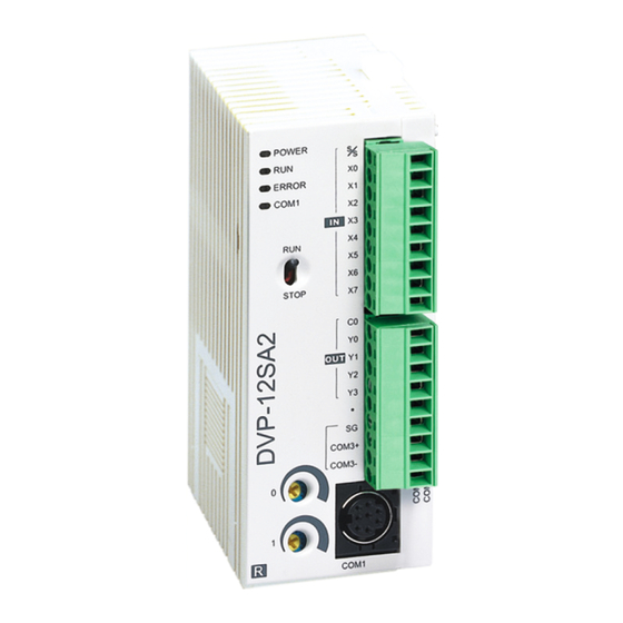
DVP28SA2 6 8.80 46 .00 60. 00 [ Figur e 1 ] Unit: mm 1. Model name 9. Nameplate 2. POWER, RUN, ERROR, 10. DC power input COM1, COM2 indicator 3. I/O terminals 11. Extension unit clip 4. I/O point/COM3 indicator 12. - Page 4 Models 12SA211R 12SA211T 28SA211R 28SA211T 28SA211S Item The diameter of grounding wire cannot be smaller than the wire diameter Grounding of terminals L and N (All DVP units should be grounded directly to the ground pole). Operation: 0 to 55°C (temp.), 5 to 95% (humidity), Pollution degree 2 Operation / Storage: -25 to 70°C (temp.), 5 to 95% (humidity) storage...
- Page 5 CO M 3+ CO M 3- C OM 3 - Note: The layout of output terminals on DVP-SA2 is different from that on DVP-SA. Dimension & Installation Please install the PLC in an enclosure with sufficient space around it to allow heat dissipation, See [Figure 3].
-
Page 6: Power Supply
Power Supply The power input of DVP-SA2 is DC. When operating DVP-SA2, please note the following points: 1. The power is connected to two terminals, 24 VDC and 0 V, and the range of power is 20.4 to 28.8 VDC. If the power voltage is less than 17.5 VDC, the PLC will stop running, all outputs will go “Off”, and the ERROR indicator will start to blink... -
Page 7: Output Point Wiring
[Figure 6] Output Point Wiring 1. DVP-SA2 has two output modules on it, relay and transistor. Be aware of the connection of shared terminals when wiring output terminals. 2. Relay output terminals Y0 to Y3 of 12SA2 relay model use C0 common port. See [Figure 7]. - Page 8 D: 1N4001 diode or equivalent component [ Figure 13b ] [ Figure 13a ] ZD:9V Zener, 5W R: 100~120Ω C: 0.1~0.24Uf [ Figure 14 ] DC power supply Emergency stop: Uses external switch Fuse: 5 to10A fuse at the shared terminal of output contacts to protect the output circuit ...
- Page 9 DC power supply Emergency stop Circuit protection fuse The output of the transistor model is “open collector”. If Y0/Y1 is set to pulse output, the output current has to be bigger than 0.1 A to ensure normal operation of the model. 1.
- Page 10 ………………………………………………………………… 繁體中文 ……………………………………………………………………… 感謝您採用台達 DVP 系列可程式控制器。DVP-SA2 分別有內建 12 點 (8 數位輸入點 + 4 數位輸出點) 與 28 點 (16 數位輸入點 + 12 數位輸出點) PLC 主機,提供豐富的指令集, 並具有 16k steps 的程式記憶體 , 可連接薄型全系列 I/O 模組與 12 點主機可連接左側高速 擴充模組,包含數位輸入∕輸出(最大輸入∕輸出擴充點數可達 480 點) 、及類比模組 (A/D、D/A 轉換及溫度單元) 。兩點 100 kHz 與兩點 10 kHz 高速脈波輸出可滿足各種應...
- Page 11 機種 DVP 12SA211R 12SA211T 28SA211R 28SA211T 28SA211S 項目 ESD (IEC 61131-2, IEC 61000-4-2): 8kV Air Discharge EFT (IEC 61131-2, IEC 61000-4-4): Power Line: 2kV, Digital I/O: 1kV, Analog & Communication I/O: 1kV RS (IEC 61131-2, IEC 61000-4-3): 26MHz ~ 1GHz, 10V/m 雜訊免疫力...
- Page 12 的銅導線。 2. 空端子請勿配線。輸入點信號線與輸出點等動力線請勿置於同一線槽內。 3. 鎖螺絲及配線時請避免微小的金屬導體掉入 PLC 內部,並在配線完成後保持散熱空間。 電源端 DVP-SA2 機種為直流電源輸入,在使用上應注意下列事項: 1. 電源請接於 24 VDC 及 0 V 兩端,電源範圍為 20.4 ~ 28.8 VDC,當電源電壓低於 17.5 VDC 時,PLC 會停止運轉,輸出全部 Off,ERROR LED 快速閃爍。 2. 當停電時間低於 10 ms 時,PLC 不受影響繼續運轉,當停電時間過長或電源電壓下降 將使 PLC 停止運轉,輸出全部 Off,當電源恢復正常時,PLC 亦自動回復運轉。 (PLC 內部具停電保持的輔助繼電器及暫存器,使用者在規劃程式設計時應特別注意使用。)...
- Page 13 安全配線回路 由於 DVP-SA2 的電源為 DC Only 的機種,因此可搭配台達之電源供應模組 (DVPPS01/DVPPS02) 提供電源給 DVP-SA2。為保護 DVPPS01/DVPPS02,建議可在 電源的輸入回路端配置如下的保護回路,配置圖請參閱英文版[Figure 4] 所示: 交流電源供應:100 ~ 240 VAC, 50/60 Hz 斷路器 緊急停止:為預防突發狀況發生,設置緊急停止按鈕,可在狀況發生時,切斷系統電源。 電源指示燈 交流電源負載 DVPPS01/DVPPS02 本體 電源回路保護用保險絲(2A) 直流電源供應輸出:24 VDC,500 mA ...
- Page 14 RS-485 建議接線 詳細接線圖請參閱英文版 [ Figure 19] 。 DVP12SA2 提供 COM2, COM3 兩組 ; DVP28SA2 僅提供 COM2 一組。 ○ ○ 主站 從站 ○ ○ 終端電阻 遮蔽線 註:1. 終端電阻建議連接於主站及最後一台從站上,且其電阻值建議為 120Ω。 2. 為確保連線品質,線材建議使用具有雙層遮蔽線之通訊雙絞線(20AWG) 。 萬年曆的精度(秒/月) 溫度 (°C/°F) 0/32 25/77 55/131 -117 -132 最大誤差(秒)...
- Page 15 …………………………………………………………………… 简体中文 …………………………………………………………………… 感谢您采用台达 DVP 系列可编程控制器。 DVP-SA2 分别有内建 12 点 (8 数字量输入点 + 4 数字量输出点)与 28 点(16 数字输入点 + 12 数字输出点)PLC 主机,提供丰富的指 令集, 并具有 16k steps 的程序内存, 可连接薄型全系列 I/O 模块与 12 点主机可连接左侧 高速扩展模块,包含数字量输入/输出(最大输入∕输出扩展点数可达 480 点) 、及模拟量 模块(A/D、D/A 转换及温度单元) 。两点 100 kHz 与两点 10 kHz 高速脉冲输出可满足各...
- Page 16 机种 DVP 12SA211R 12SA211T 28SA211R 28SA211T 28SA211S 项目 ESD (IEC 61131-2, IEC 61000-4-2): 8kV Air Discharge EFT (IEC 61131-2, IEC 61000-4-4): Power Line: 2kV, Digital I/O: 1kV, Analog & Communication I/O: 1kV RS (IEC 61131-2, IEC 61000-4-3): 26MHz ~ 1GHz, 10V/m 干扰免疫力...
- Page 17 的铜导线。 2. 空端子请勿配线。输入点信号线与输出点等动力线请勿置于同一线槽内。 3. 锁螺丝及配线时请避免微小的金属导体掉入 PLC 内部, 并在配线完成后保持散热空间。 电源端 DVP-SA2 机种为直流电源输入,在使用上应注意下列事项: 1. 电源请接于 24 VDC 及 0 V 两端, 电源范围为 20.4 ~ 28.8 VDC, 当电源电压低于 17.5 VDC 时,PLC 会停止运行,输出全部 Off,ERROR LED 快速闪烁。 2. 当停电时间低于 10 ms 时,PLC 不受影响继续运转,当停电时间过长或电源电压下降 将使 PLC 停止运转,输出全部 Off,当电源恢复正常时,PLC 亦自动回复运转。 (PLC 内部具停电保持的辅助继电器及寄存器,使用者在规划程序设计时应特别注意使用。...
- Page 18 安全配线回路 由于 DVP-SA2 的电源为 DC Only 的机种,因此可搭配台达的电源供应模块 (DVPPS01/DVPPS02) 提供电源给 DVP-SA2。为保护 DVPPS01/DVPPS02,建议可在 电源的输入回路端配置如下的保护回路,配置图请参阅英文版 [Figure 4] 所示: 交流供应电源:100 ~ 240 VAC, 50/60 Hz 断路器 紧急停止:为预防突发状况发生,设置紧急停止按钮,可在状况发生时,切断系统电源。 电源指示灯 交流电源负载 DVPPS01/DVPPS02 本体 电源回路保护用保险丝(2A) 直流供应电源输出:24 VDC,500 mA ...
- Page 19 RS-485 建议接线 详细接线图请参阅英文版 [Figure 19]。 DVP12SA2 提供 COM2, COM3 两组; DVP28SA2 仅提供 COM2 一组。 ○ ○ 主站 从站 ○ ○ 终端电阻 屏蔽线 注:1. 终端电阻建议连接于主站及最后一台从站上,且其阻值建议为 120Ω。 2. 为确保联机质量,线材建议使用具有双层屏蔽线的通讯双绞线(20AWG) 。 万年历的精度(秒/月) 温度 (°C/°F) 0/32 25/77 55/131 -117 -132 最大误差(秒) 万年历停电保持时间:一周 - 18 -...
Need help?
Do you have a question about the DVP-SA2 and is the answer not in the manual?
Questions and answers