Delta DVP-SS2 Instruction Sheet
Hide thumbs
Also See for DVP-SS2:
- Operation manual (1023 pages) ,
- Operation manual (1006 pages) ,
- Operation manual (785 pages)
Advertisement
Advertisement
Table of Contents

Subscribe to Our Youtube Channel
Related Manuals for Delta DVP-SS2


Summary of Contents for Delta DVP-SS2
- Page 1 DVP-0160030-01 20200828...
- Page 2 4 groups of high-speed (10kHz) pulse output satisfy all kinds of applications. DVP-SS2 is small in size, and can be install easily. Users do not have to install any batteries in DVP-SS2 series PLCs. The PLC programs and the latched data are stored in the flash memories.
-
Page 3: Electrical Specifications
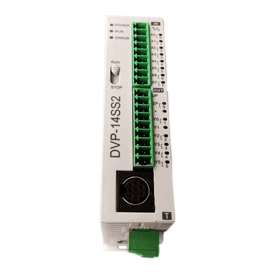
B. DVP28SS2 6 8.80 46. 00 6 0.0 0 1. Model type 8. RS-485 communication port 2. POWER, RUN, ERROR, COM1 and COM2 9. Nameplate status indicator 3. I/O terminals 10. DC power input 4. I/O point indicator 11. Extension unit clip 5. - Page 4 Input Point (single common port input) Model 12SS2, 14SS2, 28SS2 28SS2 Items Input No. X0 ~ X3 X4 ~ X7 X10 ~ X17 Input type DC (SINK or SOURCE) Input Current (± 24VDC (-15% ~ 20%),5mA 10%) Input impedance 4.7kΩ Max.
-
Page 5: Power Supply
ZP 1 ● ● Note: The layout of output terminals on DVP-SS2 is different from that on DVP-SS series. Dimension & Installation Please install the PLC in an enclosure with sufficient space around it to allow heat dissipation, See [Figure 3]. -
Page 6: Safety Wiring
[ Figure 5 ] Output Point Wiring 1. DVP-SS2 has two output modules on it, relay and transistor. Be aware of the connection of shared terminals when wiring output terminals. 2. Output terminals, Y0, Y1, and Y2, of relay models use C0 common port; Y3, Y4, and Y5 use C1 common port. - Page 7 3. The output terminals Y0~Y5, , Y0~Y13 of the transistor (NPN) model are connected to the common terminals UP and ZP. See [Figure 8a]. The output terminals Y0~Y3, Y0~Y13 on the transistor (PNP) model are connected to the common terminals UP and ZP.
- Page 8 Transistor output (NPN) Transistor output (PNP) S mall er power V DC S mal ler power V DC D: 1N4001 diode or equi valent com ponent D: 1N4001 diode or equi va lent com ponent [ F ig ure 15a ] [ F ig ure 14a ] Larger power and V DC...
- Page 9 RS-485 Wiring Master node D+ D- D+ D- D+ D- Slave node Figure 17 Terminal resistor Note: 1. Terminal resistors are suggested to be connected to master and the last slave with resistor value of 120Ω. 2.
Need help?
Do you have a question about the DVP-SS2 and is the answer not in the manual?
Questions and answers