
Subscribe to Our Youtube Channel
Related Manuals for FLIR PTU-D300


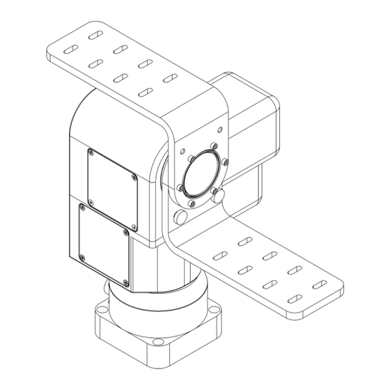
Summary of Contents for FLIR PTU-D300
- Page 1 AN-TILT Model PTU-D300 SER’S ANUAL Version 2.19 www.flir.com/mcs...
- Page 2 Pan-Tilt Unit (Model PTU-D300) User’s Manual, Version 2.19, June 25, 2012 ©1991,2006 by FLIR Commercial Systems, Inc., 890C Cowan Road, Burlingame, California 94010, (650)692-3900, FAX: (650)692-3930, www.flir.com/mcs. All rights reserved. Protected under numerous U.S. Patents including 5463432 and 5802412, and patents pending. No part of...
-
Page 3: Table Of Contents
INTRODUCTION ....................1 IMPORTANT SAFEGUARDS AND WARNINGS........2 Models ......................2 QUICK START ......................3 Overview......................3 Installation Components ................3 Basic Setup Steps..................4 INSTALLATION & INITIAL SETUP ..............5 Pan-Tilt Mounting..................5 Wiring and Connectors ................5 Power Sources....................6 RS-232 Interface and Host Settings.............7 Initial Power-up and Test ................8 Basic Pan-Tilt Unit Commands ..............8 Mounting Your Payload ................8 3.7.1 Over-the-Top Bracket Mounting............9... - Page 4 4.5.1 Reset Pan-Tilt Unit ................21 4.5.2 Default Save/Restore ..............22 4.5.3 Echo Query/Enable/Disable............22 4.5.4 Feedback Verbose/Terse/Off ............23 4.5.5 Controller Firmware Version Query ..........23 4.5.6 Outside Supply Voltage and Controller Temperature Query ..23 Power Control Commands & Queries ............23 4.6.1 Stationary Power Mode..............24 4.6.2 In-Motion Power Mode ..............24 Host Serial Port and Control ..............25 4.7.1 Configuring Host Serial Port Baud and Communications.....25...
-
Page 5: Introduction
• Robotics & computer vision. This User’s Manual provides information needed to set up and operate the PTU-D300 unit. The next section provides a brief overview to allow you to get started as quickly as possible. More detailed technical information is provided in the remaining sections. -
Page 6: Important Safeguards And Warnings
9. Refer all servicing to qualified service personnel. If the unit is damaged, remove power immediately, and contact FLIR Commercial Systems, Inc. 10. A readily accessible power disconnect shall be incorporated into the installation wiring. 11. Only use replacement parts recommended by FLIR Commercial Systems, Inc. 1.2 Models PTU-D300 Standard base configuration. -
Page 7: Quick Start
2 QUICK START 2.1 Overview Figure 1 shows a system overview. The PTU-D300 includes an integral controller and it accepts control commands from any host computer over RS-232 or RS-485. The basic D300 connections are: D300-power from a DC power source, and Pan-Tilt Control via RS232/485. -
Page 8: Basic Setup Steps
QUICK START PTU-D300 User’s Manual (v2.19) 2.3 Basic Setup Steps The following outlines the basic pan-tilt set-up and installation steps. Section 3 details each of these steps. 1. Unpack the D300 pan-tilt. Mount the pan-tilt securely. See section 3.1 for details on mounting. -
Page 9: Installation & Initial Setup
3.1 Pan-Tilt Mounting Appendix 1 shows the mounting pattern for the PTU-D300. The basic mounting pattern is four #1/4-20 socket-head cap screws in a 3.375” (85.725mm) square pattern. All four mounting screws should be used. The mount strength must be able to hold the weight of the unit plus the payload plus any additional forces exerted on the system (e.g., wind, G forces). -
Page 10: Power Sources
3.3 Power Sources The PTU-D300 requires a 12-30VDC (unregulated) power source capable of 2.25A peak. Less peak current is required if you do not use the higher motor current controls available (see Sections 4.6.1 and 4.6.2). To achieve the highest pan-tilt unit performance, use the highest motor voltage within the allowable range. -
Page 11: Rs-232 Interface And Host Settings
PTU-D300 User’s Manual (v2.19) INSTALLATION & INITIAL SETUP 3.4 RS-232 Interface and Host Settings An RS-232 terminal or host computer connects to the RS-232 Host Interface on the Pan-Tilt Unit. The host terminal or computer should be set to 9600 baud, 1 start bit, 8 data bits, 1 stop bit, and no parity. -
Page 12: Initial Power-Up And Test
Because of the heavy payload weights and high potential speeds supported by the PTU-D300, it is very important that all guidance and instructions regarding payload mounting be followed carefully. -
Page 13: Over-The-Top Bracket Mounting
PTU-D300 User’s Manual (v2.19) INSTALLATION & INITIAL SETUP 3.7.1 Over-the-Top Bracket Mounting 1. Ensure the pan-tilt has been through its calibration (at power up) so that the mounting hub is in a known home position. 2. Orient the bracket so the horizontal part of the bracket is topmost. When in the proper orientation, a peg in the bracket will locate into a hole in the D300 mounting hub. -
Page 14: Payload Wiring Connections
Though the PTU-D300 unit is rated to a maximum load of 70 lbs, the distribution of the load affects the actual load capable of being moved by the pan-tilt unit. The steps to determine whether your load and its positioning (e.g., center of gravity) are within the maximum load capacity and... -
Page 15: Command Reference
PTU-D300 User’s Manual (v2.19) COMMAND REFERENCE 4 COMMAND REFERENCE This section describes the pan-tilt unit command set. Each command has a section that provides a brief functional description, a format (syntax) description, examples, and related topics. When controlling the pan-tilt unit from a terminal, a complete menu of pan-tilt commands can be obtained by entering the character “?”. -
Page 16: Offset Position (Relative Offset)
COMMAND REFERENCE PTU-D300 User’s Manual (v2.19) Related Topics • Position (relative offset and desired position queries): See Section 4.3.2 • Position resolution (units): See Section 4.3.3 • Position limits: See Section 4.3.4 • Position execution modes: See Sections 4.3.6, 4.3.7 and 4.3.8 •... -
Page 17: Limit Position Queries
PTU-D300 User’s Manual (v2.19) COMMAND REFERENCE Related Topics • Factory options are available to achieve higher resolution or accuracy. 4.3.4 Limit Position Queries Description Queries return the axis position bounds determined upon unit reset. Syntax Query minimum pan position: PN<delim>... -
Page 18: Immediate Position Execution Mode
COMMAND REFERENCE PTU-D300 User’s Manual (v2.19) Related Topics • Position commands: See Sections 4.3.1 and 4.3.2 4.3.6 Immediate Position Execution Mode Description Instructs pan-tilt unit to immediately execute positional commands. This is the default mode. Syntax I<delim> Example For the below commands, the pan axis will immediately execute the pan... -
Page 19: Await Position Command Completion
PTU-D300 User’s Manual (v2.19) COMMAND REFERENCE 4.3.8 Await Position Command Completion Description Awaits the completion of the last issued pan and tilt axis position commands. Used to coordinate axis motions. Syntax A<delim> Example The following commands instruct the pan axis to move to a position, then... -
Page 20: Monitor (Autoscan) Command
COMMAND REFERENCE PTU-D300 User’s Manual (v2.19) 4.3.10 Monitor (Autoscan) Command Description Command defines and initiates repetitive monitoring (scanning) of the pan- tilt. Autoscanning is immediately terminated upon receipt of a character from the host computer, and the pan-tilt is sent to its home position. -
Page 21: Speed Control Commands & Queries
PTU-D300 User’s Manual (v2.19) COMMAND REFERENCE PP500 * TP400 * XS0 * PP600 * TP800 * 4.4 Speed Control Commands & Queries 4.4.1 Speed Control & Relevant Terms The Pan-Tilt Unit provides for precise control of axis speed and acceleration. This subsection briefly describes how speed control is performed and it introduces relevant terms. -
Page 22: Delta Speed (Relative Offset)
COMMAND REFERENCE PTU-D300 User’s Manual (v2.19) Syntax Query desired pan speed: PS<delim> Set desired pan speed: PS<positions/sec><delim> Query desired tilt speed: TS<delim> Set desired tilt speed: TS<positions/sec><delim> Example The following commands instruct the pan axis to move to the far left, then... -
Page 23: Acceleration
PTU-D300 User’s Manual (v2.19) COMMAND REFERENCE • Speed bounds: See Section 4.4.6 4.4.4 Acceleration Description Specify or query axis acceleration and deceleration for speeds above the base speed. Acceleration is specified in positions/second Syntax Query desired pan acceleration: PA<delim> Set desired pan acceleration: PA<positions/sec... -
Page 24: Speed Bounds
COMMAND REFERENCE PTU-D300 User’s Manual (v2.19) Related Topics • Position resolution (units): See Section 4.3.3 • Acceleration: See Sections 4.4.1 and 4.4.4 • Speed bounds: See Section 4.4.6 • Changes in the base rate cannot be made on-the-fly since it takes several seconds to recompute the internal tables used to rapidly execute speed ramping. -
Page 25: Unit Commands
PTU-D300 User’s Manual (v2.19) COMMAND REFERENCE speed. In this mode, the speed command specifies a signed velocity in which the sign determines the direction of axis movement, and the ordinal value specifies the speed of movement in this direction. In this mode, if the commanded speed is negative, the axis is automatically commanded to the minimum axis position. -
Page 26: Default Save/Restore
COMMAND REFERENCE PTU-D300 User’s Manual (v2.19) position of 0 (see Section 4.3.4), hence position commands in limit enabled mode (see Section 4.3.5) will return an illegal position command feedback. Syntax Performs Reset calibration: R<delim> Reset modes (saved in internal EEPROM for power up reset control): Disable reset upon power up: RD<delim>... -
Page 27: Feedback Verbose/Terse/Off
Query specifies the version and copyrights for the pan-tilt controller firmware. Syntax V<delim> Example * Pan-Tilt Controller v2.12.1d1(C14/E), (C)2003 FLIR Commercial Systems, Inc., All Rights Reserved 4.5.6 Outside Supply Voltage and Controller Temperature Query Description The pan-tilt controller includes sensors for the internal temperature and the input voltage supplied to the pan-tilt. -
Page 28: Stationary Power Mode
COMMAND REFERENCE PTU-D300 User’s Manual (v2.19) 4.6.1 Stationary Power Mode Description Set and query the current level applied to axis motors when not in-transit. Syntax Query pan hold power mode: PH<delim> Regular pan hold power mode: PHR<delim> Low pan hold power mode: PHL<delim>... -
Page 29: Host Serial Port And Control
PTU-D300 User’s Manual (v2.19) COMMAND REFERENCE Example PM * Pan in REGULAR move power mode PML * PM * Pan in LOW move power mode Related Topics • It is not recommended that an axis be in transit more than 20% of the time when in High Move Power Mode (i.e., a 20% duty cycle). -
Page 30: Step Modes
COMMAND REFERENCE PTU-D300 User’s Manual (v2.19) The following command sets the host serial port RS232/RS485 to a baud rate of 19,200 bits/second (8 data bits per byte, no parity, no handshaking), a 30ms delay between bytes output from the pan-tilt controller, and the power up baud rate overrides the default and is set at 19,200 baud. -
Page 31: Special Configurations
PTU-D300 User’s Manual (v2.19) SPECIAL CONFIGURATIONS 5 SPECIAL CONFIGURATIONS 5.1 High-Speed Operation This section discusses how to improve high speed pan-tilt unit performance for your load. The primary factors that affect high speed operation are: • Load weight, weight distribution and dynamics •... -
Page 32: Ptu Options
For OEM applications, internal D300 wiring can be brought out on FFC (flat flex connectors) to provide for additional control signals. For example, other serial devices attached or proximal to the pan-tilt may require other RS232 serial ports. Please contact FLIR Commercial Systems, Inc. for additional information on these custom configurations. -
Page 33: Ptu Network Connections
RS-232, RS-485 connections may be simply made using an external RS-232 to RS-485 converter. FLIR Commercial Systems, Inc. has tested/qualified two converters: ATEN IC-485S and Moxa A50 which both require a flipped RJ-12 connector (such as a standard phone cord). It is important to note that the network should be terminated using 120... -
Page 34: Unit Select/Deselect
NETWORKING PTU-D300 User’s Manual (v2.19) controllers may be set to the same unit ID number). A unit ID of zero may be used to put a PTU controller back in interactive (non- networked) mode. Syntax Query current PTU network unit ID: U<delim>... -
Page 35: Specifications
PTU-D300 User’s Manual (v2.19) Appendix A.: SPECIFICATIONS A. SPECIFICATIONS A.1 D300 Mechanical Dimensions page 31... -
Page 36: D300 Payload Bracket Dimensions
PTU-D300 User’s Manual (v2.19) Appendix A.: SPECIFICATIONS A.2 D300 Payload Bracket Dimensions page 32... -
Page 37: D300 Base Connector Wiring
PTU-D300 User’s Manual (v2.19) Appendix A.: SPECIFICATIONS A.3 D300 Base Connector Wiring page 33... -
Page 38: D300 Payload Wiring Pl01
PTU-D300 User’s Manual (v2.19) Appendix A.: SPECIFICATIONS A.4 D300 Payload Wiring PL01 page 34... -
Page 39: D300 Payload Wiring Pl02
PTU-D300 User’s Manual (v2.19) Appendix A.: SPECIFICATIONS A.5 D300 Payload Wiring PL02 page 35... -
Page 40: D300 Payload Mounting
PTU-D300 User’s Manual (v2.19) Appendix A.: SPECIFICATIONS A.6 D300 Payload Mounting page 36... -
Page 41: Regulatory Information
REGULATORY INFORMATION Electromagnetic Interference (EMI) is any signal or emission, radiated in free space or conducted along power or sig- nal leads that endangers the function of a radio navigation or other safety service or seriously degrades, obstructs, or repeatedly interrupts a licensed radio communications service. Class A Class A equipment has been tested and found to comply with the limits for a Class A digital device, pursuant to Part 15 of the FCC Rules. -
Page 42: Limited Warranty
FLIR Commercial Systems, Inc. warrants this product against defects in material or workmanship, as follows: For a period of one year from date of purchase, FLIR Commercial Systems, Inc. will repair the defective product and provide new or rebuilt replacements at no charge. Warranty repairs require the issuance of a repair authorization number from FLIR Commercial Systems, Inc.
Need help?
Do you have a question about the PTU-D300 and is the answer not in the manual?
Questions and answers