Burkert 2712 Series Operating Instructions Manual
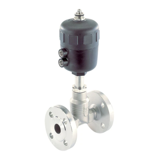
Piston controlled flat-seat valve
Hide thumbs
Also See for 2712 Series:
- Operating instructions manual (40 pages) ,
- Operating instructions manual (28 pages) ,
- Operating instructions manual (52 pages)
Table of Contents
Advertisement
Available languages
Available languages
Quick Links
Type 2712
Piston controlled flat-seat valve
Kolbengesteuertes Geradsitzventil
Soupape à tête droite commandée par piston
Actuator sizes 175 mm - 225 mm
Nominal diameters DN 65, DN 80, DN 100
Antriebsgrößen 175 mm - 225 mm
Nennweiten DN 65, DN 80, DN 100
Tailles de mécanisme 175 mm - 225 mm
Diamètre nominal DN 65, DN 80, DN 100
Operating Instructions
Bedienungsanleitung
Manuel d'utilisation
Advertisement
Table of Contents

Subscribe to Our Youtube Channel
Related Manuals for Burkert 2712 Series


Summary of Contents for Burkert 2712 Series
- Page 1 Type 2712 Piston controlled flat-seat valve Kolbengesteuertes Geradsitzventil Soupape à tête droite commandée par piston Actuator sizes 175 mm - 225 mm Nominal diameters DN 65, DN 80, DN 100 Antriebsgrößen 175 mm - 225 mm Nennweiten DN 65, DN 80, DN 100 Tailles de mécanisme 175 mm - 225 mm Diamètre nominal DN 65, DN 80, DN 100 Operating Instructions...
- Page 2 We reserve the right to make technical changes without notice. Technische Änderungen vorbehalten. Sous réserve de modifications techniques. © Bürkert Werke GmbH & Co. KG, 200 - 2017 Operating Instructions 1706/ _EU-EN_008 / Original DE...
-
Page 3: Table Of Contents
ONTENTS Contents of the overall operating instructions for the Piston controlled flat-seat valve Actuator sizes 175 - 225 mm Nominal diameters DN 65, DN 80, DN 100 GENERAL NOTES ............................................... Symbols .................................................. Safety information ........................................... Scope of delivery ............................................Warranty conditions .......................................... - Page 4 ONTENTS 2 - 2712 big...
-
Page 5: General Notes
ENERAL OTES GENERAL NOTES Symbols .................................................. Safety notes ..............................................Scope of delivery ............................................Warranty conditions ..........................................2712 big - 3... -
Page 6: Symbols
ENERAL OTES Symbols The following symbols are used in these operating instructions: marks a work step thet you must carry out. ATTENTION! marks notes on whose non-observance your health or the functioning of the device will be endangered. NOTE marks important additional information, tips and recommendations. Safety notes Please observe the notes in these operating instructions together with the conditions of use and permitted data that are specified in the data sheets for the pneumatically actuated valve and for the Top Control , in... -
Page 7: Technical Data
ECHNICAL TECHNICAL DATA Construction of the control valve ..................................Media ................................................... 2712 big - 5... -
Page 8: Construction Of The Control Valve
ECHNICAL Construction of the control valve 2/2-way piston controlled valve with control cone and Y-housing. Control function A (closed by spring force in rest position) Control function B (open in rest position) Actuator material: PA (polyamide) Housing material: stainless steel 316L Seal materials: steel/steel (1.4571) or PTFE/steel Media... -
Page 9: Comissioning
OMMISSIONING COMMISSIONING Installation of the valve ......................................... 2712 big - 7... -
Page 10: Installation
OMMISSIONING Installation of the valve Installation in any orientation, but preferably with the actuator above. Observe the direction of flow: with control valves the general rule is: inlet under seat! Clean piping from contamination! Before attaching the valve housing, make sure the piping is aligned! If the housing is to be welded on, make absolutely sure that the drive unit is removed beforehand. -
Page 11: Maintenance And Servicing
AINTENANCE AND ERVICING MAINTENANCE AND SERVICING Malfunctions ..............................................Replacing the control cone ..................................... Replacement of valve seat ....................................... Spare parts sets ............................................2712 big - 9... -
Page 12: Malfunctions
AINTENANCE AND ERVICING Malfunctions Possible malfunctions concerning the actuator are listed in the operatinginstructions for the Top Control . ATTENTION! Repairs to the actuator may only be carried out in the factory. Contact your Bürkert branch or our Customer Service directly: Bürkert Fluid Control Systems Sales Center Christian-Bürkert-Str. - Page 13 AINTENANCE AND ERVICING Assembly Support the control cone at ists cylindrical part with the aid of a V-block or the like. Place the dowel pin in postion and carefully knock in with a hammer. Bring the dowel pin into a central position relative to the spindle axis (knock it in up to the end of the recess).
-
Page 14: Replacement Of Valve Seat
AINTENANCE AND ERVICING Replacement of valve seat To replace the valve seat, the actuator must be disassembled from the housing. For disassembly and assembly, see "Replacing the control cone". Unscrew the old housing seat using the assembly tool and a spanner. -
Page 15: Spare Parts Sets For Standard Valves
AINTENANCE AND ERVICING Spare parts sets for standard valves A control cone set, a control fittings set and a set of seals (packed gland) are available as spares. To disassemble the actuator fromt he housing or reassemble it, proceed as under installation. NOTE Before disassembling or opening the device, always interrupt the supply of medium and release the pressure in the piping system. - Page 16 AINTENANCE AND ERVICING Control cone set Actuator Steel/Steel PTFE/steel housing seat size Order no. Order no. Ø175 155 625 155 637 Ø175 155 627 155 639 Ø175 155 630 155 642 Ø225 155 628 155 640 Ø225 155 631 155 643 Ø225 155 633 155 645...
- Page 17 NHALT Inhaltsverzeichnis der Gesamtbedienungsanleitung des kolbengesteuerten Geradsitzregelventils mit Antriebsgrößen 175 mm und 225 mm und Nennweiten DN 65, DN 80, DN 100 ALLGEMEINE HINWEISE ........................................Darstellungsmittel ..........................................Sicherheitshinweise .......................................... Lieferumfang ..............................................Garantiebestimmungen ....................................... TECHNISCHE DATEN ..........................................Aufbau des Regelventils ......................................Medien ..................................................
- Page 18 NHALT 16 - 2712 big...
- Page 19 LLGEMEINE INWEISE ALLGEMEINE HINWEISE Darstellungsmittel ..........................................Sicherheitshinweise ..........................................Lieferumfang ..............................................Garantiebestimmungen ....................................... 2712 big - 17...
- Page 20 LLGEMEINE INWEISE Darstellungsmittel In dieser Betriebsanleitung werden folgende Darstellungsmittel verwendet: markiert einen Arbeitsschritt, den Sie ausführen müssen ACHTUNG! kennzeichnet Hinweise, bei deren Nichtbeachtung Ihre Gesundheit oder die Funktionsfä- higkeit des Gerätes gefährdet ist HINWEIS kennzeichnet wichtige Zusatzinformationen, Tipps und Empfehlungen Sicherheitshinweise Bitte beachten Sie die Hinweise dieser Betriebsanleitung sowie die Einsatzbedingungen und zulässigen Daten, die in den Datenblättern des Ventils mit pneumatischem Antrieb und des Top Control spezifiziert...
- Page 21 ECHNISCHE ATEN DES ENTILS TECHNISCHE DATEN Aufbau des Regelventils ......................................Medien ................................................... 2712 big - 19...
- Page 22 ECHNISCHE ATEN DES ENTILS Aufbau des Regelventils 2/2-Wege-Kolbensteuerventil mit Regelkegel und Schrägsitzgehäuse Steuerfunktion A (in Ruhestellung durch Federkraft geschlossen) Steuerfunktion B (in Ruhestellung geöffnet) Antriebswerkstoff: PA (Polyamid) Gehäusewerkstoff: Edelstahl 316L Dichtwerkstoffe: Stahl/Stahl (1.4571) oder PTFE/Stahl Medien Flüssige u. gasförmige Medien, die den Gehäuse- und Dichtwerkstoff nicht angreifen. Steuermedium: Instrumentenluft, Klasse 3 nach DIN ISO 8573-1 HINWEIS Die zugelassenen Betriebsdrücke und Medientemperaturen sind dem Datenblatt bzw.
- Page 23 NBETRIEBNAHME DES ENTILS INBETRIEBNAHME Einbau des Ventils ............................................. 2712 big - 21...
- Page 24 NBETRIEBNAHME DES ENTILS Einbau des Ventils Einbaulage beliebig, bevorzugt Antrieb nach oben. Beachten Sie die Durchflußrichtung, bei Regelventilen gilt generell: Anströmung unter Sitz! Säubern Sie die Rohrleitungen von Verunreinigungen! Achten Sie vor Anschluß des Ventilgehäuses auf fluchtende Rohrleitungen! Entfernen Sie bei Schweißgehäusen den Antrieb unbedingt vor dem Einschweißen des Gehäuses. Vorgehensweise: 1.
- Page 25 NSTANDHALTUNG UND ARTUNG DES ENTILS INSTANDHALTUNG WARTUNG Störungen ................................................ Austausch des Regelkegels ....................................Austausch des Ventilsitzes ..................................... Ersatzteilsätze für Standardventile ................................2712 big - 23...
- Page 26 NSTANDHALTUNG UND ARTUNG DES ENTILS Störungen Mögliche Störungen seitens der Ansteuerung sind in der Bedienungsanleitung des Top Control aufgeführt. ACHTUNG! Reparaturen am Antrieb dürfen nur im Werk durchgeführt werden. Wenden Sie sich hierzu an Ihre Bürkert Niederlassung oder direkt an unseren Kundenservice: Bürkert Fluid Control Systems Sales Center Christian-Bürkert-Str.
- Page 27 NSTANDHALTUNG UND ARTUNG DES ENTILS Montage Stützen Sie den Regelkegel an seinem zylindrischen Teil mit Hilfe eines Prismas oder ähnlichem ab. Setzen Sie den Spannstift an und klopfen Sie ihn vorsichtig mit dem Hammer ein. Bringen Sie den Spannstift in zur Spindelachse gesehen mittige Lage (klopfen Sie ihn bis zum Ende der Ansenkung ein).
- Page 28 NSTANDHALTUNG UND ARTUNG DES ENTILS Austausch des Ventilsitzes Zum Austausch des Ventilsitzes muß der Antrieb vom Gehäuse demontiert werden. Demontage und Mon- tage siehe "Austausch des Regelkegels" Schrauben Sie den alten Gehäusesitz mit Hilfe des Montagewerkzeug Montagewerkzeuges und einem Schraubenschlüssel aus. Säubern Sie Gewinde und Dichtfläche im Gehäuse mit Preßluft.
- Page 29 NSTANDHALTUNG UND ARTUNG DES ENTILS Ersatzteilsätze für Standardventile Als Ersatzteile steht ein Regelkegelsatz, eine Regelgarnitur und ein Dichtungssatz Stopfbuchse zur Verfügung. Zur Demontage bzw. Montage des Antriebes vom Gehäuse gehen Sie wie unter dem Punkt Einbau beschrieben vor. HINWEIS Unterbrechen Sie vor dem Ausbau oder dem Öffnen des Gerätes immer die Mediumszufuhr und bauen Sie den Druck im Leitunssystem ab.
- Page 30 NSTANDHALTUNG UND ARTUNG DES ENTILS Regelkegelsatz DN Sitz Antriebs- Stahl/Stahl PTFE/Stahl Gehäuse größe Best.-Nr. Best.-Nr. Ø175 155 625 155 637 Ø175 155 627 155 639 Ø175 155 630 155 642 Ø225 155 628 155 640 Ø225 155 631 155 643 Ø225 155 633 155 645...
- Page 31 ABLE DES ATIÈRES Table des matières des instructions de service complètes de la soupape à tête droite commandée par piston Tailles de mécanisme 175 mm et 225 mm Diamètre nominal DN 65, DN 80, DN 100 REMARQUES GENERALES ......................................Représentation ............................................
- Page 32 ABLE DES ATIÈRES 30 - 2712 big...
- Page 33 EMARQUES ENERALES REMARQUES GENERALES Représentation ............................................Consignes générales de sécurité .................................. Fourniture ................................................ Clauses de garantie ........................................... 2712 big - 31...
- Page 34 EMARQUES ENERALES Représentation Les symboles de représentation suivants sont utilisés dans cette notice de service: marque une étape de travail devant être exécutée ATTENTION! caractérise des instructions dont l'inobservation entraîne des risques pour votre santé ou met en cause la fonctionnalité de l'appareil. REMARQUE caractérise des informations supplémentaires imprtantes, des conseils et des recommandations.
- Page 35 ARACTERISTIQUES ECHNIQUES CARACTERISTIQUES TECHNIQUES Structure de la soupape de réglage ................................Fluides ................................................... 2712 big - 33...
- Page 36 ARACTERISTIQUES ECHNIQUES Structure de la soupape de réglage Soupape 2/2 voies commandée par piston avec pointeau de réglage et boîtier incliné Fonction de commande A (fermée en position de repos par effet de ressort) Fonction de commande B (ouverte en position de repos) Matière du mécanisme: PA (polyamide) Matière du boîtier:...
- Page 37 ISE EN SERVICE MISE EN SERVICE Montage de la soupape ........................................2712 big - 35...
- Page 38 ISE EN SERVICE Montage de la soupape Position de montage quelconque, de préférence, mécanisme vers le haut. Tenir compte du sens du débit, pour les soupapes de réglage, l'écoulement a lieu en général sous le siège! Nettoyer les tuyauteries des impuretés! Avant de raccorder le boîtier de la soupape, veiller à...
- Page 39 AINTENANCE ET ENTRETIEN MAINTENANCE ET ENTRETIEN Pannes .................................................. Echange du pointeau de réglage ..................................Echange du siège de la soupape ..................................Jeux de pièces de rechange ....................................2712 big - 37...
- Page 40 AINTENANCE ET ENTRETIEN Pannes Les pannes susceptibles de survenir du côté de l'excitation figurent dans les instructions de service du Top Control . ATTENTION! Les réparations du mécanisme ne doivent être faites qu'en usine. S'adresser à cet effet à votre succursale Bürkert ou directement à notre service clientèle. Bürkert Fluid Control Systems Sales Center Christian-Bürkert-Str.
- Page 41 AINTENANCE ET ENTRETIEN Montage Etayer le pointeau de réglage à sa partie cylindrique à l'aide d'un prisme ou objet similaire. Mettre la goupille et l'insérer en la tapant prudemment avec le marteau. Enfoncer la goupille en position médiane regardant l'axe de la broche (l'enfoncer jusqu'au bout du chanfrein) Avant de remoter le mécanisme (en position ouverte de la soupape), graisser le raccord à...
- Page 42 AINTENANCE ET ENTRETIEN Echange du siège de soupape Pour changer le siège de la soupape, le mécanisme de commande doit être démonté du boîtier. Pour le démontage, voir "Echange du pointeau de réglage". Dévisser l'ancien siège de boîtier à l'aide de l'outil de montage Outil de montage et d'une clé...
- Page 43 AINTENANCE ET ENTRETIEN Jeux de pièces de rechange pour soupapes standard Sont disponibles comme pièces de rechange, un jeu de pointeaux, une garniture de réglage et un jeu de joints presse-étoupe. Pour démonter ou monter le mécanisme du boîtier, il faut procéder comme décrit dans Montage de la soupape.
- Page 44 AINTENANCE ET ENTRETIEN Jeu de pointeau de réglage Boîtier DN Siège Taille du acier/acier PTFE/acier mécanis- cde. cde. Ø175 155 625 155 637 Ø175 155 627 155 639 Ø175 155 630 155 642 Ø225 155 628 155 640 Ø225 155 631 155 643 Ø225 155 633...
- Page 46 www.burkert.com...
Need help?
Do you have a question about the 2712 Series and is the answer not in the manual?
Questions and answers