Table of Contents
Advertisement
Quick Links
Download this manual
See also:
User Manual
Advertisement
Chapters
Table of Contents

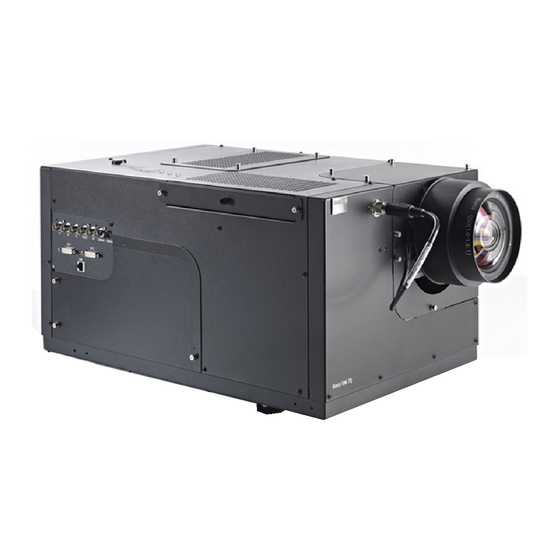
Summary of Contents for Barco SIM 7D
- Page 1 Rugged frame Installation manual SIM 7D and SIM 7Q R9898415 R59770377/00 07/04/2009...
- Page 2 Barco nv Simulation Division Noordlaan 5, B-8520 Kuurne Phone: +32 56.36.82.11 Fax: +32 56.36.84.86 E-mail: info@barco.com Visit us at the web: www.barco.com Printed in Belgium...
- Page 3 The period of guarantee begins on the date of transfer of risks, in the case of special systems and software on the date of commissioning, at latest 30 days after the transfer of risks. In the event of justified notice of complaint, Barco can repair the fault or provide a replacement at its own discretion within an appropriate period.
-
Page 5: Table Of Contents
Table of contents TABLE OF CONTENTS 1. Safety ....................... .. 3 Safety guidelines and warnings . - Page 6 Table of contents R59770377 RUGGED FRAME 07/04/2009...
-
Page 7: Safety
1. Safety 1. SAFETY Safety guidelines and warnings ARNING When lifting the assembly always take the necessary precautions ! ARNING Always respect the safety warnings and cautions present in this manual. R59770377 RUGGED FRAME 07/04/2009... - Page 8 1. Safety R59770377 RUGGED FRAME 07/04/2009...
-
Page 9: Kit Description
2. Kit description 2. KIT DESCRIPTION Overview • Introduction • Kit content • Dimensions Introduction Purpose of rugged frame This rugged frame is designed for simulation application. It ensures rigidity, prevents projector and lens from moving and avoids lens holder from breaking in case of motion base platform (e.g. flight simulator). AUTION Once the rugged frame has been mounted, you can not use the lens shift, zoom and focus func- tionality of the projector anymore! It would damage the motors. -
Page 10: Kit Content
2. Kit description Kit content Drawing Image 2-2 Kit content: general drawings R59770377 RUGGED FRAME 07/04/2009... -
Page 11: Kit Content: Parts
2. Kit description Kit content (1) Image 2-3 Kit content: parts Label Part number Description of part number Quantity B590696 Box containing rugged frame R864177 Front frame R858011 Bottom frame Table 2-1 Kit content: table 1 R59770377 RUGGED FRAME 07/04/2009... -
Page 12: Kit Content: Parts
2. Kit description Kit content (2) Image 2-4 Kit content: parts Label Part number Description of part number Quantity A577529 Plain washers DIN125A M8 A576085 Hexagon head screw DIN933 M8 V3673807 Plain washers DIN9021 M6 B362188 T-nut M6 B362189 Low head socket cap screw DIN7984 M6 R367380 Plain washers DIN125A M6 R864195... -
Page 13: Dimensions
2. Kit description Dimensions General dimensions Image 2-5 Dimensions: general R59770377 RUGGED FRAME 07/04/2009... -
Page 14: Dimensions: Sim 7Q
2. Kit description SIM 7Q rugged frame Image 2-6 Dimensions: SIM 7Q SIM 7D rugged frame Image 2-7 Dimensions: SIM 7D R59770377 RUGGED FRAME 07/04/2009... -
Page 15: Mounting The Rugged Frame
3. Mounting the rugged frame 3. MOUNTING THE RUGGED FRAME Overview • Inserting a T-nut inside the rugged frame • Fixing the front frame to the bottom frame • Mounting the projector to the rugged frame • Fixing the lens clamp assembly to the projector lens •... -
Page 16: Frame Bracket
3. Mounting the rugged frame Image 3-2 Frame bracket 3. Use 2 corner frames R858010, 8 screws B362189, 16 washers R367380 and 8 T-nuts B362188 to fix the front frame to the bottom frame. See image 3-3 Image 3-3 Corner frame side view Note: same parts are used on the other side to fix the frames R59770377 RUGGED FRAME 07/04/2009... -
Page 17: Mounting The Projector To The Rugged Frame
3. Mounting the rugged frame 4. Use the same parts as above to reinforce the front frame Image 3-4 Corner frame bottom view 5. Make sure that all screws are tightened Mounting the projector to the rugged frame Necessary tools Nut spanner 13 mm How to mount the projector to the rugged frame? 1. -
Page 18: Fixing The Lens Clamp Assembly To The Projector Lens
3. Mounting the rugged frame Image 3-5 Note: Make sure that the projector’s feet holes are aligned with axis of rugged frame holes 3. Use 3 screws A576085 and 3 washers A577529 to fix the projector to the bottom frame Fixing the lens clamp assembly to the projector lens Necessary tools •... -
Page 19: Position Of The Tightening Screws Of The Lens Clamps
3. Mounting the rugged frame Image 3-7 Image 3-6 Fix the lens clamp to the lens Position of the tightening screws of the lens clamps 2. Fix the lens clamp assembly (vertical position) to the front frame using 3 screws B362189, 3 washers V3673807 and 3 T-nuts B362188 but do not tighten the screws Image 3-8 Fixing the lens clamp assembly... -
Page 20: Fixing The Bottom Frame
3. Mounting the rugged frame Horizontal shift Vertical shift 4. Tighten all the screws Image 3-9 Tightening of all the seven screws Fixing the bottom frame Necessary tools Nut spanner 13 mm How to fix the assembly to its support? 1. -
Page 21: Fixing The Bottom Frame
3. Mounting the rugged frame Image 3-10 Fixing the bottom frame 2. Tighten all the screws R59770377 RUGGED FRAME 07/04/2009... - Page 22 3. Mounting the rugged frame R59770377 RUGGED FRAME 07/04/2009...
-
Page 23: Index
Index INDEX bottom frame lens clamp assembly fixing projector content mounting description projector dimensions lens clamp assembly fixing rugged frame 11, 13 bottom frame projector front frame bottom frame fixing safety safety guidelines introduction T-nut 5–6 content 5–6 description 5–6 warnings R59770377 RUGGED FRAME 07/04/2009... - Page 24 Index R59770377 RUGGED FRAME 07/04/2009...
-
Page 25: List Of Images
Dimensions: SIM 7D ........


Need help?
Do you have a question about the SIM 7D and is the answer not in the manual?
Questions and answers