Barco SIM 7Q HB User Manual
Sim 7q series
Hide thumbs
Also See for SIM 7Q HB:
- Brochure & specs (2 pages) ,
- User manual (290 pages) ,
- Installation manual (25 pages)

Related Manuals for Barco SIM 7Q HB


Summary of Contents for Barco SIM 7Q HB
-
Page 1: User Guide
SIM 7Q series User Guide R92112011 R92112012 R92112013 R92112021 R92112022 R92112023 R92112161 R92112162 R92112163 R9211222 R9211224 R59770066/11 07/10/2013... - Page 2 Factory: Barco nv Advanced Visualization Systems Noordlaan 5, B-8520 Kuurne Phone: +32 56.36.82.11 Fax: +32 56.36.84.86 Support: www.barco.com/esupport Visit us at the web: www.barco.com Printed in Belgium...
-
Page 3: Software License Agreement
The period of guarantee begins on the date of transfer of risks, in the case of special systems and software on the date of commissioning, at latest 30 days after the transfer of risks. In the event of justified notice of complaint, Barco can repair the fault or provide a replacement at its own discretion within an appropriate period. - Page 4 GNU-GPL code If you would like a copy of the GPL source code contained in this product shipped to you on CD, please contact Barco. The cost of preparing and mailing a CD will be charged. Trademarks Brand and product names mentioned in this manual may be trademarks, registered trademarks or copyrights of their respective holders.
-
Page 5: Table Of Contents
Table of contents TABLE OF CONTENTS 1. Introduction ......................5 About the projector . - Page 6 Table of contents 7.4.4 Save as (create a custom file) ....................95 7.4.5 Rename file .
- Page 7 Table of contents 7.8.11 Gray Level Definition......................205 7.8.11.1 Description.
- Page 8 Table of contents R59770066 SIM 7Q SERIES 07/10/2013...
-
Page 9: Introduction
1. Introduction 1. INTRODUCTION Overview • About the projector • About the manual R59770066 SIM 7Q SERIES 07/10/2013... -
Page 10: About The Projector
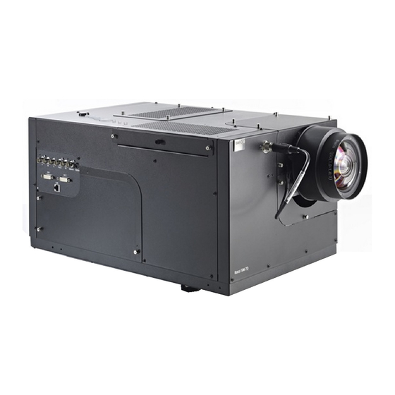
1. Introduction About the projector SIM 7Q series projectors The SIM 7Q series projectors are LCoS (Liquid Crystal on Silicon) based high resolution projectors developed for high demanding simulation applications. Image 1-1 SIM 7Q series: smearing reduction and blur reduction R59770066 SIM 7Q SERIES 07/10/2013... -
Page 11: About The Manual
For the latest version of the product manuals, see http://www.barco.com. Clarification of the term “SIM 7Q series” used in this document When referring in this document to the term “SIM 7Q series” it is meant that the content is applicable for the following Barco products: •... - Page 12 1. Introduction Font overview • Buttons are indicated in bold, e.g. OK. • Menu items are indicated in italic. • Step related notes, tips, warnings or cautions are printed in italic. • Procedure related notes, tips, warnings or cautions are printed in bold between 2 lines preceded by the corresponding icon. R59770066 SIM 7Q SERIES 07/10/2013...
-
Page 13: Packaging
2. Packaging 2. PACKAGING Overview • Unpacking R59770066 SIM 7Q SERIES 07/10/2013... -
Page 14: Unpacking
Never transport the projector with the lens mounted on it ! Always remove the lens before transporting the projector. AUTION Make sure that the projection lens has the one-to-one match with the projector and please contact Barco in case of replacement of the projection lens. R59770066 SIM 7Q SERIES 07/10/2013... -
Page 15: Unpacking The Cardboard Box: Exploded View
2. Packaging How to unpack the projector ? 1. Release the cord straps. PULL TO OPEN Image 2-2 2. Remove the assembly from the pallet 3. Open the outer cardboard box 4. Remove the two smaller box, which contains: User guide and Safety manual RCU + batteries power cords projection lens... - Page 16 2. Packaging R59770066 SIM 7Q SERIES 07/10/2013...
-
Page 17: Installation Guidelines
3. Installation guidelines 3. INSTALLATION GUIDELINES Overview • Safety warnings • Installation guidelines R59770066 SIM 7Q SERIES 07/10/2013... -
Page 18: Safety Warnings
3. Installation guidelines Safety warnings ARNING Before installing the projector, first read the safety instructions in the safety manual (R5975258) delivered with the projector. Insure that the room can be easily evacuated in case of a lamp explosion. Mercury vapor warnings Keep the following warnings in mind when using the projector. -
Page 19: Installation Guidelines
filters as this will dramatically reduce the lifetime of the consumables. It is advised to replace the air filters at any lamp change. Barco reserves itself the right to refuse warranty replacement of consumables if they have been used in a projector with dirty air filters. -
Page 20: Which Screen Type
3. Installation guidelines Which screen type ? There are two major categories of screens used for projection equipment. Those used for front projected images and those for rear projection applications. Screens are rated by how much light they reflect (or transmit in the case of rear projection systems) given a determined amount of light projected toward them. -
Page 21: Installation
4. Installation 4. INSTALLATION Overview • Dimensions • Fixation points at the bottom of the projector • Projector tilt • RCU battery installation • Lens installation • Projector configuration • Connections R59770066 SIM 7Q SERIES 07/10/2013... -
Page 22: Dimensions
4. Installation Dimensions Projector dimensions and weight Dimensions are given in mm and inch (1inch = 25.4 mm) Weight (without lens) : approx. 27 kg (59.5 lbs) FRONT VIEW BOTTOM VIEW LEFT SIDE VIEW air exhaust BACK VIEW air filter air filter TOP VIEW Image 4-1... -
Page 23: Fixation Points At The Bottom Of The Projector
4. Installation Fixation points at the bottom of the projector Describing the fixation points To fix the projector to its support, three bolts can be screwed into the threaded holes at the bottom of the projector. The bolts must meet the following specifications: •... -
Page 24: Projector Tilt
4. Installation Projector tilt AUTION Not respecting the projector tilt range will cause lamp flicker or even lamp explosion. Tilt range The tilt range of the projector is restricted by the tilt range of the lamp. The drawings below show the maximal tilt range in both senses. -
Page 25: Rcu Battery Installation
4. Installation RCU battery installation Where to find the batteries for the remote control ? The batteries are not placed in the remote control unit to avoid control operation in its package, resulting in a shorter battery life time. At delivery the batteries can be found in a separated bag attached to the remote control unit. Before using your remote control, install the batteries first. -
Page 26: Lens Installation
4. Installation Lens installation Overview • Lens range • Lens formulas • Shift capabilities • Installing the lens and adjusting the Scheimpflug • Connecting the lens • Lens Data R59770066 SIM 7Q SERIES 07/10/2013... -
Page 27: Lens Range
4. Installation 4.5.1 Lens range Overview table Lens QSD (0.8:1) QSD (1.0–1.4:1) QSD (1.4–2.0:1) See the Maintenance appendix for more information about lens cleaning. R59770066 SIM 7Q SERIES 07/10/2013... -
Page 28: Lens Formulas
4. Installation 4.5.2 Lens formulas Projection Distance The Projection Distance or PD is the perpendicular distance between the screen and the reference point on the projector, expressed in meter or inch. Ref. Image 4-8 Projection Distance (PD) and Screen Width (SW) Screen width The Screen Width or SW is the total width of the image as it is projected on the screen, expressed in meter or inch. -
Page 29: Shift Capabilities
4. Installation 4.5.3 Shift capabilities Overview Lens Vertical shift Horizontal shift Horizontal shift (if vertical shift is 0%) (if vertical shift is 100%) QSD (0.8:1) up/down : 12.8% QSD (1.0–1.4:1) up/down : 100% left/right : 70% left/right : 20% QSD (1.4–2.0:1) up/down : 100% left/right : 70% left/right : 20% -70%... -
Page 30: Lens Shift: Range
4. Installation -20% +20% +100% -70% +70% -100% -20% +20% Image 4-11 Lens shift: range The best image quality is obtained in nominal lens position (i.e. 0% shift). Shifting the image to the limit of its range starts introducing some falloff. The exact range in the area indicated by the red dashed line depends on lens type and application. Horizontal shift in nominal position Horizontal shift : -70% Projector... -
Page 31: Installing The Lens And Adjusting The Scheimpflug
4. Installation 4.5.4 Installing the lens and adjusting the Scheimpflug ARNING In case of a projector with NVG option, do not insert your fingers in the lens holder if the lens is removed. They could get hit by the smearing reduction wheel! Image 4-14 AUTION Make sure that the projection lens and the interpolation lens are a matched set. -
Page 32: Screws To Lock The Lens Scheimpflug Settings (Left Side)
4. Installation Image 4-15 Image 4-16 Screws to lock the lens scheimpflug settings (left side) Screws to lock the lens scheimpflug settings (right side) How to mount the lens on the projector and adjust the Scheimpflug? 1. Remove the top lens cover (6 screws) Image 4-17 Top lens cover: fixing screws 2. -
Page 33: Lens: Scheimpflug Springs
4. Installation Image 4-19 Lens: scheimpflug springs 4. Slide the lens over the 3 studs Image 4-20 Lens positioned 5. Put a washer and a lock nut on each stud Image 4-21 Lens fixation nuts 6. Fix the lock nuts until the lens flange touches the lens holder plate at the 3 fixation points (nominal position). 7. -
Page 34: Lens: Scheimpflug Securing Bolts And Nuts
4. Installation Image 4-22 Lens: Scheimpflug securing bolts and nuts 9. Secure the smaller Allen bolts M4 by tightening the nuts (see “2” on image 4-22) to the lens flange. 10.Install the bottom lens cover 11. Install the top lens cover R59770066 SIM 7Q SERIES 07/10/2013... -
Page 35: Connecting The Lens
4. Installation 4.5.5 Connecting the lens What must be done ? The lens must be connected to the projector to allow the control of the Zoom and Focus and to allow data communication for the aperture control. Connecting or disconnecting the lens while the projector is powered can cause damage to the lens aperture and may never be done. Therefore a warning is displayed if the lens is not connected and the projector is activated. -
Page 36: Lens Data
4. Installation 4.5.6 Lens Data Extended Contrast ratio allows to increase the contrast of the image while the light output decreases. ECR (Extended Contrast Ratio ) The lenses used in the projector are fitted with a non volatile memory holding the lens serial number and dynamic aperture look up tables. -
Page 37: Projector Configuration
4. Installation Projector configuration The different configurations Depending on the installation the projector can be mounted in different ways, the 4 different configurations are: Rear/Ceiling Rear/Table Front/Ceiling Front/Table Image 4-26 Projector configurations R59770066 SIM 7Q SERIES 07/10/2013... -
Page 38: Connections
4. Installation Connections Overview • Power connection • Signal connections • Communication R59770066 SIM 7Q SERIES 07/10/2013... -
Page 39: Power Connection
1. Use the supplied power cord to connect the projector to the power outlet. 2. Plug the female power connector into the male connector at the rear of the projector Image 4-27 Barco SIM7 Power connection 3. Secure the connection with the locking spring. OPEN... -
Page 40: Signal Connections
4. Installation 4.7.2 Signal connections Overview • Input section • Input specifications • Connecting a DVI source • Connecting an RGB source R59770066 SIM 7Q SERIES 07/10/2013... -
Page 41: Input Section
4. Installation 4.7.2.1 Input section Overview The input section consists of 2 input layers and a communication layer: • input layer 1: twin dual link DVI input • input layer 2: analog input consisting of a 5 BNC RGBHV input, a composite video input (not supported) and a S-Video input (not supported) •... -
Page 42: Input Specifications
4. Installation 4.7.2.2 Input specifications DVI input board This board includes two DVI dual link digital inputs. These inputs can be used separately, or they can be used as a Twin Dual DVI input to receive a high bit depth signal (e.g. 16 bit). DVI 1 DVI 2 Image 4-31... -
Page 43: Connecting A Dvi Source
4. Installation 4.7.2.3 Connecting a DVI source How to connect two single channel DVI sources ? 1. Connect each source to the projector by connecting the DVI male connector of channel 1 into the projector’s DVI 1 female input connector and the DVI male connector of channel 2 in the DVI 2 female input connector Image 4-33 Connections : connecting 2 DVI sources How to connect a dual channel DVI source ? -
Page 44: Connections : Connecting A Dual Channel Dvi Source
4. Installation Channel 1 Channel 2 Image 4-34 Connections : connecting a dual channel DVI source R59770066 SIM 7Q SERIES 07/10/2013... -
Page 45: Connecting An Rgb Source
4. Installation 4.7.2.4 Connecting an RGB source How to connect the RGB input ? 1. Connect the 4 or 5 BNC cables to the projector’s 5-cable input. Image 4-35 Connections : connecting an RGB source R59770066 SIM 7Q SERIES 07/10/2013... -
Page 46: Communication
4. Installation 4.7.3 Communication Overview • Network connections • Network settings R59770066 SIM 7Q SERIES 07/10/2013... -
Page 47: Network Connections
4. Installation 4.7.3.1 Network connections What can be done ? The projector can be connected to a network allowing it to be accessed from any connected network device. The Ethernet connection can be used to upload/download projector software and/or to set up communication (TCP-packets) with the projector. This network can be a local area network or a small dedicated network Following operations are made possible : •... -
Page 48: Network Connection Through A Hub
4. Installation To LAN Image 4-37 Network connection through a HUB See Network settings to set the communication port. R59770066 SIM 7Q SERIES 07/10/2013... -
Page 49: Network Settings
4. Installation 4.7.3.2 Network settings AUTION Make sure that a DHCP server is available in the network and works fine. In normal conditions, the network detection takes few seconds. This means that the total time needed to go from power ON to Standby mode is only a few seconds. This value can vary depending on the speed of the network connection. - Page 50 4. Installation A dialog box will be displayed. Image 4-39 5. Push the cursor key ↑ or ↓ to highlight the desired parameter. 6. Use the cursor key ← or → , the numeric keys on the RCU, or the local keypad, to edit and change the values. 7.
-
Page 51: Setup
5. Setup 5. SETUP Overview • Warranty: continuous mode / automatic shutdown mode • Powering the SIM 7 projector • Setting the RCU address • Starting the projector • Setting the projector address (only if necessary) • Setting the orientation •... -
Page 52: Warranty: Continuous Mode / Automatic Shutdown Mode
5. Setup Warranty: continuous mode / automatic shutdown mode AUTION Continuous active mode of the projector for more than 24 hours leads to expiring of the lamp warranty! Activating the projector for the first time When the projector is activated for the first time, a dialog box appears: you can choose to operate the projector in continuous mode or you can prefer to operate it in automatic shutdown mode. -
Page 53: Powering The Sim 7 Projector
How to power the projector ? 1. Switch the power switch to 1. Image 5-1 Barco SIM7 : Power switch L3 and L1 light up red. After the initialization period L1 turns off. Image 5-3 Standby state : L3 is red... -
Page 54: Setting The Rcu Address
5. Setup Setting the RCU address What has to be done ? To allow the communication between the RCU and the projector the RCU has to be programmed with the same address as the projector. This address must be in the range 0–9. To know the address of the projector, one can visualize it in projection mode (on screen) as well as in standby mode (shown with the LED’s on top cover of the projector). -
Page 55: Starting The Projector
5. Setup Starting the projector Activating the projector is only possible after the initialization period i.e. when LED1 is off. How to start up the projector ? 1. Press the Standby button on the RCU or on the local keypad. M E N T E R U SE... -
Page 56: Setting The Projector Address (Only If Necessary)
5. Setup Setting the projector address (only if necessary) What can be done ? The projector is shipped with projector address set to ”0” In some cases the projector address must be changed, for example if an unique RCU is used to control 2 or more projectors (inde- pendently). -
Page 57: Setting The Orientation
5. Setup Setting the orientation What must be done ? Depending on the mechanical orientation of the projector (see Projector configuration in the Installation section), the projector’s internal settings have to be adapted. The projector is shipped (default) with a table/front orientation. How to set the orientation ? 1. -
Page 58: Lens Adjustments
5. Setup Lens adjustments Overview • Locking the lens holder (rugged option) • Locking / unlocking the zoom ring and the focus ring of the lens • Back focal length adjustment • Adjusting the lens If the lens locking option (= rugged option) is installed on the projector, a warning will be displayed before the execution of any lens shift adjustment. -
Page 59: Locking The Lens Holder (Rugged Option)
5. Setup 5.7.1 Locking the lens holder (rugged option) The lens locking system is an option (rugged option) and is not available on standard projectors. Necessary tools • Torx screwdriver T10 • Allen key 2 mm (hexadecimal key) • Allen key 3 mm (hexadecimal key) How to lock the lens holder? 1. -
Page 60: Fixation Screws For Horizontal Lens Shift Locking System
5. Setup Image 5-12 Fixation screws for horizontal lens shift locking system 5. Block the vertical shift by tightening the bolt which can be reached through the small slot at the left side of the projector (seen from the rear of it) Image 5-13 Fixation screw for vertical lens shift locking system 6. -
Page 61: Locking / Unlocking The Zoom Ring And The Focus Ring Of The Lens
5. Setup 5.7.2 Locking / unlocking the zoom ring and the focus ring of the lens Description In very demanding applications (e.g. motion based systems), a small focus drift or zoom drift may occur. In order to avoid this, the zoom ring and the focus ring of the lens can be locked mechanically on some of the lenses. - Page 62 5. Setup 2. Now the zoom and focus can be adjusted R59770066 SIM 7Q SERIES 07/10/2013...
-
Page 63: Back Focal Length Adjustment
5. Setup 5.7.3 Back focal length adjustment Back Focal Length What can be done ? The position of the projector lens in relation to the interpolation lens can be adjusted. The lens can be shifted towards or away from the projector chassis . By doing so, the back focal length is adjusted and the focus is set to an optimal value. This adjustment will allow to benefit from the largest adjustment range for the lens focus (motorized lens focus). -
Page 64: Back Focal Length: Fixation Screws
5. Setup Necessary tools • BFL adjustment tool • Allen key 2.5 mm (hexagonal key) How to adjust ? 1. Loosen the 4 screws along the outline of the lens (top, bottom, left, right) Tip: Only loosen these screws a bit. Just enough to allow the lens to be shifted forward and backward. Image 5-18 Back focal length: fixation screws Note: The fourth screw is located underneath the lens... -
Page 65: Back Focal Length Adjustment Range
5. Setup Image 5-20 Back focal length adjustment range 5. Zoom the lens to tele position 6. Focus the image on the screen using the remote control 7. Repeat step 3 to step 6 until the image stays in focus regardless to the zoom position 8. -
Page 66: Adjusting The Lens
5. Setup 5.7.4 Adjusting the lens Description The shift adjustment is done during the Installation phase. The other adjustments possible on the lenses are: • Motorized zoom • Motorized focus : should be done during the installation phase • ECR (Extended Contrast Ratio) : ECR is done through automatic adjustment of the lens opening (aperture). This is done during for example Time of Day adjustment See the dedicated system manual for more information AUTION... - Page 67 5. Setup 5. Press ENTER A text box appears on the screen, follow the instructions. Image 5-24 Image 5-23 6. Use the keys on the RCU to perform the desired action M E N T E R U SE O G O Image 5-25 How to adjust the zoom / focus using the OSD? 1.
- Page 68 5. Setup A text box appears on the screen, follow the instructions. Image 5-27 6. Use the keys on the RCU to perform the desired action M E N T E R U SE O G O Image 5-28 The use of a sheet of paper held in front of the screen can be useful to determine the focus plane (position for best focus) Unsharp corners in the image can be adjusted with the Scheimpflug adjustment (3 adjustment screws on the lens holder), see the Lens installation section...
-
Page 69: Getting Started
6. Getting started 6. GETTING STARTED Overview • Starting up the projector • Selecting a source • Adjusting the image • Switching the projector to standby R59770066 SIM 7Q SERIES 07/10/2013... -
Page 70: Starting Up The Projector
6. Getting started Starting up the projector How to start up the projectors via the RCU ? 1. Switch the mains power switch to ON 2. Press the Standby button on the RCU or the local keypad M E N T E R U SE O G O... -
Page 71: Selecting A Source
6. Getting started Selecting a source How to select a source using the RCU? A source must be connected and available to be able to display it. 1. Press one of the following keys to display a source: press 1 on the RCU to display the source connected to the BNC connectors press 5 on the RCU to display the source to the DVI connector press 8 on the RCU to hide any source AUTO IMAGE... -
Page 72: Adjusting The Image
6. Getting started Adjusting the image How to adjust the image ? 1. Use the Image setting buttons on the RCU AUTO IMAGE O IMAGE DIGI DIGI ZOOM ZOOM PHASE PHASE IQ-PC IQ-PC TINT TINT Fire W Fire Wire ire COLOR COLOR VIDEO... -
Page 73: Switching The Projector To Standby
In case of SIM 7Q HB or SIM 7Q HB&C, the projector cannot be switched from active state to standby state within the first two minutes after it has been activated. Trying to do so pops up an alert message and the command is only executed after the two minutes period has expired. - Page 74 6. Getting started R59770066 SIM 7Q SERIES 07/10/2013...
-
Page 75: Advanced
7. Advanced 7. ADVANCED Overview • Using the Dialog boxes • Source selection • Image • Image files • Geometry • Lamp • General • Display setup • Installation R59770066 SIM 7Q SERIES 07/10/2013... -
Page 76: Using The Dialog Boxes
7. Advanced Using the Dialog boxes How to use the dialog boxes ? Some parameters are modified by means of a dialog box, where selections can be made and/or values can be entered. The values can be entered in several ways: Entering numeric values using the numeric keys on the remote control 1. -
Page 77: Source Selection
7. Advanced Source selection Overview • Selecting a DVI source • Selecting an RGB source R59770066 SIM 7Q SERIES 07/10/2013... -
Page 78: Selecting A Dvi Source
7. Advanced 7.2.1 Selecting a DVI source How to select the L2 DVI-1 source ? 1. Press MENU to activate the Tool bar 2. Press ↓ to Pull down the Source Selection menu 3. Use ↑ or ↓ to select L2 DVI-1 Image 7-3 4. -
Page 79: Selecting An Rgb Source
7. Advanced 7.2.2 Selecting an RGB source How to select the L1 RGB source ? 1. Press MENU to activate the Tool bar 2. Press ↓ to Pull down the Source Selection menu 3. Press → to open the L1 RGB-YUV menu 4. -
Page 80: Image
7. Advanced Image Overview • Introduction • Image settings • Scaling • Time of Day (TOD) • Input balance (RGB signals only) R59770066 SIM 7Q SERIES 07/10/2013... -
Page 81: Introduction
7. Advanced 7.3.1 Introduction What can be done ? Correct image adjustments are important to achieve a good image reproduction. The image adjustments (like image settings ,...) are generally made through a dialog box with a scroll bar. Minimal, maximal and actual values are indicated. These settings can also be changed directly via the RCU’s dedicated buttons. -
Page 82: Image Settings
7. Advanced 7.3.2 Image settings Overview • Setting the Contrast • Setting the Brightness • Gamma • Phase (RGB signals only) R59770066 SIM 7Q SERIES 07/10/2013... -
Page 83: Setting The Contrast
7. Advanced 7.3.2.1 Setting the Contrast Contrast adjustments Adjust the contrast to “brighten” the white parts of the image. It is recommended to adjust the brightness before adjusting the contrast. How to change the Contrast 1. Press MENU to activate the Tool bar 2. -
Page 84: Setting The Brightness
7. Advanced 7.3.2.2 Setting the Brightness Brightness adjustment Adjusting the brightness will affect the dark areas of the image. Increase the brightness to “lighten” up the parts that are too dark. How to change the Brightness 1. Press MENU to activate the Tool bar 2. -
Page 85: Gamma
7. Advanced 7.3.2.3 Gamma Gamma adjustment The gamma parameter determines the way your encoded (luminance) signal is transformed into brightness at the output of the pro- jector. A correct gamma setting will allow the use of a maximum of gradations (brightness levels) in the projected image. Changing the gamma mainly changes the midtones of the image. -
Page 86: Phase (Rgb Signals Only)
7. Advanced 7.3.2.4 Phase (RGB signals only) Phase adjustment A bad phase adjustment will result in bad transitions and sometimes noise. (for example text will not be clear). How to adjust the Phase 1. Press MENU to activate the Tool bar 2. -
Page 87: Scaling
7. Advanced 7.3.3 Scaling What can be done? The scaling of the source image can be chosen from three presets. Depending on the setting, the source signal will be displayed in a different size and will possibly be stretched in one way or another. •... -
Page 88: Time Of Day (Tod)
7. Advanced 7.3.4 Time of Day (TOD) Constant Contrast Dimming Extended Contrast Ratio What can be done ? The projector can be set to display typical scenes by performing an optimal adjustment of the dimmer (CCD) and the lens diaphragm (ECR). - Page 89 7. Advanced A dialog box is displayed Image 7-12 6. Use ←or → , the numeric keys on the remote, or the keypad to change the Time of Day R59770066 SIM 7Q SERIES 07/10/2013...
-
Page 90: Input Balance (Rgb Signals Only)
7. Advanced 7.3.5 Input balance (RGB signals only) Introduction: Unbalanced color signals When transporting signals, there always is a risk of deterioration of the information contained in the signals. The alterations of the three color signals will happen independently i.e. the colors will end to be unbalanced. 0.7V Black level Image 7-13... - Page 91 7. Advanced The black balance can be done automatically with Automatic Black level. The changeover from min to max is indicated by the apparition of bright spots, also called “digital noise” An alternative to a full screen white/black pattern is a black-and-white checkerboard pattern where the white blocks will be used for white balance and the black blocks for black balance.
- Page 92 7. Advanced 7. Use ↓ or ↑ to select Black level... Image 7-18 8. Press ENTER A dialog box is displayed 9. Adjust the red black level on a minimal value Image 7-19 10.Adjust the blue black level to a minimal value Note: this minimal value is not necessary , provided that the 2 other colors are not influencing too much the color to be adjusted, in fact the aim is to minimize the effect of the two other colors since there is a risk of reaching too soon the transition (bright spots) due to the contribution of these two other colors signals.
- Page 93 7. Advanced Image 7-20 8. Press ENTER A dialog box is displayed 9. Adjust the red white level (gain) on a minimal value Image 7-21 10.Adjust the blue white level (gain) to a minimal value Note: this minimal value is not necessary , provided that the 2 other colors are not influencing too much the color to be adjusted, in fact the aim is to minimize the effect of the two other colors since there is a risk of reaching too soon the transition (bright spots) due to the contribution of these two other colors signals.
-
Page 94: Image Files
7. Advanced Image files Overview • Load file • Auto Image • Edit file • Save as (create a custom file) • Rename file • Copy • Delete • Forced file load R59770066 SIM 7Q SERIES 07/10/2013... -
Page 95: Load File
7. Advanced 7.4.1 Load file When to load a file ? In some cases the user wants a particular file to be used for the display of a particular source. In this case the user should load the desired file from the image files menu. The load file option will allow the user to choose between several files corresponding more or less to the active source specifications. -
Page 96: Auto Image
7. Advanced 7.4.2 Auto Image What can be done ? Auto Image creates the best suited image file for the connected source. It calculates/measures several source parameters : • Total pixels per line • Start pixel • Phase • Contrast/Brightness levels Auto Image only works for data images. -
Page 97: Edit File
7. Advanced 7.4.3 Edit file What can be done with the Edit file menu ? The Edit file menu makes it possible to change the settings of the file according to the real settings of the connected source. Consult the source specifications before entering the data. In this case a DVI source is used. - Page 98 7. Advanced Image 7-27 • Color space : allows to select between 5 different color spaces ITU_BT_709 SMPTE_240M ITU_BT_601 • Clamp position : allows to set the clamp pulse position in the clamping circuit • Clamp width : allows to set the width of clamp pulse in the clamping circuit It is recommended to use the default values.
-
Page 99: Save As (Create A Custom File)
7. Advanced 7.4.4 Save as (create a custom file) Creating a custom file When the loaded file is a standard file there is a possibility of saving it as a custom file (= creating a custom file) , this is done with the save as function. -
Page 100: Rename File
7. Advanced 7.4.5 Rename file How to rename a file ? 1. Press MENU to activate the Tool bar 2. Press → to select the Image files item 3. Press ↓ to Pull down the Image files menu 4. Use ↑ or ↓ to select Rename Image 7-32 5. -
Page 101: Copy
7. Advanced 7.4.6 Copy Copy a file The copy function allows to copy a file (standard or custom) to a custom file (to the custom directory). How to copy a file ? 1. Press MENU to activate the Tool bar 2. -
Page 102: Delete
7. Advanced 7.4.7 Delete How to delete a file ? 1. Press MENU to activate the Tool bar 2. Press → to select the Image files item 3. Press ↓ to Pull down the Image files menu 4. Use ↑ or ↓ to select delete Image 7-36 5. -
Page 103: Forced File Load
7. Advanced 7.4.8 Forced file load Forced file load In some cases the user wants only one particular file to be loaded for a particular input (source) i.e. to prevent the (automatic) load of an inadequate file. One can link a file to every possible input of each layer. If a file is already selected (forced) to that particular input it will be indicated in the menu. -
Page 104: Geometry
7. Advanced Geometry Overview • Introduction • Geometry files • Accessing the Geometry menu • Geometry distortions • Load • Edit • Rename a Geometry File • Copy a Geometry File • Delete a Geometry File R59770066 SIM 7Q SERIES 07/10/2013... -
Page 105: Introduction
7. Advanced 7.5.1 Introduction What can be done ? With the geometry corrections, this projector can be used in a wide variety of curved and flat-screen applications, ranging from flat or straightforward cylindrical displays to the wildest shapes that can be imagined: by pre-distorting the image inside the projector, a correct geometry can be achieved on curved screens, without requiring additional computational power on the IG’s side. -
Page 106: Geometry Files
7. Advanced 7.5.2 Geometry files Description A geometry file contains the geometry corrections. The projector’s memory contains a list of files created for demo purposes e.g. to demonstrate the warping capabilities of the projector. These files are called standard files. The active file can always be edited in order to fit exactly the screen shape. -
Page 107: Accessing The Geometry Menu
7. Advanced 7.5.3 Accessing the Geometry menu How to access the Geometry menu ? 1. Press MENU to activate the Tool bar 2. Press → to select Geometry 3. Press ↓ to Pull down the Geometry menu Image 7-40 R59770066 SIM 7Q SERIES 07/10/2013... -
Page 108: Geometry Distortions
7. Advanced 7.5.4 Geometry distortions What can be done ? The geometry adjustment consists of the entire image divided in 33x33 regions that can be shifted to the desired location. 11 12 13 14 15 16 17 18 19 20 21 22 Image 7-41 The screen is divided in 33x33 regions Modes and Levels... -
Page 109: Geometry Levels
7. Advanced Image 7-42 Geometry levels Level Hierarchy The fact that the adjustment affects other points means that a certain hierarchy must be respected when adjusting the geometry. The hierarchy or levels are indicated in the following image R59770066 SIM 7Q SERIES 07/10/2013... -
Page 110: Geometry Level Hierarchy
7. Advanced Level 1 Level 2 Level 3 Level 4 Level 5 Level 6 Level 7 Level 8 Level 9 Level 10 Level 11 Level 12 Level 13 17x17 Level 14 Level 15 Level 16 Level 17 Level 18 33x33 Level 19 Level 20 Level 21... -
Page 111: Load
7. Advanced 7.5.5 Load How to load a geometry file ? 1. Press MENU to activate the Tool bar 2. Press → to select Geometry 3. Press ↓ to Pull down the Geometry menu 4. Press ↓ to select Load 5. -
Page 112: Edit
7. Advanced 7.5.6 Edit The images below show adjustments performed on a hatch pattern generated internally by the projector (see internal patterns). Overview • Accessing the Geometry Edit menu • Geometry Edit wizard • Geometry Edit Modes • Editing a geometry file •... -
Page 113: Accessing The Geometry Edit Menu
7. Advanced 7.5.6.1 Accessing the Geometry Edit menu How to access the Geometry Edit menu ? 1. Press MENU to activate the Tool bar 2. Press → to select Geometry 3. Press ↓ to Pull down the Geometry menu 4. Press ↓or ↑ to select Edit 5. -
Page 114: Geometry Edit Wizard
7. Advanced 7.5.6.2 Geometry Edit wizard The geometry wizard When entering the Edit mode, the Edit dialog box is displayed. When selecting a point in a certain adjustment, a yellow box shows the selection and a blue dotted box is placed around the selected grid point, indicating the interaction zone. Image 7-46 Image 7-47 Note that the dialog box is transparent so as to allow the preview of the adjustment over the whole screen... -
Page 115: Busy Message
7. Advanced Depending on the geometry mode, the dialog box may slightly differ, the dialog box below is for a 2x2 mode adjustment. Image 7-48 Field Description Notes /adjustment Level 2x2 gives the selected geometry adjustment. In this case, a 2x2 adjustment Colom column corresponding to the selected point... -
Page 116: Geometry Edit Modes
7. Advanced 7.5.6.3 Geometry Edit Modes The geometry Edit Modes • Select mode : allows to select the desired area on the screen using the arrows. From 0 to 32 along the x and y axis. • Adjust mode : allows to perform the correction (in real time) using the arrows. The adjustment is done in small steps of 0.1 pixels. - Page 117 7. Advanced Image 7-52 How to select an Edit Mode ? 1. When the Edit dialog box is displayed, the Select mode is selected by default. 2. To go to the next mode (go to the right) press ENTER. 3. To return to a previous mode (go to the left) use BACK R59770066 SIM 7Q SERIES 07/10/2013...
-
Page 118: Editing A Geometry File
7. Advanced 7.5.6.4 Editing a geometry file Introduction The following procedures are written for a 2x2 mode adjustment. This adjustment involves the adjustment of the 4 corner points of the image. This is a level 1 adjustment and will affect the whole image. Image 7-53 The adjustment procedure is similar for all the modes. - Page 119 7. Advanced Image 7-54 A 5x5 mode adjustment gives the following new points to be adjusted. Note that in this mode 3 levels are involved, level 4, 5 and level 6 (previous adjusted points are left out). R59770066 SIM 7Q SERIES 07/10/2013...
- Page 120 7. Advanced Image 7-55 How to start up the geometry edit ? 1. Start up the Geometry Edit menu 2. Press ↓ to select 2x2... 3. Press ENTER A dialog box is displayed. The Select mode is enabled and the top/left (row = 0 ; colom = 0) corner is selected R59770066 SIM 7Q SERIES 07/10/2013...
- Page 121 7. Advanced Image 7-56 Image 7-57 How to select another point ? 1. Press → to select the next adjustment point R59770066 SIM 7Q SERIES 07/10/2013...
- Page 122 7. Advanced The column is adapted to 32 Image 7-58 Image 7-59 2. Press ↓ to select the next adjustment point R59770066 SIM 7Q SERIES 07/10/2013...
- Page 123 7. Advanced The row is adapted to 32 Image 7-60 Image 7-61 3. Press ← to select the next adjustment point R59770066 SIM 7Q SERIES 07/10/2013...
- Page 124 7. Advanced Image 7-62 Image 7-63 How to adjust using the Adjust mode ? Adjusting point (row =0 ; column =0) by 100 (pixels) along the x axis in the 2x2 mode 1. Press ENTER to go to the Adjust Mode R59770066 SIM 7Q SERIES 07/10/2013...
- Page 125 7. Advanced The Adjust mode is selected Image 7-64 2. Use ← and → to adapt the value of PixelsX Tip: Use ↑ and ↓ to adapt the value of PixelsY The image is distorted along the X axis. Notice the unaffected regions. Image 7-65 The adjustment is done in small steps.
- Page 126 7. Advanced How to adjust using the Edit and Change mode ? Adjusting point (row =0 ; column =0) by 100 (pixels) along the x axis in the 2x2 mode 1. Press 2 times ENTER to go to the Edit Mode The Edit mode is selected Image 7-66 2.
-
Page 127: Axis Link
7. Advanced 7.5.6.5 Axis link What is AxisLink ? When AxisLink is set to On, the adjustment coordinate system will coincide with the edges of the distorted image. Following example will show a basic 2x2 adjustment with AxisLink set On and Off. Start with a non distorted image, assume the left top corner is selected. - Page 128 7. Advanced Shift the left corner +300 pixels downwards. AxisLink = ON The coordinate system used for the adjustment will coincide with the edges of the distorted image, this will result in a quick adjustment when dealing with complex setups. AxisLink = The coordinate system used for the adjustment is absolute.
- Page 129 7. Advanced Image 7-71 3. Use ↑ and ↓ to select the AxisLink radio buttons Image 7-72 4. Use ← and → to select the ON or OFF radio buttons 5. Press ENTER to enable/disable the selected radio button 6. Press BACK to return to the Geometry Edit menu. R59770066 SIM 7Q SERIES 07/10/2013...
-
Page 130: Shift Adjustment
7. Advanced 7.5.6.6 Shift Adjustment What can be done with the Shift adjustment ? With the Shift adjustment it is possible to shift the whole image. This is considered as a displacement of the 4 corner points of the 2x2 mode. The same dialog box is used as for the geometry edit. How to use the Shift adjustment? 1. - Page 131 7. Advanced The PixelsX edit box is put in edit mode Image 7-75 7. Use ← and → to select the digit and use ↑ and ↓ to increment/decrement the digit Tip: One can also use the numeric digits to fill in the desired value ? The image is shifted along the X axis.
-
Page 132: Transport Delay
7. Advanced 7.5.6.7 Transport Delay What is Transport Delay ? The Transport Delay is the interval between the time at which an image frame is received from the first FPGA of the PMP and the time at which the processing of this frame starts in the second FPGA of the PMP. signal coming frame B frame C... - Page 133 7. Advanced Image 7-79 The Transport Delay dialog box will be displayed. Image 7-80 3. Push the cursor key ↑ or ↓ to select the radio buttons 4. Press ENTER to check the desired radio button 5. Press BACK to return to the Geometry Edit menu. How to adjust the Transport Delay manually? 1.
-
Page 134: Sharpness
7. Advanced 7.5.6.8 Sharpness What can be done ? In some extreme warping conditions digital noise may appear in the warped regions. The sharpness adjustment in the Geometry menu allows to get rid of these perturbations. How to adjust the geometry Sharpness ? 1. -
Page 135: Geometry Reset
7. Advanced 7.5.6.9 Geometry Reset Overview • Reset all levels • Restore to a level R59770066 SIM 7Q SERIES 07/10/2013... -
Page 136: Reset All Levels
7. Advanced 7.5.6.9.1 Reset all levels How to reset all levels? 1. Start the Geometry Edit menu 2. Push ↓ or ↑ to select Reset 3. Push the → key to pull down the menu. 4. Push ↓ or ↑ to highlight Reset all levels..Image 7-84 All the levels are reset. -
Page 137: Restore To A Level
7. Advanced 7.5.6.9.2 Restore to a level What can be done ? Restore to a level means that all the higher level geometry corrections are reset (all geometry correction values are set to 0). The correction values of the level and all the lower levels are kept. Image 7-85 Geometry Restore example : restoring to a 9x9 level How to restore to a level ? - Page 138 7. Advanced Image 7-86 The higher levels are reset. If these levels contained geometry corrections, this will be noticed in the image by a more or less accentuated jump. 5. Press BACK to return to the Geometry Edit menu. R59770066 SIM 7Q SERIES 07/10/2013...
-
Page 139: Rename A Geometry File
7. Advanced 7.5.7 Rename a Geometry File How to rename a geometry file ? 1. Start up the Geometry menu 2. Press ↓ to select Rename Image 7-87 3. Press ENTER A dialog box is displayed Image 7-88 4. Use the cursor key ← or → to go to the next or previous characters and use ↓ or ↑ to browse through the characters 5. -
Page 140: Copy A Geometry File
7. Advanced 7.5.8 Copy a Geometry File How to Copy a Geometry File? 1. Start up the Geometry menu 2. Press ↓ to select Copy Image 7-89 3. Press ENTER A dialog box is displayed Image 7-90 4. Use the cursor key ↑ and ↓ to select the desired geometry file 5. -
Page 141: Delete A Geometry File
7. Advanced 7.5.9 Delete a Geometry File How to Delete a Geometry File? 1. Start up the Geometry menu 2. Press ↓ to select Delete Image 7-91 3. Press ENTER A dialog box is displayed Image 7-92 4. Use the cursor key ↑ and ↓ to select the desired geometry file and press ENTER to select. A message will be displayed. -
Page 142: Lamp
7. Advanced Lamp AUTION Read the section about the warranty of lamps in relation to the runtime mode on "Warranty: con- tinuous mode / automatic shutdown mode", page 48. Overview • Runtimes • Lamp runtime warning • History • Reset lamp Runtime •... -
Page 143: Runtimes
7. Advanced 7.6.1 Runtimes Typical runtime The lamp for this projector has its typical runtime. It must be replaced when the runtime is reached. When this runtime is reached, a warning will be displayed on the projected image and the warranty will have expired. The warning message can be removed from the image by pressing the Back key on the RCU, but it will pop-up again every time the projector is switched to the active state, until the lamp has been replaced. -
Page 144: Lamp Runtime Warning
7. Advanced 7.6.2 Lamp runtime warning What can be done ? When the lamp has reached a predetermined runtime , a warning message will be displayed on the screen. The lamp runtime warning can be set in a range from 30 to 200 hours. The runtime warning is displayed by default at 30 hours before end of lamp lifetime. -
Page 145: History
7. Advanced 7.6.3 History How to view the history ? 1. Press MENU to activate the Tool bar 2. Press → to select the Lamps item 3. Press ↓ to pull down the Lamps menu 4. Use ↑ or ↓ to select History Image 7-98 5. -
Page 146: Reset Lamp Runtime
When to reset the lamp runtime ? Reset the lamp runtime whenever you replace a lamp ARNING Lamp runtime reset as well as the lamp replacement can only be done by a Barco authorized technician. How to reset the lamp runtime ? 1. -
Page 147: Lamp Power Mode (Only For Sim 7Q & Sim 7Q Hc)
Economic: the lamp power is reduced to 250W (generation 2 lamp) and the light output is decreasing accordingly. SIM 7Q HB & SIM 7Q HB&C only run in Normal lamp power mode and have no Economic lamp power mode available. -
Page 148: Clo Mode
7. Advanced 7.6.6 CLO Mode The adjustment and calibration of the CLO is done via the hand held control unit RACU. For more information, see the dedicated system manual. R59770066 SIM 7Q SERIES 07/10/2013... -
Page 149: Constant Light Output (Clo)
7. Advanced 7.6.6.1 Constant Light Output (CLO) When activating the projector with CLO enabled, the CLO will only become active after 3 minutes. What can be done? Constant Light Output allows to force a constant light output (set in the CLO Target ... menu) of the projector over a certain period. This will eliminate uncontrolled light output drop caused by natural aging of the lamp. -
Page 150: Clo Target
The CLO target can be set in the range 200 .. 30000 for SIM 7Q & SIM 7Q HC. This range is extended to 200 .. 40000 for SIM 7Q HB & SIM 7Q HB&C. How to set the CLO target ? 1. -
Page 151: General
7. Advanced General Overview • Pause • Freeze • Identification R59770066 SIM 7Q SERIES 07/10/2013... -
Page 152: Pause
7. Advanced 7.7.1 Pause Pause The Pause function allows to interrupt the image display. The dimmer and lens opening are set to minimal position, the projector remains with full power (lamp is on) for immediate restart. How to pause the image display ? 1. -
Page 153: Freeze
7. Advanced 7.7.2 Freeze Freezing the image With the Freeze function, the image can be frozen. To restart the image, reuse the Freeze function or press the FREEZE button on the remote. How to freeze the image ? 1. Press MENU to activate the Tool bar 2. -
Page 154: Identification
7. Advanced 7.7.3 Identification The projector’s identification screen The identification screen displays the projector’s main characteristics. The software version for the Master as well as for the Slave is displayed (the first version is the master software version, both versions are separated with a “–” ). How to display the identification screen ? 1. -
Page 155: Display Setup
7. Advanced Display setup Overview • Textbox • Menu bar position • Slider box position • Sync variance limit • Soft edge • Auto Image Setup • Smearing reduction (Optional) • True motion reproduction • Color temperature • Dynacolor • Gray Level Definition •... -
Page 156: Textbox
7. Advanced 7.8.1 Textbox What can be done ? The Text box function allows to choose whether the different text boxes are displayed or not. How to enable/disable the Textbox ? 1. Press MENU to activate the Tool bar 2. Press → to select the Display setup item 3. -
Page 157: Menu Bar Position
7. Advanced 7.8.2 Menu bar position What can be done ? The menu tool bar can be centered vertically , the range being from top of the screen to the middle of the screen. This can be useful in applications where the top image content is not displayed (soft edge region). How to center the menu ? 1. -
Page 158: Slider Box Position
7. Advanced 7.8.3 Slider box position What can be done ? The slider box function allows to display or hide the different boxes used for instance for picture settings (contrast, ...). How to reposition the slider box? 1. Press MENU to activate the Tool bar 2. -
Page 159: Sync Variance Limit
7. Advanced 7.8.4 Sync variance limit What can be done ? The sync variance limit allows to generate a certain delay between the incoming signal and the processing of it. It is expressed in microseconds. The reason why this delay is needed is because the signal processing in the projector is faster than the source signal itself. If the sync variance limit value is set too low, the previous frame will be processed. - Page 160 7. Advanced A dialog box is displayed Image 7-116 7. Starting at the lowest value, increase the value in steps of 100 until you get to the range where frame tearing is clearly visible Tip: Use the arrow keys, the numeric keys on the remote, or the keypad to change the Sync variance limit 8.
-
Page 161: Soft Edge
7. Advanced 7.8.5 Soft edge Overview • Introduction • Accessing the Soft edge menu • Soft edge edit • Black level • Blanking The soft edge adjustment can be done on the hand held remote control unit RACU as well. R59770066 SIM 7Q SERIES 07/10/2013... -
Page 162: Introduction
7. Advanced 7.8.5.1 Introduction What can be done? When working in a multichannel setup the Soft edge feature enables an image blending that gives the appearance of a single image, thus achieving realistic immersion for the majority of simulation and virtual reality applications. Image 7-117 Soft edge : purpose What is the Basic Principal of (electronic) Soft Edge ? - Page 163 7. Advanced Note that the soft edges are placed on the distorted image i.e. it surrounds the limits of the distorted image. R59770066 SIM 7Q SERIES 07/10/2013...
-
Page 164: Accessing The Soft Edge Menu
7. Advanced 7.8.5.2 Accessing the Soft edge menu How to access the Soft edge menu ? 1. Press MENU to activate the Tool bar 2. Press → to select Display setup 3. Press ↓ to pull down the menu 4. Push ↓or ↑ to select Soft edge 5. -
Page 165: Soft Edge Edit
7. Advanced 7.8.5.3 Soft edge edit Overview • The soft edge edit wizard • The soft edge edit modes • Creating/editing a soft edge • Alpha planes R59770066 SIM 7Q SERIES 07/10/2013... -
Page 166: The Soft Edge Edit Wizard
7. Advanced 7.8.5.3.1 The soft edge edit wizard The geometry wizard When entering the Edit mode, the Edit dialog box is displayed. Description of the Edit dialog box An intuitive user interface is used to perform all the Soft edge adjustments. Image 7-120 Field Description... -
Page 167: The Soft Edge Edit Modes
7. Advanced 7.8.5.3.2 The soft edge edit modes The Edit Modes • Select mode : allows to select the desired point using the ←and→ arrows or to select the desired level or edge using the ↓and ↑ arrows. • Adjust mode : allows to perform the correction (in real time) using the arrows. •... - Page 168 7. Advanced Image 7-124 How to select an Edit Mode ? 1. When the Edit dialog box is displayed, the Select mode is selected by default. 2. To go to the next mode press ENTER. 3. To return to a previous mode use BACK R59770066 SIM 7Q SERIES 07/10/2013...
-
Page 169: Creating/Editing A Soft Edge
7. Advanced 7.8.5.3.3 Creating/editing a soft edge Description In this example we will create an internal soft edge where we will adjust the left side zone (displace one point along the x axis). How to start up the edit dialog box ? 1. - Page 170 7. Advanced 2. Press ENTER The internal soft edge is selected Image 7-127 How to enable the soft edges ? 1. Push ↓or ↑ to select the desired Edges check box The item is focused Image 7-128 2. Press ENTER R59770066 SIM 7Q SERIES 07/10/2013...
- Page 171 7. Advanced The selected check boxes are checked Image 7-129 3. Do the same for the other desired edges The default soft edge is applied on the selected edges How to select the source (background) ? 1. Push ↓or ↑ to select the desired Source check box. in this case we will perform the adjustment on a Full white background. The item is focused Image 7-130 2.
- Page 172 7. Advanced The selected check box is checked and a full white image is displayed with the soft edges on the 4 sides Image 7-131 How to enable the adjustment guide ? 1. Push ↓or ↑ to select the check box ON to enable the adjustment guide The item is focused Image 7-132 2.
- Page 173 7. Advanced The selected check box is checked and the guide is displayed (vertical and horizontal grey scale bars) Image 7-133 How to set the hierarchy level ? 1. Push ↓or ↑ to select the hierarchy level slider box The item is focused Image 7-134 2.
- Page 174 7. Advanced 6. Use the arrows or the digits to fill in the desired x position of the selected point (in this case the left top point of level 1) 7. Press ENTER to confirm The selected point is displaced to the new position (x=100 ; Y=0). 8.
-
Page 175: Alpha Planes
7. Advanced 7.8.5.3.4 Alpha planes Alpha plane specification An alpha plane is a bitmap file which will be applied to the image in order to obtain a desired soft edge. The file must be a .TIFF file and it must have the same resolution as the projector’s native resolution. Uploading an alpha plane file Alpha planes must be uploaded in the following projector directory (accessible via FTP) : /D/display/Softedge... - Page 176 7. Advanced Image 7-136 Note: It takes some time for the alpha plane to be applied R59770066 SIM 7Q SERIES 07/10/2013...
-
Page 177: Black Level
7. Advanced 7.8.5.4 Black level Overview • Introduction • Internal black level • Beta planes R59770066 SIM 7Q SERIES 07/10/2013... -
Page 178: Introduction
7. Advanced 7.8.5.4.1 Introduction Brightness uniformity In a multi channel system the brightness can vary over the different channels/projectors. The brightness level can be matched using CLO: in this case the light power is matched over the different projectors, see CLO in the Lamps section Black level : this will act on the brightness of the “black”... -
Page 179: Internal Black Level
7. Advanced 7.8.5.4.2 Internal black level What can be done ? Internal black level can be adjusted via the projector’s software using a dialog box. The dialog box allows to add an offset to the black level of the image in the zones outside the soft edge zones. The range goes from 0 to 255. How to adjust the internal black level ? 1. -
Page 180: Beta Planes
7. Advanced 7.8.5.4.3 Beta planes Beta plane specification A beta plane is a bitmap file which will be applied to the image (outside the soft edge zones) in order to obtain a desired brightness level. The file must be a .TIFF file and it must have the same resolution as the projector’s native resolution. It may be compressed. Uploading a Beta plane file Beta planes must be uploaded in the following projector directory (accessible via FTP) : /D/display/Softedge... -
Page 181: Blanking
7. Advanced 7.8.5.5 Blanking What can be done? Blanking or hard edging affects only the edges of the image and is used to frame the projected image on the screen and to hide unwanted image information (or noise) or to put two images next to each other without overlap (soft edge). The adjustment of hard edges is done in the same menu as the soft edge with the Edges disabled (unchecked). -
Page 182: Auto Image Setup
7. Advanced 7.8.6 Auto Image Setup What can be done ? Auto Image allows to detect automatically the characteristics of the source (total pixels per line,...) and uses this information to adapt the image to the display. Auto Image can adapt the image based on following data : •... -
Page 183: Smearing Reduction (Optional)
7. Advanced 7.8.7 Smearing reduction (Optional) Overview • Introduction • Enabling Smearing reduction • Adjusting the phase R59770066 SIM 7Q SERIES 07/10/2013... -
Page 184: Introduction
7. Advanced 7.8.7.1 Introduction Smearing Smearing is a ’trail’ effect produced by fast moving objects in a displayed image. Any fast moving object will look blurred or smeared along the direction of relative motion. What can be done ? Because of its inherent characteristics (LC response time), liquid crystal based display devices are subject to smearing on fast mov- ing images. -
Page 185: Enabling Smearing Reduction
7. Advanced 7.8.7.2 Enabling Smearing reduction When activating this function a drop in light output and a noticeable flicker is inevitable. How to enable the Smearing reduction (if the option is installed) ? 1. Press MENU to activate the Tool bar 2. -
Page 186: Adjusting The Phase
7. Advanced 7.8.7.3 Adjusting the phase What can be done? The timing of the Smearing reduction in relation to the vertical refresh rate of the displayed image can be set by changing the phase. Bad alignment of the phase leads to motion artefacts such as a doubled image or worse smearing appearance. How to adjust the Smearing reduction phase? 1. -
Page 187: True Motion Reproduction
7. Advanced 7.8.8 True motion reproduction What can be done? Some visible artefacts on moving images can be avoided by switching on True motion reproduction. How to enable/disable True motion reproduction? 1. Press MENU to activate the Tool bar 2. Press → to select the Display setup item 3. -
Page 188: Color Temperature
7. Advanced 7.8.9 Color temperature What can be done ? Changing the Color temperature changes the coordinates of the white point of the projector. The color temperature can be selected according to the type of source: next to Projector white, which is brightest white point that can be produced by the projector, 5 different presets are available: •... -
Page 189: Dynacolor
7. Advanced 7.8.10 Dynacolor Overview • Introduction • Enabling DynaColor • Dynacolor adjustment • Black color matching • CLO-TOD color tracking R59770066 SIM 7Q SERIES 07/10/2013... -
Page 190: Introduction
7. Advanced 7.8.10.1 Introduction What can be done? DynaColor™ will eliminate channel-to-channel color variations or, in case of a single projector, force a desired color reproduction. How to define color? The CIE chromaticity diagram is one way to plot the colors the human eye can see. Image 7-152 The CIE chromaticity diagram A projector can only reproduce a certain color gamut within this diagram. -
Page 191: The Color Gamut Of Each Projector Will Differ
7. Advanced Image 7-154 The color gamut of each projector will differ When working with a multichannel setup, these color differences between different projectors can be smooth out by matching the color gamuts of the different projectors to a Common Color Gamut. Image 7-155 Common Color Gamut The Common Color Gamut... - Page 192 The coordinates in the CIE Chromaticity diagram and luminance of the native primary colors of the projector as they have been measured in ideal conditions in the factory. Only Barco engineers may change these values. X and Y coordinates Coordinates in the CIE Chromaticity diagram...
- Page 193 Uses the Measured parameters to calculate and fill out the Desired values. In case of SIM 7Q HB or SIM 7Q HB&C, this command also sets the white point to the default white point (x = 0.306, y = 0.382) to avoid the greenish perception of the projector’s native white point.
- Page 194 7. Advanced Image 7-157 R59770066 SIM 7Q SERIES 07/10/2013...
-
Page 195: Dynacolor Sets
7. Advanced Image 7-158 Dynacolor sets Depending on the projection mode, projector type, software version and availability of options, different Dynacolor sets can and will be used (if the Dynacolor feature is enabled): • Standard Dynacolor set • Dynacolor set with advanced color tracking through CLO •... -
Page 196: Enabling Dynacolor
7. Advanced 7.8.10.2 Enabling DynaColor Enabling DynaColor can be done by the operator. What can be done ? Enabling DynaColor changes the projector’s native color range to the color range as specified in the active DynaColor set. Disabling DynaColor will keep the original colors determined by the source and the projector’s optical path. How to enable Dynacolor? 1. -
Page 197: Dynacolor Adjustment
7. Advanced 7.8.10.3 Dynacolor adjustment Overview • Introduction • Calibration (for multiple projectors) • Common color values • Factory preset R59770066 SIM 7Q SERIES 07/10/2013... -
Page 198: Introduction
7. Advanced 7.8.10.3.1 Introduction In multiple channel setup, it might be needed to align the colors of every projector in order to match the colors of the others in a prefect way. Only this case where multiple projector have to be color matched is covered in the procedure below. - Page 199 7. Advanced Dynacolor recalibration/adjustment procedure (multiple projectors) The adjustment of Dynacolor: Measuring the color values for each projector (Calibration procedure) Calculating the common values and entering them in the desired values of every projector The recalibration/adjustment is explained in the procedure below. R59770066 SIM 7Q SERIES 07/10/2013...
-
Page 200: Calibration (For Multiple Projectors)
(PR655, LMT, …) and at a fixed position during the entire measurement. In the procedure below we consider a system of 2 projectors. AUTION Only to be done by Barco trained and qualified engineers ! Never change the values if not needed. Altered color values will not guarantee optimal image reproduction. How to calibrate Dynacolor for projector 1 ? 1. - Page 201 7. Advanced A dialog box is displayed for the Red color Image 7-162 10.Fill in the measured x and y and coordinates and the Y value Note: the Y value will be transformed in a L value by the projector 11.
- Page 202 7. Advanced Image 7-163 How to calibrate Dynacolor for projector 2 1. Proceed in the same way as for projector 1 The values will slightly differ form the ones of the first projector. R59770066 SIM 7Q SERIES 07/10/2013...
-
Page 203: Common Color Values
7. Advanced 7.8.10.3.3 Common color values What can be done ? The common color values can be determined manually. Calculating the common color values 1. Calculate the common values and enter them in the Desired values of both projectors. Both projectors will now operate within the same color gamut. R59770066 SIM 7Q SERIES 07/10/2013... -
Page 204: Factory Preset
7. Advanced 7.8.10.3.4 Factory preset Description During factory calibration of the projector, the projector’s native colors are measured in ideal conditions and entered as measured values in the projector. If at any time the Dynacolor parameters are changed and a bad color reproduction is observed, you can easily return to the factory settings by clicking Factory preset in the Dynacolor dialog. -
Page 205: Black Color Matching
7. Advanced 7.8.10.4 Black color matching Overview • Introduction • Black Color adjustment R59770066 SIM 7Q SERIES 07/10/2013... -
Page 206: Introduction
7. Advanced 7.8.10.4.1 Introduction Black Color uniformity In a multi channel system, the color of “black” can differ over the different channels/projectors. This can be matched using the Black color matching function. This function allows to adjust the Red, Green and Blue contribution to the black color produced. The procedure has to be done for all the channels (projectors) R59770066 SIM 7Q SERIES 07/10/2013... -
Page 207: Black Color Adjustment
7. Advanced 7.8.10.4.2 Black Color adjustment How to adjust black color ? 1. Press MENU to activate the Tool bar 2. Press → to select the Display setup item 3. Press ↓ to Pull down the Display setup menu 4. Use ↑ or ↓ to select Dynacolor 5. -
Page 208: Clo-Tod Color Tracking
7. Advanced 7.8.10.5 CLO-TOD color tracking Description CLO-TOD color tracking is used to compensate for color variation caused by changing the dimmer transmission. By default CLO- TOD color tracking is enabled. It is however possible to disable CLO-TOD color tracking. In this case, the color variation amongst different dimmer transmissions (i.e. -
Page 209: Gray Level Definition
7. Advanced 7.8.11 Gray Level Definition Gray Level Definition Gray Level Correction The GLD alignment can be used to optimize the black to white tracking. If there are no issues with the color setup of a multi channel display system, it is not necessary to perform this procedure. Overview •... -
Page 210: Description
7. Advanced 7.8.11.1 Description What is Gray Level Definition? When matching multi channel systems, the white level can be matched using Dynacolor and the black levels can be tweaked using Black Color Matching. When comparing the gray levels of certain projector platforms there can be a significant difference in the primary color distribution on different gray levels. -
Page 211: Illustrating The Influence Of Gld Correction
7. Advanced 7.8.11.2 Illustrating the influence of GLD correction Illustrating GLD correction Without performing GLD correction, we have a linear response from black to white. This is shown as a green dashed line in the graph below, where we the horizontal axis represents the signal strength (0% to 100%) and the vertical axis the intensity. Intensity 1024 Linear response... -
Page 212: Gld Correction On Level 3
7. Advanced Adj. value Intensity 1024 Linear response Adjustment 100% Signal Image 7-170 GLD correction on Level 3 From the graph, you can clearly see the correction that has been done at: • 1.6% with influence from 0% to 6.3% •... -
Page 213: Gld Correction
7. Advanced 7.8.11.3 GLD correction Overview • Preparing the GLD correction • Performing GLD correction R59770066 SIM 7Q SERIES 07/10/2013... -
Page 214: Preparing The Gld Correction
7. Advanced 7.8.11.3.1 Preparing the GLD correction Preparing the GLD correction 1. Switch on all projectors in the system for at least 30 minutes prior to starting this procedure to ensure they are at nominal operating temperature 2. Align input balance in case of analog source signals 3. -
Page 215: Performing Gld Correction
7. Advanced 7.8.11.3.2 Performing GLD correction Enabling Gray Level Definition 1. In the OSD menu of the projector, browse to Display setup > Gray Level Definition > Mode > On Image 7-172 Press ENTER to enable GLD Setting the GLD user interface 1. - Page 216 7. Advanced Image 7-174 How to perform the GLD correction? 1. Use the arrows to select the Hierarchy level and confirm by pressing ENTER Image 7-175 Warning: To perform GLD correction, you must start at Hierarchy level 1, then go to level 2, then level 3 to end at level 4. 2.
- Page 217 7. Advanced 5. In case of external patterns, make sure that the correct test pattern is active Warning: This external pattern must meet the selected gray range (see the edit box in the Level section) and it must take into account the correct gamma setting.
-
Page 218: Convergence
7. Advanced 7.8.12 Convergence What can be done ? The convergence (alignment of the red image, the green image and the blue image with respect to each other) can slightly drift in time due to external factors (temperature, ...). The convergence menu allows to reduce this misalignment. The 3 main colors can be adjusted separately. Necessary tools No tools. - Page 219 7. Advanced 6. Use ←or → , the numeric keys on the remote, or the keypad to change the values Note: The range of the vertical adjustment for green is only -4 to +4 (in pixels), whereas all other adjustment ranges are from -8 to +8 pixels.
-
Page 220: Installation
7. Advanced Installation Overview • Lens adjustments • Projector address • Orientation • Network settings • Automatic shutdown • Internal Patterns • Scaled Patterns • Combiner Patterns • Driver Patterns • Change password R59770066 SIM 7Q SERIES 07/10/2013... -
Page 221: Lens Adjustments
7. Advanced 7.9.1 Lens adjustments How to adjust the lens ? 1. See the Setup section. R59770066 SIM 7Q SERIES 07/10/2013... -
Page 222: Projector Address
7. Advanced 7.9.2 Projector address How to change the projector address ? 1. See the Setup section. R59770066 SIM 7Q SERIES 07/10/2013... -
Page 223: Orientation
7. Advanced 7.9.3 Orientation How to set up the orientation ? 1. See the Setup section. R59770066 SIM 7Q SERIES 07/10/2013... -
Page 224: Network Settings
7. Advanced 7.9.4 Network settings How to set the network ? 1. See the Communications section. R59770066 SIM 7Q SERIES 07/10/2013... -
Page 225: Automatic Shutdown
7. Advanced 7.9.5 Automatic shutdown How to switch to Automatic Shutdown mode? 1. Press MENU to activate the Menu bar 2. Press → to select the Installation item 3. Press ↓ to Pull down the Installation menu 4. Use ↑ or ↓ to select Automatic Shutdown 5. -
Page 226: Internal Patterns
7. Advanced 7.9.6 Internal Patterns What can be done? The projector is equipped with different internal patterns which can be used for adjustment purposes. Geometry adjustments can not be used on these internal patterns. Some of the patterns can be inverted by hitting ENTER on the RCU while the pattern is displayed and some patterns can be changed to another color by hitting Color –... -
Page 227: Internal Color Bars Pattern
7. Advanced • Color Bars Image 7-184 Internal Color Bars pattern • Checkerboard Image 7-185 Internal Checkerboard pattern • Full White Image 7-186 Internal Full White pattern R59770066 SIM 7Q SERIES 07/10/2013... -
Page 228: Internal Hgbws Pattern
7. Advanced • HGBWS Image 7-187 Internal HGBWS pattern • Character Set Image 7-188 Internal Character Set pattern • H-pattern Image 7-189 Internal H-pattern R59770066 SIM 7Q SERIES 07/10/2013... -
Page 229: Convergence Pattern
7. Advanced • Convergence Image 7-190 Image 7-191 Convergence pattern Convergence pattern Image 7-192 Image 7-193 Convergence pattern Convergence pattern • ANSI: which indicated the exact measure positions to do a ANSI lumen measurement Image 7-194 ANSI pattern R59770066 SIM 7Q SERIES 07/10/2013... -
Page 230: Internal Focus Pattern
7. Advanced • Focus Image 7-195 Internal focus pattern • Fine Res H Layout Image 7-196 Internal Fine Res H Layout pattern • Purity Purity Pattern This allows the user to check the gradual transition between the different color levels (=Purity). These colors are generated by the projector. - Page 231 7. Advanced How to display an Internal Pattern? 1. Press the MENU key to activate the Menu bar. 2. Push the cursor key ← or → to highlight Installation in the menu bar. 3. Push the ↓ key to pull down the Installation menu. 4.
-
Page 232: Scaled Patterns
7. Advanced 7.9.7 Scaled Patterns What can be done? These Scaled Patterns can be used for measurement purposes, unlike the Internal Pattern, the Scaled Patterns will be distorted according to the active Geometry File. Available Scaled Patterns Following pictures show the available Scaled Patterns with an active zenith geometry file. For all scaled patterns, the contribution of each of the primary colors can be set. - Page 233 7. Advanced Image 7-201 7. Press ENTER to confirm. The selected Scaled Pattern is displayed. 8. Use the dialog box to adapt the colors Red, Green and Blue. 9. Press BACK to return to the Installation menu. R59770066 SIM 7Q SERIES 07/10/2013...
-
Page 234: Combiner Patterns
7. Advanced 7.9.8 Combiner Patterns What can be done? The projector is equipped with different combiner patterns which can be used for adjustment purposes. Geometry adjustments can not be used on these combiner patterns. Some of the patterns can be inverted by hitting ENTER on the RCU while the pattern is displayed and some patterns can be changed to another color by hitting Color –... -
Page 235: Driver Patterns
7. Advanced 7.9.9 Driver Patterns What can be done? The projector is equipped with different driver patterns which can be used for adjustment purposes. Geometry adjustments can not be used on these driver patterns. Some of the patterns can be inverted by hitting ENTER on the RCU while the pattern is displayed and some patterns can be changed to another color by hitting Color –... -
Page 236: Change Password
Each character is displayed as an asterisk. The new password is accepted if the new password and the confirmed password are a 100% match. If the password is forgotten contact a Barco authorized technician. R59770066 SIM 7Q SERIES 07/10/2013... -
Page 237: Maintenance
This chapter contains the lamp replacement procedure, which can be done by a trained operator. Next to that, some information about air filter replacement is available. The air filter replacement itself can only be performed by Barco qualified service technicians, since a ’hidden’... -
Page 238: Cleaning The Lens
8. Maintenance Cleaning the lens To minimize the possibility of damage to optical coatings, or scratches to lens surfaces, we have developed recommendations for cleaning. FIRST, we recommend you try to remove any material from the lens by blowing it off with clean, dry deionized air. DO NOT use any liquid to clean the lenses. Necessary tools Toraysee®... -
Page 239: Cleaning The Exterior Of The Projector
8. Maintenance Cleaning the exterior of the projector How to clean the exterior of the projector ? 1. Switch off the projector and unplug the power cord at the projector side. 2. Clean the housing of the projector with a damp cloth. Stubborn stains may be removed with a cloth lightly dampened with a mild detergent solution. -
Page 240: Air Filter Replacement
8. Maintenance Air filter replacement AUTION Extreme care must be taken to avoid dust intrusion in or dust infection of the projector. ARNING The air filters must always be present and mounted in a correct way! Description Two air filters are used to prevent dust from entering the projector. These air filters must be checked and replaced on a regular basis, depending on the environment conditions of the projector. -
Page 241: X-Cube Air Filter (Thicker Seal)
8. Maintenance • x–cube air filter: filter with a thicker seal Image 8-2 x-cube air filter (thicker seal) • electronics air filter: filter with a thinner seal Image 8-3 electronics air filter (thinner seal) Overview • Removing the x-cube filter •... -
Page 242: Removing The X-Cube Filter
8. Maintenance 8.3.1 Removing the x-cube filter Necessary tools Torx screwdriver T10 How to remove the x-cube filter? 1. Loosen the four screws fixing the x-cube filter cover Tip: These screws are fixed to the x-cube filter cover and can not drop. Image 8-4 X-cube filter cover: fixation screws 2. -
Page 243: Installing The X-Cube Filter
8. Maintenance 8.3.2 Installing the x-cube filter Necessary tools Torx screwdriver T10 How to install the x-cube filter? 1. Place the x-cube filter in its housing Image 8-7 X-cube filter: place it in its housing Note: The seal of the air filter must point down! 2. -
Page 244: Removing The Electronics Filter
8. Maintenance 8.3.3 Removing the electronics filter Necessary tools Torx screwdriver T10 How to remove the electronics filter? 1. Loosen the two screws fixing the filter cover Tip: These screws are fixed to the electronics filter cover and can not drop. Image 8-10 Electronics filter cover: fixation screws 2. -
Page 245: Electronics Filter: Removing
8. Maintenance Image 8-13 Electronics filter: removing R59770066 SIM 7Q SERIES 07/10/2013... -
Page 246: Installing The Electronics Filter
8. Maintenance 8.3.4 Installing the electronics filter Necessary tools Torx screwdriver T10 How to install the electronics filter? 1. Insert the electronics filter in its housing until it sticks out only a few centimeters Image 8-14 Electronics filter: install Note: The seal of the air filter must point down! Note: The obliged air flow direction is indicated by an arrow on the label at the edge of the air filter. -
Page 247: Electronics Filter Cover: Fixation Screws
8. Maintenance 4. Tighten the two screws to fix the electronics filter cover Image 8-18 Electronics filter cover: fixation screws 5. Register the air filter replacement in the Service book R59770066 SIM 7Q SERIES 07/10/2013... -
Page 248: Lamp Replacement
In that case it is required to remove the failing lamp, vacuum clean the lamp area in the projector to remove all glass particles and install the new lamp. ARNING The lamp removal and lamp installation procedures may only be performed by Barco trained and qualified service technicians. ARNING Risk of burns: make sure the projector is fully cooled down (>... -
Page 249: Removing The Lamp
8. Maintenance 8.4.1 Lamp removal Necessary tools Torx screwdriver T10 Removing the lamp 1. Loosen the three fixation screws on the lamp cover (1). Image 8-19 Lamp cover removal 2. Slide the lamp cover to the rear side of the projector (2) and down (3) to release and remove it. See image 8-19. 3. -
Page 250: Lamp Door Removal (Sim 7Q Hb & Sim 7Q Hb&C)
Image 8-22 Lamp door removal (SIM 7Q HB & SIM 7Q HB&C) 5. In case of SIM 7Q HB & SIM 7Q HB&C, unplug the lamp power connector. Image 8-23 Lamp power connector (SIM 7Q HB & SIM 7Q HB&C) 6. -
Page 251: Releasing And Removing The Lamp (Sim 7Q Hb & Sim 7Q Hb&C)
8. Maintenance Image 8-25 Releasing and removing the lamp (SIM 7Q HB & SIM 7Q HB&C) R59770066 SIM 7Q SERIES 07/10/2013... -
Page 252: Lamp Installation
Lamp insertion (SIM 7Q & SIM 7Q HC) Image 8-28 Lamp insertion (SIM 7Q HB & SIM 7Q HB&C) 3. Release the lamp locking handle and firmly push the bottom side of the lamp (1) until it is locked (“click”). -
Page 253: Lamp Fixation (Sim 7Q & Sim 7Q Hc)
8-30. 5. Check the fixation of the lamp by trying to move it left-right and up-down: it should not move! 6. In case of SIM 7Q HB & SIM 7Q HB&C, plug in the lamp power connector. Image 8-31 Lamp power connector (SIM 7Q HB &... -
Page 254: Lamp Door Installation (Sim 7Q & Sim 7Q Hc)
Image 8-32 Lamp door installation (SIM 7Q & SIM 7Q HC) Image 8-33 Lamp door installation (SIM 7Q HB & SIM 7Q HB&C) 8. In case of SIM 7Q & SIM 7Q HC, connect the lamp power connector. Image 8-34 Lamp power connector (SIM 7Q &... -
Page 255: Lamp Cover Installation
8. Maintenance Image 8-35 Lamp cover installation R59770066 SIM 7Q SERIES 07/10/2013... -
Page 256: Resetting The Lamp Runtime
Description The lamp runtime must be reset whenever a lamp is replaced by a new one. ARNING Both lamp runtime reset and lamp replacement can only be done by Barco trained and qualified service technicians. Resetting the lamp runtime 1. In the projector’s OSD, browse to Lamps > Reset runtime. -
Page 257: Troubleshooting
9. Troubleshooting 9. TROUBLESHOOTING Overview • Diagnostic LEDs • Basic troubleshooting guide R59770066 SIM 7Q SERIES 07/10/2013... -
Page 258: Diagnostic Leds
9. Troubleshooting Diagnostic LEDs Position of the diagnostic LEDs The diagnostic LEDs can be found near the local keypad of the projector. LED 1 LED 2 LED 3 BACKLIGHT Image 9-1 SIM 7: LEDs Description of the diagnostic LEDs Technically each LED consists of a red LED and a green LED. If both are ON, the visible color is orange. Green Orange LED 1... -
Page 259: Basic Troubleshooting Guide
9. Troubleshooting Basic troubleshooting guide About this chapter In this section we start from the symptoms that can be seen in case of an unusual situation to come to a possible cause and solution or to detect which module is causing the problem. It is a first level tool which implies that it will not be possible to come to a solution at all times. - Page 260 9. Troubleshooting R59770066 SIM 7Q SERIES 07/10/2013...
-
Page 261: Environmental Information
10. Environmental information 10. ENVIRONMENTAL INFORMATION Overview • Disposal information • Rohs compliance • Hazards • Production address R59770066 SIM 7Q SERIES 07/10/2013... -
Page 262: Disposal Information
For more information about recycling of this product, please contact your local city office or your municipal waste disposal service. For details, please visit the Barco website at: http://www.barco.com/en/AboutBarco/weee... -
Page 263: Rohs Compliance
Pollution Control Labeling Standard” of Chinese Mainland, marked with the Environmental Friendly Use Period (EFUP) logo. The number inside the EFUP logo that Barco uses (please refer to the photo) is based on the “Standard of Electronic Information Products Environmental Friendly Use Period” of Chinese Mainland. - Page 264 10. Environmental information Turkey RoHS compliance Türkiye Cumhuriyeti: AEEE Yönetmeliğine Uygundur. [Republic of Turkey: In conformity with the WEEE Regulation] R59770066 SIM 7Q SERIES 07/10/2013...
-
Page 265: Hazards
LAMP CONTAINS MERCURY, DISPOSE ACCORDING TO STATE/LOCAL LAW. This Barco product consists of materials that may contain mercury, which must be recycled or disposed of in accordance with local, state, or country laws: • Within this system, the lamps in the device contain mercury... -
Page 266: Production Address
10. Environmental information 10.4 Production address Factories Barco NV Noordlaan 5, B-8520 Kuurne (BELGIUM) R59770066 SIM 7Q SERIES 07/10/2013... -
Page 267: Nvg Option (For Sim 7Q)
A. NVG option (for SIM 7Q) A. NVG OPTION (FOR SIM 7Q) Overview • Description • Description of a full dimming cycle R59770066 SIM 7Q SERIES 07/10/2013... -
Page 268: Description
A. NVG option (for SIM 7Q) A.1 Description NVG option modes The NVG (Night Vision Goggles) is an option at order time, that can be implemented during production on a SIM 7 to ensure a realistic night vision simulation, fully compatible with night vision goggles. This technology offers improved contrast, deep black levels and subtle gray shading. -
Page 269: Description Of A Full Dimming Cycle
A. NVG option (for SIM 7Q) A.2 Description of a full dimming cycle Introduction The operator does not have to perform any action other than lowering the TOD value. This can be done through the projector’s OSD or by sending commands using the API protocol (e.g. through the IG). Dimming from full light transmission to a TOD value lower than 1000 Assume that we want to dim the light output, starting from a TOD of 10000 and end up with a TOD value of 100. - Page 270 A. NVG option (for SIM 7Q) R59770066 SIM 7Q SERIES 07/10/2013...
-
Page 271: Nvg Option (For Sim 7Q Hc)
B. NVG option (for SIM 7Q HC) B. NVG OPTION (FOR SIM 7Q HC) Overview • Description • Description of a full dimming cycle R59770066 SIM 7Q SERIES 07/10/2013... -
Page 272: Description
B. NVG option (for SIM 7Q HC) B.1 Description NVG option modes The NVG (Night Vision Goggles) is an option at order time, that can be implemented during production on a SIM 7 to ensure a realistic night vision simulation, fully compatible with night vision goggles. This technology offers improved contrast, deep black levels and subtle gray shading. -
Page 273: Description Of A Full Dimming Cycle
B. NVG option (for SIM 7Q HC) B.2 Description of a full dimming cycle Introduction The operator does not have to perform any action other than lowering the TOD value. This can be done through the projector’s OSD or by sending commands using the API protocol (e.g. through the IG). Dimming from full light transmission to a TOD value lower than 1000 Assume that we want to dim the light output, starting from a TOD of 10000 and end up with a TOD value of 100. - Page 274 B. NVG option (for SIM 7Q HC) R59770066 SIM 7Q SERIES 07/10/2013...
-
Page 275: Gld Alignment
C. GLD alignment C. GLD ALIGNMENT Overview • Gamma values R59770066 SIM 7Q SERIES 07/10/2013... -
Page 276: Gamma Values
C. GLD alignment C.1 Gamma values Description This is the reference value to be used for the gray pattern in a scale from black (0) to white (255) depending on the gamma you select to use on the system. Gamma Hierar- Hier- Value... -
Page 277: Image Files
D. Image files D. IMAGE FILES Overview • Image files R59770066 SIM 7Q SERIES 07/10/2013... -
Page 278: Image Files
D. Image files D.1 Image files Overview of the image files The standard image files mentioned in the table below are pre-programmed in the projector. Only the 60Hz sources will be shown synchronous on the projector. Sources with other vertical refresh rates are not displayed synchronous and will show artefacts on moving images. - Page 279 D. Image files Name Resolution Fvert FHor Fpix Ptot Pact Ltot Lact EXGA2@70.xml 1152x864 66.15 100.019 1512 1152 EXGA@80.xml 1152x864 76.64 110.362 1440 1152 SXGA2@60.xml 1280x960 1800 1280 1000 EXGA2@75.xml 1152x864 75.15 110.02 1464 1152 1002 SXGA2@85.xml 1280x960 85.935 148.496 1728 1280 1011...
- Page 280 D. Image files Name Resolution Fvert FHor Fpix Ptot Pact Ltot Lact HP@100.xml 1280x1024 108.5 187.488 1728 1280 1085 1024 EWS@110.xml 1280x1024 116.16 200.724 1728 1280 1056 1024 R59770066 SIM 7Q SERIES 07/10/2013...
-
Page 281: Glossary
Glossary GLOSSARY Back Focal Length Constant Contrast Dimming CEE7/7 European power plug to connect the power cord to the wall outlet. Extended Contrast Ratio Extended Contrast ratio allows to increase the contrast of the image while the light output decreases. Gray Level Correction Gray Level Definition NEMA5... - Page 282 Glossary R59770066 SIM 7Q SERIES 07/10/2013...
-
Page 283: Index
Index INDEX Accessing the Soft edge menu delete address geometry Delete a Geometry File Address 52, 262 diagnostic LEDs Projector address Dimensions adjusting display lens smearing Adjusting the lens reduction advanced display setup air filter convergence replacement Display setup 151, 183 Alpha planes True motion reproduction Auto Image... - Page 284 Index delete Installation 10, 17, 216 edit 108, 112, 114 Installation guidelines modes Safety files safety warnings load installing 239, 242 rename electronics filter reset 131–132 x-cube filter all levels Installing restore lens (with Scheimpflug) sharpness Internal wizard Patterns Geometry 101, 104, 126, 128, 136, 177 Internal black level distortions...
- Page 285 Index textbox setup 47, 54, 59, 62 Using the dialog boxes lens 54, 59, 62 menu bar adjustment Menu structure Setup Using the dialog boxes Power up Sharpness Shift (Geometry) shift capabilities signal network Network signal connections settings sliderbox network connections smearing reduction 180–182 Network settings...
- Page 286 Index locking R59770066 SIM 7Q SERIES 07/10/2013...
- Page 287 List of tables LIST OF TABLES Pinout overview table ....................32 dialog box legend.
- Page 288 List of tables R59770066 SIM 7Q SERIES 07/10/2013...
-
Page 289: List Of Tables
Barco SIM7 Power connection........ - Page 290 Releasing and removing the lamp (SIM 7Q HB & SIM 7Q HB&C) ......
Need help?
Do you have a question about the SIM 7Q HB and is the answer not in the manual?
Questions and answers