Table of Contents
Advertisement
SERVICE AND OPERATION MANUAL
SERVICE AND OPERATION MANUAL
WARNING
IMPORTANT HEALTH WARNING: PHOTOSENSITIVE SEIZURES - A very small percentage of people may experience a seizure when exposed to certain visual images, in-
cluding flashing lights or patterns. Even people with no history of seizures of epilepsy may have an undiagnosed condition that can cause "photosensitive epileptic seizures"
due to certain visual images, flashing lights or patterns. Symptoms can include lightheadedness, altered vision, eye or face twitching, jerking or shaking of arms or legs,
disorientation, confusion, momentary loss of awareness, and loss of consciousness or convulsions that can lead to injury from falling down or striking nearby objects.
IMMEDIATELY STOP PLAYING AND CONSULT A DOCTOR IF YOU EXPERIENCE ANY OF THESE SYMPTOMS.
ATTENTION! IMPORTANT WARRANTY INFORMATION
The electronics system, node network architecture, mechanical devices and associated software control systems in this pinball machine are designed to work with genuine
Stern Pinball accessories and devices.
Installation of non-authorized accessories, lamps, LED's, motors or other devices or modification of electro-mechanical devices may damage the system and will void your
warranty.
Stern Pinball machines are assembled in Elk Grove Village, Illinois, USA. Stern Pinball has inspected each game element to ensure it meets our quality standards.
Each pinball machine has unique characteristics that make it a one-of-a-kind American made product. Each will have variations in appearance resulting from differences
in the machine's particular wood parts, individual printed art and mechanical assemblies. No playfield is perfectly flat and varies depending on the season. Game play will
result in playfield dimpling as the harder steel ball contacts the wood and coating; over time multiple dimples will blend to make them less noticeable. Normal plastic insert
crazing (tiny stress cracks) and ghosting (small cloudy areas around insert edges) are often seen in pinball machines, due to a combination of plastic mold stress, pushing of
inserts into purposely undersized holes, and heating and breaking of inserts' plastic "skin" when the playfield field is sanded.
MARVEL.COM © MARVEL
Games configured for North America operate on 60 cycle electricity only. These games will not operate in countries with 50 cycle electricity (Europe, UK, Australia).
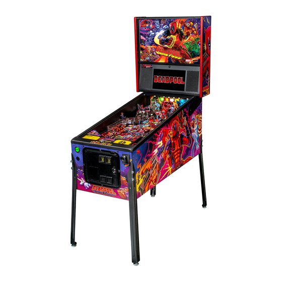
DEADPOOL
DEADPOOL PRO #500-55K1-01
1-800-KICKERS - parts.service@sternpinball.com
www.sternpinball.com - facebook.com/sternpinball
MANUAL #780-50K1-00
Advertisement
Table of Contents

Related Manuals for Stern Pinball Deadpool PRO


Summary of Contents for Stern Pinball Deadpool PRO
- Page 1 Stern Pinball machines are assembled in Elk Grove Village, Illinois, USA. Stern Pinball has inspected each game element to ensure it meets our quality standards. Each pinball machine has unique characteristics that make it a one-of-a-kind American made product. Each will have variations in appearance resulting from differences in the machine’s particular wood parts, individual printed art and mechanical assemblies.
-
Page 2: Table Of Contents
4.12 Ball Lock Opto Emitter ........30 4.13 Katana Ball Lock LED Board......31 4.14 3-Bank LED Board ..........31 4.15 Main Power Supply ..........31 4.16 Power Distribution Board ........32 4.17 Power Plug Wiring..........32 DEADPOOL PRO MANUAL 500-55K1-01 MARVEL.COM © MARVEL... -
Page 3: Setup And Moving
MOVE AND MANEUVER THE SETUP INSTRUCTIONS TOOLS REQUIRED GAME. USE PROPER MOVING EQUIPMENT EXTREME Your brand new Stern Pinball Machine is • 5/8” Socket Wrench CARE WHILE HANDLING. STERN carefully packed for safety and security. • Utility Knife PINBALL MACHINES... - Page 4 GLASS. TEMPERED GLASS IS SENSITIVE TO EXTREME TEMPERATURE SHIFTS AND CORNER NICKS, WHICH CAN CAUSE THE GLASS TO FAIL CATASTROPHI- CALLY. TAKE CARE TO STORE THE GLASS ON A SOFT, ROOM-TEMPERATURE SURFACE AND PREVENT THE CORNERS FROM BEING DAMAGED. DEADPOOL PRO MANUAL 500-55K1-01 MARVEL.COM © MARVEL...
- Page 5 Play game: Check for satisfactory operation and adjust game volume (push the Red Buttons inside the Coin Door). If desired, perform any game diagnostics, game adjust- ments, and pricing settings at this time. DEADPOOL PRO MANUAL 500-55K1-01 MARVEL.COM © MARVEL...
-
Page 6: Adjustments Menu
SELECT button or escape at any time. to choose options and the [<] [>] buttons to cycle through Press [>]. Go to the ADJ icon. Press SELECT. available settings. DEADPOOL PRO MANUAL 500-55K1-01 MARVEL.COM © MARVEL... -
Page 7: Transporting The Game
Stand the game up on its back. Remove the front two legs. 10. Secure all loose parts and trans- port with a hand truck in the upright position. DEADPOOL PRO MANUAL 500-55K1-01 MARVEL.COM © MARVEL... -
Page 8: Maintenance
Flipper Base Plate Kit Left 515-6617-01 proper operation. Flipper Rebuild Kit Right 500-6307-00 • Check for proper adjustment of the plumb bob tilt. Flipper Base Plate Kit Right 515-6617-00 • Play game: Check for satisfactory operation. DEADPOOL PRO MANUAL 500-55K1-01 MARVEL.COM © MARVEL... -
Page 9: Spike System And Node Guide
48V system power. SPIKE standard I/O nodes are low-power nodes that read switch inputs and output to A Stern Pinball machine based on the SPIKE system will have at standard-brightness LEDs. Standard I/O nodes use the node bus... -
Page 10: Spike Node Programming
Other optical switches connect directly to the Spike node board. System Protections CAUTION: Unless explicitly directed by an Authorized Stern Re- pair technician, perform ALL work on your pinball machine with the power disabled! DEADPOOL PRO MANUAL 500-55K1-01 MARVEL.COM © MARVEL... -
Page 11: Light, Switch, And Driver Reference
Trough Serial Opto Receiver Extension Playfield 520-7001-00 LED Lower Board Playfield 520-8045-00 755-7512-K1 LED Right Board Playfield 520-8047-00 Node 9 OFF-OFF-ON-OFF Playfield 48V Core-Driver Node Playfield 520-7017-72 LED Left Board Playfield 520-8046-00 LED Upper Board Playfield 520-8048-00 DEADPOOL PRO MANUAL 500-55K1-01 MARVEL.COM © MARVEL... -
Page 12: Driver Reference
GRY BRN Playfield Coil - 32-1250 9-DR-6 090-5060-01-ND Coin Meter Cabinet Digital Out 1-DR-2 500-9946-00 Ticket Meter Cabinet Digital Out 1-DR-3 500-9946-00 Ticket Dispenser CN11 Cabinet Digital Out 1-DR-4 Continued on next page... DEADPOOL PRO MANUAL 500-55K1-01 MARVEL.COM © MARVEL... - Page 13 SPIKE SYSTEM AND NODE GUIDE DRIVER REFERENCE CONTINUED Figure 3.2.1. Playfield driver locations (top view). DEADPOOL PRO MANUAL 500-55K1-01 MARVEL.COM © MARVEL...
-
Page 14: Switch Reference
8-SW-13 515-0215-00 tx 515-0215-01 rx Lower Inside Loop CN12 WHT GRN BLK RED Playfield Rollover 8-SW-12 500-9935-03 Hell House Eject CN12 WHT RED BLK RED Playfield Micro 8-SW-9 180-5209-00 Continued on next page... DEADPOOL PRO MANUAL 500-55K1-01 MARVEL.COM © MARVEL... - Page 15 Leaf 1-SW-2 180-5218-00 Start Button BLK WHT Cabinet Micro 1-SW-11 180-5174-00 Tournament Start GRY WHT BLK WHT Cabinet Micro 1-SW-12 180-5174-00 Button Left Coin PNK BRN Cabinet Micro 1-SW-16 Continued on next page... DEADPOOL PRO MANUAL 500-55K1-01 MARVEL.COM © MARVEL...
- Page 16 SPIKE SYSTEM AND NODE GUIDE SWITCH REFERENCE CONTINUED Figure 3.3.1. Playfield switch locations (top view). Continued on next page... DEADPOOL PRO MANUAL 500-55K1-01 MARVEL.COM © MARVEL...
- Page 17 DIP 4 CPU Node 0-SW-3 DIP 5 CPU Node 0-SW-4 DIP 6 CPU Node 0-SW-5 DIP 7 CPU Node 0-SW-6 DIP 8 CPU Node 0-SW-7 Service Select CN25 LGN GRY Coin Door 0-SW-8 180-5192-04 DEADPOOL PRO MANUAL 500-55K1-01 MARVEL.COM © MARVEL...
-
Page 18: Light Reference
Left Orbit Arrow-G GRN ORG 1/2/3 RED Playfield Feature 9-LP-24 520-5333-00 Left Orbit Arrow-B BLU ORG 1/2/3 RED Playfield Feature 9-LP-25 520-5333-00 Left Katana 1 LED2 Playfield Feature White 9-LP-9 520-8046-00 Continued on next page... DEADPOOL PRO MANUAL 500-55K1-01 MARVEL.COM © MARVEL... - Page 19 SPIKE SYSTEM AND NODE GUIDE LIGHT REFERENCE CONTINUED Figure 3.4.1. Playfield light locations (top view). Continued on next page... DEADPOOL PRO MANUAL 500-55K1-01 MARVEL.COM © MARVEL...
- Page 20 8-LP-43 520-8047-00 Right Orbit Arrow-R LED21 - Playfield Feature 8-LP-44 520-8047-00 Right Orbit Arrow-G LED21 - Playfield Feature 8-LP-45 520-8047-00 100 Right Orbit Arrow-B LED21 - Playfield Feature 8-LP-46 520-8047-00 Continued on next page... DEADPOOL PRO MANUAL 500-55K1-01 MARVEL.COM © MARVEL...
- Page 21 150 Coin Door GI YEL-WHT Coin Door G.I. White 1-LP-1 112-5033-08 151 Bottom GI CN15 5 WHT BLK 1 YEL BLK Playfield G.I. White 8-LP-0 112-5034-08 (WHT) 112-5034-02 (RED) 112-5034-08F (Slingshots) Continued on next page... DEADPOOL PRO MANUAL 500-55K1-01 MARVEL.COM © MARVEL...
-
Page 22: Motor Reference
Control 1A x-LP-2 Control 2A L/Low=Lamp On H/High=Lamp Off MOTOR B Coast Brake Brake Dir. 1 Dir. 2 x-LP-3 Enable B x-LP-4 Control 1B x-LP-5 Control 2B x=Node # L/Low=Lamp On H/High=Lamp Off DEADPOOL PRO MANUAL 500-55K1-01 MARVEL.COM © MARVEL... -
Page 23: Electronic Pinouts And Schematics
Node bus receive Node bus receive activity CN25 12-Pin .100” Header Dedicated switch inputs - service, volume Status System status Constant double blink - game switches software running Netstat Network status Communication bridge activity DEADPOOL PRO MANUAL 500-55K1-01 MARVEL.COM © MARVEL... - Page 24 Canada 2 Door Service Switches to function correctly. China Croatia Denmark Finland France Germany Greece Italy Japan Middle East Netherlands New Zealand Norway Portugal Russia S. Africa Spain Sweden Switzerland Taiwan United Kingdom DEADPOOL PRO MANUAL 500-55K1-01 MARVEL.COM © MARVEL...
-
Page 25: Cabinet Node 1
Shaker Motor (+) .100" 10-Pin Header dual Ground Shaker Motor (+) row. Coin 5 Electronic Coin Mech *Varies by country model Coin 6 Coin Enable/Inhibit (+) Coin 1 Coin 2 Coin 3 Coin 4 DEADPOOL PRO MANUAL 500-55K1-01 MARVEL.COM © MARVEL... -
Page 26: Lower Playfield 48V Driver Pinout Node 8
GRY-BLU Node Extension Bus 8-SW-31 Switch GRY-GRN VIO-BLK 8-SW-16 Switch GRY-YEL DOUT VIO-BRN Ground BLK-GRN VIO-RED Ground BLK-GRN VIO-ORG Ground BLK-GRN .100" 6-Pin Header, Ground Node Extension Bus VIO-BLK DOUT VIO-BRN VIO-RED VIO-ORG DEADPOOL PRO MANUAL 500-55K1-01 MARVEL.COM © MARVEL... - Page 27 .100" 6-Pin Header, Ground 9-SW-30 Switch GRY-RED Node Extension Bus 9-SW-31 Switch GRY-ORG DOUT 9-SW-16 Switch GRY-YEL Ground BLK-BLU Ground BLK-BLU Ground BLK-BLU .100" 6-Pin Header, Ground Node Extension Bus VIO-BLK DOUT VIO-BRN VIO-RED VIO-ORG DEADPOOL PRO MANUAL 500-55K1-01 MARVEL.COM © MARVEL...
-
Page 28: Trough Serial Opto Receiver Extension 8A
+5 VDC IN LP-14 Light Return GRN-WHT LP-15 Light Return ORG-RED LP-16 Light Return ORG-YEL .100" 6-Pin Header Ground MISO Output Data VIO-BLK MOSI Input Data VIO-BRN SCK Serial Clock VIO-RED RCK Register Clock VIO-ORG DEADPOOL PRO MANUAL 500-55K1-01 MARVEL.COM © MARVEL... -
Page 29: Right Led Board 8C
SCK Serial Clock VIO-RED LP-28 Light Return GRN-YEL RCK Register Clock VIO-ORG LP-29 Light Return LP-30 Light Return GRN-BLU LP-31 Light Return GRN-VIO LP-32 Light Return LP-33 Light Return LP-34 Light Return LP-35 Light Return DEADPOOL PRO MANUAL 500-55K1-01 MARVEL.COM © MARVEL... -
Page 30: Right Led Board 9B
ORG-GRY LP-16 Light Return RED-YEL LP-17 Light Return GRN-YEL LP-18 Light Return BLU-YEL LP-19 Light Return ORG-WHT .100" 6-Pin Header Ground MISO Output Data MOSI Input Data SCK Serial Clock RCK Register Clock DEADPOOL PRO MANUAL 500-55K1-01 MARVEL.COM © MARVEL... -
Page 31: Katana Ball Lock Led Board
520-7092-00 DC Ground +48 V System Power +48 V System Power +48 V System Power Type Description Wire Color .100" 4-Pin Header +5 VDC LED 1 BLU-VIO LED 2 BLU-GRY LED 3 BLU-WHT DEADPOOL PRO MANUAL 500-55K1-01 MARVEL.COM © MARVEL... -
Page 32: Power Distribution Board
Type Part Number Pin:055-5331-00 +12VDC Current (18awg) 120V (North America) Slow Blow MDL 200-5000-05 220/240v (Europe, Australia, Slow Blow MDL 200-5000-01 CN7 .084 2-Pos +48 VDC to CPU Node Plug: 045-5200-02 Ground Pin:055-5033-08 DEADPOOL PRO MANUAL 500-55K1-01 MARVEL.COM © MARVEL... - Page 33 ELECTRONIC PINOUTS AND SCHEMATICS DEADPOOL PRO MANUAL 500-55K1-01 MARVEL.COM © MARVEL...
-
Page 34: Parts Reference
Figure 5.2.1. Rubber ring inner diameter sizing tool. Hold ring up to chart and read largest size on inside of ring. Dimensions are Inner Diameter (ID) unless otherwise noted as Outer Diameter (OD). DEADPOOL PRO MANUAL 500-55K1-01 MARVEL.COM © MARVEL... -
Page 35: Playfield Assemblies, Top
Left Wire Ramp 515-1923-00 Right Wire Ramp 830-8378-76 Colossus Plastic 830-8378-75 Wolverine Plastic 830-8378-73 Dazzler 830-8378-77 Domino 511-7801-47 Deadpool Hammock 511-1954-00 Lil Deadpool Bash Toy 515-1895-01 Spotlight Figure 5.3.1. Major playfield assemblies, Top locations. DEADPOOL PRO MANUAL 500-55K1-01 MARVEL.COM © MARVEL... -
Page 36: Playfield Assemblies, Bottom
Core-Driver Node Board 520-8045-00 LED Lower Board 520-8047-00 LED Right Board 520-8046-00 LED Left Board 520-8048-00 LED Upper Board 500-5329-03 Pivot Pin 535-5988-01 Edge Slide Bracket 535-6862-05 Rail Figure 5.4.1. Major playfield assemblies, Bottom locations. DEADPOOL PRO MANUAL 500-55K1-01 MARVEL.COM © MARVEL... -
Page 37: Backbox Parts
#6 Washer 355-5168-00-00 Nut: Lock w/ Cam 515-9842-00 Speaker Panel-LCD 515-9843-00 Speaker Plate 515-9845-00 Hinge, Speaker Panel, LCD 545-9877-00 LCD Window 545-9877-01 Spacer, Small - LCD Speaker Panel 626-5109-00 Speaker Foam - LCD Panel DEADPOOL PRO MANUAL 500-55K1-01 MARVEL.COM © MARVEL... -
Page 38: Cabinet Parts
Cabinet Node Board 545-5072-02 Grill - Speaker / Vent 820-78K1-XX Cabinet Decal Replacement Set, Speaker 031-5007-01 Speaker, Cabinet 8" Round, 4 ohm Panel Decal Not Included 545-5090-00 Cash Box - Plastic 535-5013-03 Cash Box Cover DEADPOOL PRO MANUAL 500-55K1-01 MARVEL.COM © MARVEL... -
Page 39: Ball Shooter Assembly
535-5067-02 Housing Assembly 266-5001-07 Compressed Spring (Long) - Orange FRONT MOLDING ASSEMBLY 242-5014-00 Washer 3/8 ID x 5/8 OD x 1/16 DEADPOOL PRO & PREMIUM / LE 515-6557-00 Rod Assembly 500-1144-K2-00 / 500-1144-K2-29 266-5010-00 Compressed Spring (Short) 270-5012-00 Retaining Ring, 3/8"... -
Page 40: Ball Trough Assembly
SHRINK TUBING 1/8" .42 FT. 515-5340-01 ARM & TIP ASSEMBLY 036-5611-11-F5 CABLE TROUGH OPTOS 270-5002-00 RETAINING RING - 1/4 DIA 515-5338-00 PLUNGER & LINK ASSEMBLY 266-5020-00 COMP SPRING CONICAL 036-5604-00 4" GENERIC JUMPER DEADPOOL PRO MANUAL 500-55K1-01 MARVEL.COM © MARVEL... -
Page 41: Flipper Assembly, Left
FLIPPER REBUILD KIT, LEFT 500-6307-00 FLIPPER REBUILD KIT, RIGHT * Refer to game rubber chart for flipper * Refer to game rubber chart for flipper rubber color and part number. rubber color and part number. DEADPOOL PRO MANUAL 500-55K1-01 MARVEL.COM © MARVEL... -
Page 42: Pop Bumper Assembly
COIL BRACKET POP BUMPER ASSY 545-5607-00 BUMPER SKIRT 18 545-5609-00 FIBER YOKE 266-5048-00 BUMPER SKIRT COMP SPRING 19 535-7346-00 METAL YOKE 545-5195-00 BUMPER BASE 20 237-5957-00 #6-32 x 1-3/16" SPIRAL FIN SHANK SCREW DEADPOOL PRO MANUAL 500-55K1-01 MARVEL.COM © MARVEL... -
Page 43: Bash Pivot Assembly
WASHER, 1/4 X 7/16 X 1/32 180-5209-00 SUB MINIATURE SWITCH - SIM. ROLLER 270-5002-00 RETAINING RING - 1/4" 535-6539-00 SWITCH BODY PROTECT PLATE 036-6274-18-K2 CABLE, BASHPOOL TARGET 237-5937-02 SCREW, 2-56 X 1/2" HWH MS 036-5541-00 GENERIC COIL CABLE DEADPOOL PRO MANUAL 500-55K1-01 MARVEL.COM © MARVEL... -
Page 44: Katana Trough Assembly
PARTS REFERENCE KATANA TROUGH ASSEMBLY DEADPOOL PRO / LE / PREMIUM 511-1914-00 5.18 KATANA TROUGH ASSEMBLY 5.19 KATANA LOCK DOWN POST ASSEMBLY 511-1914-00 KATANA LOCK DOWN POST ASSEMBLY 500-6752-02 DEADPOOL PRO / LE / PREMIUM 500-6752-02 QTY. ITEM NO. PART NUMBER DESCRIPTION QTY. -
Page 45: 3-Bank Drop Target W/ Trip Assembly
PARTS REFERENCE 3-BANK DROP TARGET W/ TRIP ASSEMBLY 5.20 3-BANK DROP TARGET W/ TRIP ASSEMBLY DEADPOOL PRO / LE / PREMIUM 500-1083-03-00 500-1083-03-00 QTY. W/ RIGHT ANGLE CONN SECTION A-A ET W/ TRIP Part Number Description 090-5034-ND COIL 25-1240 - NO DIODE... -
Page 46: Electric Gate Assembly
HAT - TRIMMED - RED SB 520-7000-00 SINGLE FLASH LED BOARD 036-6243-10 CABLE, GENERIC LAMP 2-PIN 830-8378-68 PLASTIC #68, TRUCK ROOF, DEAD- POOL PRO 237-6154-01 SCREW, 4-40 X 3/8" PTH MS - BLACK 240-5303-00 4-40 NYLON LOCK NUT DEADPOOL PRO MANUAL 500-55K1-01 MARVEL.COM © MARVEL... -
Page 47: Left Ramp Assembly
HEX SPACER - 1 3/8 " 232-5200-00 SCREW, 6-32 X 1/4" PPH SEMS 232-5201-00 SCREW, 6-32 X 3/8" PPH MS SEMS 511-7801-47 ASSEMBLY, PLASTIC #47, DEADPOOL PRO 830-8378-46 PLASTIC #46, REAR METAL RAMP COVER, 242-5001-00 #6 WASHER DEADPOOL PRO 242-5002-00 #4 FLAT WASHER - 5/16"... -
Page 48: Ball Guide #3 & Spinner Assembly
DEADPOOL PRO / LE / PREMIUM 511-7800-28 PARTS REFERENCE 5.27 BALL GUIDE #8 & OPTO 5.25 BALL GUIDE #3 & SPINNER ASSEMBLY ASSEMBLY ITEM NO. PART NUMBER DESCRIPTION QTY. 511-7800-23 511-7800-28 535-1461-28 BALL GUIDE #8, GUY 626-5067-00 RUBBER BUMPER - BLUE - FASTENED... -
Page 49: Back Panel Diffuser & Led
PARTS REFERENCE 5.29 BACK PANEL DIFFUSER & LED 5.30 BACK PANEL ASSEMBLY BACK PANEL DIFFUSER & LED ASSEMBLY 511-7949-00 500-1027-03 BACK PANEL ASSEMBLY DEADPOOL PRO / LE / PREMIUM DEADPOOL PRO 511-7949-00 500-1027-03 ITEM NO. PART NUMBER DESCRIPTION QTY. 525-9707-02... -
Page 50: Specifications
Nominal Line Power Current rating for your line voltage. For example, a 15A 120V household circuit, 15/3 A (nominal current) = 5 games maximum. DEADPOOL PRO MANUAL 500-55K1-01 MARVEL.COM © MARVEL... -
Page 51: Warranty
Stern Pinball Inc (‘SELLER’) warrants only to the initial purchaser of its consciousness or convulsions that can lead to injury from falling down or products that the items listed below are free from defects in material striking nearby objects. - Page 52 1-800-KICKERS DEADPOOL PRO #500-55K1-01 MANUAL #780-50K1-00 PARTS.SERVICE@STERNPINBALL.COM WWW.STERNPINBALL.COM *780-50K1-00* FACEBOOK.COM/STERNPINBALL...
Need help?
Do you have a question about the Deadpool PRO and is the answer not in the manual?
Questions and answers
How do I f d the total plays on my Deadpool pinball game?
To find the total plays on your Stern Pinball Deadpool PRO, check the game audits. Navigate to the game’s menu system, locate the audits section, and look for total plays or a similar statistic.
This answer is automatically generated