Table of Contents
Advertisement
Quick Links
SERVICE AND OPERATION MANUAL
WARNING
IMPORTANT HEALTH WARNING: PHOTOSENSITIVE SEIZURES - A very small percentage of people may experience a seizure when exposed to certain visual images,
including flashing lights or patterns. Even people with no history of seizures of epilepsy may have an undiagnosed condition that can cause "photosensitive epileptic
seizures" due to certain visual images, flashing lights or patterns. Symptoms can include lightheadedness, altered vision, eye or face twitching, jerking or shaking of arms or
legs, disorientation, confusion, momentary loss of awareness, and loss of consciousness or convulsions that can lead to injury from falling down or striking nearby objects.
IMMEDIATELY STOP PLAYING AND CONSULT A DOCTOR IF YOU EXPERIENCE ANY OF THESE SYMPTOMS.
ATTENTION! IMPORTANT WARRANTY INFORMATION
The electronics system, node network architecture, mechanical devices and associated software control systems in this pinball machine are designed to work with genuine
Stern Pinball accessories and devices.
Installation of non-authorized accessories, lamps, LED's, motors or other devices or modification of electro-mechanical devices may damage the system and will void your
warranty.
Stern Pinball machines are assembled in Elk Grove Village, Illinois, USA. Stern Pinball has inspected each game element to ensure it meets our quality standards.
Each pinball machine has unique characteristics that make it a one-of-a-kind American made product. Each will have variations in appearance resulting from differences
in the machine's particular wood parts, individual printed art and mechanical assemblies. No playfield is perfectly flat and varies depending on the season. Game play will
result in playfield dimpling as the harder steel ball contacts the wood and coating; over time multiple dimples will blend to make them less noticeable. Normal plastic insert
crazing (tiny stress cracks) and ghosting (small cloudy areas around insert edges) are often seen in pinball machines, due to a combination of plastic mold stress, pushing of
inserts into purposely undersized holes, and heating and breaking of inserts' plastic "skin" when the playfield is sanded.
© MARVEL
Games configured for North America operate on 60 cycle electricity only. These games will not operate in countries with 50 cycle electricity (Europe, UK, Australia).
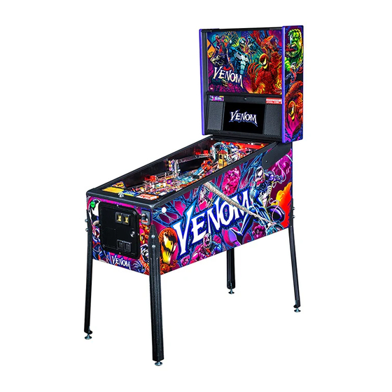
VENOM
VENOM PRO #500-55U1-01
1-800-KICKERS - parts.service@sternpinball.com
www.sternpinball.com - facebook.com/sternpinball
MANUAL #780-50U1-00
Advertisement
Table of Contents

Subscribe to Our Youtube Channel
Related Manuals for Stern Pinball VENOM PRO


Summary of Contents for Stern Pinball VENOM PRO
- Page 1 Stern Pinball machines are assembled in Elk Grove Village, Illinois, USA. Stern Pinball has inspected each game element to ensure it meets our quality standards. Each pinball machine has unique characteristics that make it a one-of-a-kind American made product. Each will have variations in appearance resulting from differences in the machine’s particular wood parts, individual printed art and mechanical assemblies.
-
Page 2: Table Of Contents
Warranty ............. 61 Playfield Assemblies, Bottom ......40 Warnings, Compliance, and Legal Notices ..61 Backbox Parts............ 41 Stern Pinball End User License Agreement ..62 Speaker Panel Parts .......... 41 Cabinet Parts ............. 42 VENOM PRO MANUAL 500-55U1-01 © MARVEL... -
Page 3: Setup And Moving
MOVE AND MANEUVER THE SETUP INSTRUCTIONS TOOLS REQUIRED GAME. USE PROPER MOVING EQUIPMENT EXTREME Your brand new Stern Pinball Machine is • 5/8” Socket Wrench CARE WHILE HANDLING. STERN carefully packed for safety and security. • Utility Knife PINBALL MACHINES... - Page 4 GLASS. TEMPERED GLASS IS SENSITIVE TO EXTREME TEMPERATURE SHIFTS AND CORNER NICKS, WHICH CAN CAUSE THE GLASS TO FAIL CATASTROPHI- CALLY. TAKE CARE TO STORE THE GLASS ON A SOFT, ROOM-TEMPERATURE SURFACE AND PREVENT THE CORNERS FROM BEING DAMAGED. VENOM PRO MANUAL 500-55U1-01 © MARVEL...
- Page 5 Play game: Check for satisfactory operation and adjust game volume (push the Red Buttons inside the Coin Door). If desired, perform any game diagnostics, game adjust- ments, and pricing settings at this time. ON/OFF Switch VENOM PRO MANUAL 500-55U1-01 © MARVEL...
-
Page 6: Adjustments Menu
SELECT button or escape at any time. to choose options and the [<] [>] buttons to cycle through Press [>]. Go to the ADJ icon. Press SELECT. available settings. VENOM PRO MANUAL 500-55U1-01 © MARVEL... -
Page 7: Transporting The Game
Stand the game up on its back. Remove the front two legs. 10. Secure all loose parts and trans- port with a hand truck in the upright position. VENOM PRO MANUAL 500-55U1-01 © MARVEL... -
Page 8: Maintenance
• Check all settings (refer to manual for factory settings). • Check coin door: With door closed, insert coins to verify proper operation. • Check for proper adjustment of the plumb bob tilt. • Play game: Check for satisfactory operation. VENOM PRO MANUAL 500-55U1-01 © MARVEL... -
Page 9: Spike System And Node Guide
48V system power. SPIKE standard I/O nodes are low-power nodes that read switch inputs and output to A Stern Pinball machine based on the SPIKE system will have at standard-brightness LEDs. Standard I/O nodes use the node bus... -
Page 10: Spike Node Programming
Other optical switches connect directly to the Spike node board. CAUTION: Unless explicitly directed by an Authorized Stern Repair technician, perform ALL work on your pinball machine with the power disabled! VENOM PRO MANUAL 500-55U1-01 © MARVEL... -
Page 11: Light, Switch, And Driver Reference
520-8581-00 PCB 3LED Playfield (Top of Playfield) 520-8581-00 PCB Right Upper Playfield 520-8579-00 PCB Host Sign Playfield (Top of Playfield) 520-8583-00 Node 12 ON-OFF-OFF-OFF Core - Driver Node (Topper Optional) Topper 520-1057-00 / 520-7017-72 VENOM PRO MANUAL 500-55U1-01 © MARVEL... -
Page 12: Driver Reference
Playfield Coil - 23-800 9-DR-4 090-5001-ND 33 Coin Meter Cabinet Digital Out 1-DR-2 500-9946-00 34 Ticket Meter Cabinet Digital Out 1-DR-3 500-9946-00 35 Ticket Dispenser CN11 Cabinet Digital Out 1-DR-4 Continued on next page... VENOM PRO MANUAL 500-55U1-01 © MARVEL... - Page 13 LIGHT, SWITCH, AND DRIVER REFERENCE DRIVER REFERENCE CONTINUED Figure 3.2.1. Playfield driver locations (top view). VENOM PRO MANUAL 500-55U1-01 © MARVEL...
-
Page 14: Switch Reference
520-5378-00 rx Right Target CN11 LGN GRY 11/12 BLK ORG Playfield Leaf, Target 8-SW-22 515-9784-00-00 Right Lock 1 Opto CN13 PNK GRN BLK BRN Playfield Opto 8-SW-3 520-5377-00 tx 520-5378-00 rx Continued on next page... VENOM PRO MANUAL 500-55U1-01 © MARVEL... - Page 15 VUK Opto CN13 PNK VIO BLK BRN Playfield Opto 9-SW-5 515-0223-00 tx 515-0223-01 rx Subway Left Opto CN13 PNK WHT 10 BLK BRN Playfield Opto 9-SW-7 515-0223-00 tx 515-0223-01 rx Continued on next page... VENOM PRO MANUAL 500-55U1-01 © MARVEL...
- Page 16 C18 Headphone Kit Cable CPU Node 0-SW-17 Detect C19 Volume Encoder 1 DRAIN CPU Node 0-SW-18 C20 Volume Encoder 2 DRAIN CPU Node 0-SW-19 C24 Coin Door Interlock GRY RED Backbox 0-SW-23 Continued on next page... VENOM PRO MANUAL 500-55U1-01 © MARVEL...
- Page 17 LIGHT, SWITCH, AND DRIVER REFERENCE SWITCH REFERENCE CONTINUED Figure 3.3.1. Playfield switch locations (top view). VENOM PRO MANUAL 500-55U1-01 © MARVEL...
-
Page 18: Light Reference
LED8 Playfield Feature RGB 8-LP-70 520-8575-00 Agony 3-B LED8 Playfield Feature RGB 8-LP-71 520-8575-00 Phage-R LED12 - Playfield Feature RGB 8-LP-81 520-8575-00 Phage-G LED12 - Playfield Feature RGB 8-LP-82 520-8575-00 Continued on next page... VENOM PRO MANUAL 500-55U1-01 © MARVEL... - Page 19 LED17 - Playfield Feature RGB 8-LP-26 520-8576-00 BRN GRN 1/2/3/4 Playfield Feature White 8-LP-12 520-7011-00 BRN VIO 1/2/3/4 Playfield Feature White 8-LP-13 520-7011-00 BRN GRY 1/2/3/4 Playfield Feature White 8-LP-14 520-7011-00 Continued on next page... VENOM PRO MANUAL 500-55U1-01 © MARVEL...
- Page 20 RGB 9-LP-74 520-8579-00 Left Loop-G LED15 - Playfield Feature RGB 9-LP-75 520-8579-00 Left Loop-B LED15 - Playfield Feature RGB 9-LP-76 520-8579-00 Left Loop Web LED5 Playfield Feature White 9-LP-52 520-8579-00 Continued on next page... VENOM PRO MANUAL 500-55U1-01 © MARVEL...
- Page 21 Playfield Feature RGB 9-LP-63 520-8579-00 Right Orbit Lock-B LED11 - Playfield Feature RGB 9-LP-64 520-8579-00 Top Lane Left (2x) ORG RED 1/2/3/4 Playfield Feature White 9-LP-25 520-5307-00 520-7000- 00(Back Pnl) Continued on next page... VENOM PRO MANUAL 500-55U1-01 © MARVEL...
- Page 22 112-5034-08F 520-7000- 00(Bot.Arch) Left GI-RED (x7) CN15 6 RED BLK YEL RED Playfield G.I. 8-LP-1 112-5034-02F Left GI-2 (x5) CN15 7 BLU BLK YEL BLU Playfield G.I. White 8-LP-2 112-5034-08F Continued on next page... VENOM PRO MANUAL 500-55U1-01 © MARVEL...
- Page 23 Up Right Flash CN14 3 BRN GRY 7/8 Playfield Flash White 9-LP-6 520-7000-00 Ravencroft Flash-WHT YEL WHT 1/2/3/4 Playfield Flash White 9-LP-38 520-7000-00 Ravencroft Flash-RED YEL VIO 1/2/3/4 Playfield Flash 9-LP-39 520-8457-00 Continued on next page... VENOM PRO MANUAL 500-55U1-01 © MARVEL...
- Page 24 LIGHT, SWITCH, AND DRIVER REFERENCE LIGHT REFERENCE CONTINUED Figure 3.4.1. Playfield light locations (top view). VENOM PRO MANUAL 500-55U1-01 © MARVEL...
-
Page 25: Electronic Pinouts And Schematics
OFF: Processor not running, call tech support. μSD ACT Activity indicator Should blink rapidly when reading or writing to for micro SD Card micro SD card. Netbridge Status Red Should blink once every ~1/2 second. VENOM PRO MANUAL 500-55U1-01 © MARVEL... - Page 26 CN10 and CN12 connected for the Coin Canada 2 Door Service Switches to function correctly. China Croatia Denmark Finland France Germany Greece Italy Japan Middle East Netherlands New Zealand Norway Portugal Russia S. Africa Spain Sweden Switzerland Taiwan United Kingdom VENOM PRO MANUAL 500-55U1-01 © MARVEL...
- Page 27 ELECTRONIC PINOUTS AND SCHEMATICS USA & INTERNATIONAL (NON-EURO) STANDARD PRICING SELECT TABLE VENOM PRO MANUAL 500-55U1-01 © MARVEL...
- Page 28 ITALY 2 1/1.00 3/2.00 755-5401-08- Pos. Default Highlighted NETHERLANDS 755-5401-03- Euro 3 Pos. Default Highlighted 755-5401-01- PORTUGAL Pos. Default Highlighted SPAIN 755-5401-08- Euro 8 = Factory Default = Not Shown on Coin Card HIGHLIGHTED HIGHLIGHTED VENOM PRO MANUAL 500-55U1-01 © MARVEL...
-
Page 29: Cabinet Node 1
Shaker Motor (-) Shaker Motor (-) Electronic Coin Mech Shaker Motor Coin 5 Shaker Motor (+) Coin 6 Shaker Motor (+) Coin Enable/Inhibit (+) Coin 1 *Varies by country model Coin 2 Coin 3 Coin 4 VENOM PRO MANUAL 500-55U1-01 © MARVEL... -
Page 30: Lower Playfield 48V Driver Pinout Node 8
.100" 6-Pin Header, Ground 8-SW-31 Switch GRY-GRN Node Extension Bus VIO-BLK 8-SW-16 Switch GRY-YEL DOUT VIO-BRN Ground BLK-GRN VIO-RED Ground BLK-GRN VIO-ORG Ground BLK-GRN .100" 6-Pin Header, Ground Node Extension Bus VIO-BLK DOUT VIO-BRN VIO-RED VIO-ORG VENOM PRO MANUAL 500-55U1-01 © MARVEL... - Page 31 9-SW-30 Switch GRY-RED .100" 6-Pin Header, Ground 9-SW-31 Switch GRY-ORG Node Extension Bus 9-SW-16 Switch GRY-YEL DOUT Ground BLK-BLU Ground BLK-BLU Ground BLK-BLU .100" 6-Pin Header, Ground Node Extension Bus VIO-BLK DOUT VIO-BRN VIO-RED VIO-ORG VENOM PRO MANUAL 500-55U1-01 © MARVEL...
-
Page 32: Center Mid Led Board 8B
MOSI Input Data VIO-BRN LED 35 YEL-RED SCK Serial Clock VIO-RED LED 34 YEL-ORG RCK Register Clock VIO-ORG LED 33 YEL-GRN LED 32 YEL-BLU +5 VDC IN LED 31 YEL-VIO LED 30 YEL-GRY LED 29 VENOM PRO MANUAL 500-55U1-01 © MARVEL... -
Page 33: 3-Led Board 8B1
+5 VDC IN Type Pin Description Wire Color .100" 6-Pin Header Ground .100" 5-Pin Header MISO Output Data LED1-R RED-BRN MOSI Input Data LED1-G GRN-BRN SCK Serial Clock LED1-B BLU-BRN RCK Register Clock LED2 RED-WHT VENOM PRO MANUAL 500-55U1-01 © MARVEL... -
Page 34: Center Left Led Board 9A
ORG-BLU .100" 5-Pin Header LED 19 ORG-VIO LED 20 ORG-GRY LP-1 Light Return ORG-GRY LED 21 ORG-WHT LP-2 Light Return ORG-WHT LED 22 ORG-BLK LP-3 Light Return ORG-BLK LED 23 YEL-WHT LED 24 YEL-VIO VENOM PRO MANUAL 500-55U1-01 © MARVEL... -
Page 35: Right Upper Led Board 9B
RCK Register Clock .100" 12-Pin Header +5 VDC +5 VDC +5 VDC LED 17 RED-BRN LED 18 RED-ORG LED 19 RED-YEL LED 20 RED-GRN LED 21 RED-BLU LED 22 RED-VIO LED 23 RED-GRY LED 24 RED=WHT VENOM PRO MANUAL 500-55U1-01 © MARVEL... -
Page 36: Trough Serial Opto Receiver 8A
+48 V System Power SCK Serial Clock +48 V System Power RCK Register Clock +48 V System Power 4.18 TROUGH SERIAL OPTO TRANSMITTER 520-5344-00 Type Description Wire Color .100" 3-Pin Header Ground +5 VDC IN VENOM PRO MANUAL 500-55U1-01 © MARVEL... -
Page 37: Power Distribution Board
Type Part Number +12VDC (18awg) Current 120V (North America) Slow Blow 30G 200-5000-05 220/240v (Europe, Australia, Slow Blow 5 x 200-5003-00 CN7 .084 2-Pos +48 VDC to Topper Node 20mm Plug: 045-5200-02 Ground Pin:055-5033-08 VENOM PRO MANUAL 500-55U1-01 © MARVEL... -
Page 38: Parts Reference
Figure 5.2.1. Rubber ring inner diameter sizing tool. Hold ring up to Figure 5.1.1. Rubber o-ring part locations chart and read largest size on inside of ring. Dimensions are Inner Diameter (ID) unless otherwise noted as Outer Diameter (OD). VENOM PRO MANUAL 500-55U1-01 © MARVEL... -
Page 39: Playfield Assemblies, Top
Top Post Pin Mech Assembly 511-5326-01 Ball Guide with Gate Assembly, Pro 511-7304-00 Left Ramp Assembly 500-2661-00 CARNAGE Ratchet Assembly 500-1199-00 Center Ramp Assembly 510-5805-18 Riveted Plastic -18 515-1935-00 Newton Ball Figure 5.3.1. Major playfield assemblies, Top locations. VENOM PRO MANUAL 500-55U1-01 © MARVEL... -
Page 40: Playfield Assemblies, Bottom
Conical Compression Spring 511-5314-01 Pro VUK Trough Assembly 511-5329-00 VUK Coil Bracket Assembly 511-7621-00 Support Rail Assembly 500-5329-03 Pivot Bracket Assembly 535-5988-01 Edge Slide Bracket 535-2288-00 Backpanel Handle Figure 5.4.1. Major playfield assemblies, Bottom locations. VENOM PRO MANUAL 500-55U1-01 © MARVEL... -
Page 41: Backbox Parts
355-5168-00-00 Nut: Lock w/ Cam 515-9842-00 Speaker Panel - LCD 515-9843-00 Speaker Plate 515-9845-00 Hinge, Speaker Panel, LCD 545-9877-00 LCD Window 545-9877-01 Spacer, Small - LCD Speaker Panel 626-5109-00 Speaker Foam - LCD Panel VENOM PRO MANUAL 500-55U1-01 © MARVEL... -
Page 42: Cabinet Parts
Leg Assembly - Wrinkle Black 535-5027-01 Plunger Support Plate, Notched 516-0007-00 Tilt Assembly 500-1169-38 Flipper Button Assembly (White) 820-76U1-03 Decal, Cabinet Left, Venom Pro 500-1060-44-LED Start Button 820-76U1-04 Decal, Cabinet Right, Venom Pro 501-5018-173 Coin Door 2-Chute No Emboss 820-76U1-05... -
Page 43: Ball Shooter Assembly
NYLINER, 1/4" SHAFT, 4L1-FF 237-5937-02 SCREW, 2-56 X 1/2" HWH MS 535-6539-00 SWITCH BODY PROTECT PLATE 180-5157-01 SHOOTER SWITCH - SHORT ARM 545-6268-00 FISCHE PAPER 535-0762-00 COIL BRACKET-AUTOPLUNGER 515-6304-03 PLUNGER / LINK ASSEMBLY 545-0762-00 FISCHE PAPER: AUTO-LAUNCHER VENOM PRO MANUAL 500-55U1-01 © MARVEL... -
Page 44: Ball Trough Assembly
605-5006-00 SHRINK TUBING 1/8" .42 FT. 515-5340-01 ARM & TIP ASSEMBLY 036-5611-11-F5 CABLE TROUGH OPTOS 270-5002-00 RETAINING RING - 1/4 DIA 515-5338-00 PLUNGER & LINK ASSEMBLY 266-5020-00 COMP SPRING CONICAL 036-5604-00 4" GENERIC JUMPER VENOM PRO MANUAL 500-55U1-01 © MARVEL... -
Page 45: Flipper Assembly, Left
RUBBER BUMPER 545-5428-00 RUBBER BUMPER 090-5062-ND 23-1500 FIRST "X" IN PART NUMBER 090-5030-ND 23-1100 SECOND "X" IN PART NUMB 090-5020-30-ND 23-900 090-5032-ND 22-1080 090-5020-20-ND 22-900 COIL - X PART NUMBER COIL WINDING COIL TABLE VENOM PRO MANUAL 500-55U1-01 © MARVEL... -
Page 46: Bottom Arch Assembly
PLASTIC SPACER #4 SCREW, 3/16" OD - 9/32" LENGTH 240-5303-00 4-40 NYLON LOCK NUT 545-5411-00 COIL SLEEVE 820-5422-00 WARNING DECAL, BOTTOM ARCH, QR READER 546-5008-00 LOCK LINKAGE NOTE: "XX" IN ALL PART NUMBERS REFER TO GAME CODE. VENOM PRO MANUAL 500-55U1-01 © MARVEL... -
Page 47: Ball Lock Cover Assembly, Left
511-0016-00 SINGLE FLASH LED BOARD W/ CABLE 520-8581-00 LOCK 3 LED: VENOM 535-2696-03 BALL LOCK COVER 535-2847-00 RIGHT LOCK BB BRACKET: VENOM 550-5031-02 MINI MARS W/ EARS - RED SB 830-1159-22 PLASTIC: VENOM -22 VENOM PRO MANUAL 500-55U1-01 © MARVEL... -
Page 48: Ratchet Mech Assembly
535-2821-00 CARRIAGE TOP PLATE: VENOM 535-2871-00 CARRIAGE BOTTOM PLATE: VENOM 544-1319-00 RATCHET SLED: VENOM 544-1329-00 RATCHET PAWL: VENOM 545-6853-00 CARNAGE 626-5078-00 3/16" FOAM PAD 242-5082-00 11/64" ID X 3/8" OD X .031 FIBER WASHER VENOM PRO MANUAL 500-55U1-01 © MARVEL... -
Page 49: Ratchet Coil Assembly
511-2482-06 RATCHET AWAY SWITCH ASSEMBLY 530-2733-00 CARNAGE, BOTTOM RAIL: VENOM 515-2731-00 RATCHET - RIGHT PLATE: VENOM 530-2734-00 RATCHET TOP RAIL: VENOM 520-8541-00 SPINNER REFLECTICE OPTIC PCA 511-2482-00 CARNAGE CARRIER ASSEMBLY 830-1159-73 PLASTIC: VENOM -73 VENOM PRO MANUAL 500-55U1-01 © MARVEL... -
Page 50: Ratchet Bottom Plate Assembly
SPRING PIN 5/32D X 1/2" 530-5349-01 FLIPPER PLUNGER 546-2737-00 RATCHET COIL LINK: VENOM Part Number Description 180-5010-02 MICRO-SWITCH 237-5937-02 SCREW, 2-56 X 1/2" HWH MS 535-2735-00 RATCHET SWITCH BRACKET: VENOM 535-6539-00 SWITCH BODY PROTECT PLATE VENOM PRO MANUAL 500-55U1-01 © MARVEL... -
Page 51: Bell Tower Assembly
DECAL: VENOM -35B TOP REAR SWITCH 820-5471-36A DECAL: VENOM -36A 535-2844-00 WIRE, ROLLUNDER GATE: VENOM 820-5471-36B DECAL: VENOM -36B 535-6539-00 SWITCH BODY PROTECT PLATE 820-5471-36C DECAL: VENOM -36C 820-5471-36D DECAL: VENOM -36D 887-5002-00 BELL TOWER BELL VENOM PRO MANUAL 500-55U1-01 © MARVEL... -
Page 52: Top Post Assembly
PLATE, PIN MECH 535-5203-03 COIL RETAINING BRACKET 545-5076-01 COIL SLEEVE Part Number Description 000-5093-00 LOCTITE THREAD LOCK 425 "DARK BLUE CYANOACRYLATE" 232-5401-00 SCREW, 10-32 X 3/8 PPH SEMS 530-8051-00 PIN, PIN MECH 535-2814-00 PIN LINK VENOM PRO MANUAL 500-55U1-01 © MARVEL... -
Page 53: Vuk Trough Assembly
PRODUCTION RELEASE 820-7954-00 VENOM TROUGH LABEL DATE: 5/28/2023 5.36 VUK HOOD ASSEMBLY APPROVED & READY FOR PRODUCTION PARTS MUST BE RoHS COMPLIANT 511-2044-00 Part Number Description 515-2478-00 VUK HOOD: VENOM 820-5471-24 DECAL: VENOM -24 VENOM PRO MANUAL 500-55U1-01 © MARVEL... -
Page 54: Plastic 06 Assembly
HEX SPACER - 1" 520-7000-00 SINGLE FLASH LED BOARD 535-1305-01 BRACKET - PLASTIC MTG - 110° 550-5031-02 MINI MARS W/ EARS - RED SB 830-1159-06 PLASTIC: VENOM -06 830-1159-10 PLASTIC: VENOM -10 830-1159-41 PLASTIC: VENOM -41 VENOM PRO MANUAL 500-55U1-01 © MARVEL... -
Page 55: Plastic 21 Assembly
4-40 NYLON LOCK NUT 254-5000-09 NYLON SPACER - BLACK - 3/8 OD X .175 ID X 1/4" 520-7000-00 SINGLE FLASH LED BOARD 535-2693-38 BALL GUIDE: VENOM -38 535-2693-39 BALL GUIDE: VENOM -39 830-1159-51 PLASTICS: VENOM -51 VENOM PRO MANUAL 500-55U1-01 © MARVEL... -
Page 56: Plastic 54 Assembly
MINI POST - CLEAR 249-5001-01 RIVET - 1/8 X 3/16 - BLACK 830-1164-56 PLASTIC: VENOM -08 535-1305-00 BRACKET - PLASTIC MTG - 90° 535-1305-05 BRACKET - PLASTIC MTG - 100° 830-1164-69 PLASTIC: VENOM -69 VENOM PRO MANUAL 500-55U1-01 © MARVEL... -
Page 57: Left Loop Opto Receiver Assembly
OPTO BRKT - BIG SLOT PRODUCTION RELEASE DATE: 5/24/2023 APPROVED & READY FOR PRODUCTION 5.48 BALL GUIDE 22 ASSEMBLY PARTS MUST BE RoHS COMPLIANT 511-5965-22 Part Number Description 535-2693-22 BALL GUIDE: VENOM -22 820-5471-37 DECAL: VENOM -37 VENOM PRO MANUAL 500-55U1-01 © MARVEL... -
Page 58: Left Ramp Assembly
MINI MARS W/ EARS - RED SB 820-5471-28 DECAL: VENOM -28 Part Number Description 240-5303-00 4-40 NYLON LOCK NUT 511-5815-01 ASSEMBLY, MINI-OPTO RECEIVER & CABLE 1 535-2693-42 BALL GUIDE: VENOM -42 545-2746-00 OPTO SPACER VENOM PRO MANUAL 500-55U1-01 © MARVEL... -
Page 59: Center Ramp Assembly
254-5000-05 NYLON SPACER - BLACK - 3/8 OD X .175 ID X 1-1/4" 500-9988-00 TOP POST ASSEMBLY 511-5966-51 PLASTIC ASSEMBLY: VENOM -51 525-5929-01 BACK PANEL: VENOM PRO 535-2288-00 HANDLE, BACKPANEL 820-5471-31A DECAL: VENOM -31A 820-5471-31B DECAL: VENOM -31B 820-5471-32 DECAL: VENOM -32... -
Page 60: Specifications
Nominal Line Power Current rating for your line voltage. For example, a 15A 120V household circuit, 15/3 A (nominal current) = 5 games maximum. VENOM PRO MANUAL 500-55U1-01 © MARVEL... -
Page 61: Warranty
STERN PINBALL INC LIMITED WARRANTY disorientation, confusion, momentary loss of awareness, and loss of Stern Pinball Inc (‘SELLER’) warrants only to the initial purchaser of its consciousness or convulsions that can lead to injury from falling down or striking nearby objects. -
Page 62: Stern Pinball End User License Agreement
BY USING YOUR STERN PINBALL MACHINE, YOU AGREE TO THE TERMS OF THIS AGREEMENT. If you do not agree to the terms of this Agreement, do not use your Stern Pinball Machine or any Authorized Updates. Please read this entire Agreement, which governs your use of the Stern Pinball Machine, Stern Pinball Software and all Authorized Updates. - Page 63 TERRITORY AND CHOICE OF LAW This License is valid only in the country in which you purchased your Stern Pinball Machine. This License will be subject to and construed in accordance with the laws of the State of Illinois, U.S.A., regardless of conflict of laws principles. You agree to submit to the exclusive jurisdiction of the state and federal courts in Cook County, Illinois, U.S.A.
- Page 64 1-800-KICKERS VENOM PRO #500-55U1-01 MANUAL #780-50U1-00 PARTS.SERVICE@STERNPINBALL.COM WWW.STERNPINBALL.COM *780-50U1-00* FACEBOOK.COM/STERNPINBALL...
Need help?
Do you have a question about the VENOM PRO and is the answer not in the manual?
Questions and answers