Table of Contents
Advertisement
Advertisement
Table of Contents

Related Manuals for Carrier Transicold 68RF50 Neoplan-LA


Summary of Contents for Carrier Transicold 68RF50 Neoplan-LA
- Page 1 Bus Air Conditioning Unit Model 68RF50 NEOPLAN-LA T-271...
- Page 2 OPERATION AND SERVICE MANUAL BUS AIR CONDITIONING UNIT MODEL 68RF50 NEOPLAN-LA Carrier Transicold Division, Carrier Corporation, P .O. Box 4805, Syracuse, N.Y. 13221 Carrier Corporation 1996 D Printed in U. S. A. 0496...
-
Page 3: Table Of Contents
TABLE OF CONTENTS Section Page DESCRIPTION ............Introduction . - Page 4 TABLE OF CONTENTS (CONT’D) Section Page SERVICE (CONT’D) ........... . . 4.17 Removing the Condenser Fan Motor .
- Page 5 LIST OF TABLES Table Page Model Chart ............Additional Support Manuals .
-
Page 6: Description
INTRODUCTION This manual contains operating data, electrical data, Operation of the 68RF50 units is controlled and service instructions for the 68RF50 NEOPLAN-LA automatically by the temperature controller which air conditioning, heating and ventilation systems shown maintains the vehicles interior temperature at the in the model chart below. - Page 7 1. Liquid Line Solenoid Valve 11. Return Air Opening 2. Thermal Expansion Valves 12. Evaporator Coil 3. Hot Water Valve 13. Heater Coil 4. Condenser Fan Switch 14. Evaporator Blower 5. Evaporator Blower 15. Evaporator Blower Motor 6. Evaporator Blower Motor 16.
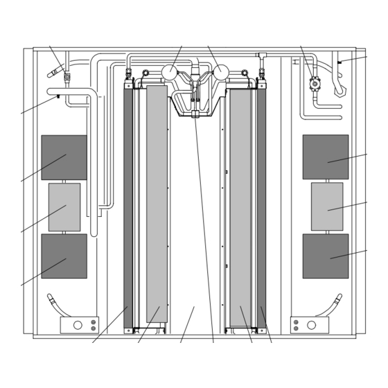
- Page 8 1. Receiver 7. Ambient Air Switch 2. Fusible Plug 8. Filter-Drier Outlet Valve 3. Condenser Coil 9. Filter-Drier 4. Condenser Fan and Motor 10. Receiver Outlet or Filter- 5. Discharge Line Valve Drier Inlet Valve 6. Discharge Check Valve 11. Sight Glass Figure 1-2.
-
Page 9: Electrical Control Panel Components For Models With Rotron Brushless Motors
20 21 22 1. Booster Pump Relay (BPR) 20. Run Control Switch #1 (RCS1) 2. A/C Relay (ACR) 21. Circuit Breaker (CB3) --- 40 Amp 3. Heat Relay (HR) 22. Circuit Breaker (CB2) --- 40 Amp 4. Heat Relay #2 (HR2) 23. -
Page 10: Refrigeration System Component Specifications
REFRIGERATION SYSTEM COMPONENT e. High Pressure Switch (HPS) SPECIFICATIONS R-134a: a. Refrigeration Charge Opens at: 425 10 psig (30 0.7 kg/cm@) R-134a: 16 lb. (7.3 kg) Closes at: 300 10 psig b. Compressor (21 0.7 kg/cm@) Model: No. of Cylinder: f. -
Page 11: Electrical Specifications
1.3 ELECTRICAL SPECIFICATIONS 1.4 SAFETY DEVICES a. Evaporator Blower Motor Safety devices protect system components from damage caused by unsafe operating conditions. Evaporator Motor Brushless Factory Lubri- If the High Pressure Switch (HPS) or Low Pressure cated (addi- Switch (LPS) opens due to unsafe operating conditions, Bearing Lubrication tional grease the A/C operation will automatically stop. -
Page 12: System Operating Controls And Components
SYSTEM OPERATING CONTROLS AND c. Thermal Switches COMPONENTS Low Ambient Thermostat (LATH) a. Temperature Controller (Thermostat) The Low Ambient Thermostat (LATH) monitors the vehicles outside temperature. The switch opens a set of The Temperature Controller is a thermostat that contacts at 45 5_F (7.2 0.35 _C) and closes at 55 senses and controls the vehicle interior air temperature. - Page 13 Clutch Relay (CR) Evaporator Fan Relay #1 (EFR1) Evaporator Fan Relay #1 (EFR1) is located in the The Clutch Relay (CR) is located in the electrical electrical control panel. When the Air Conditioning control panel. When the CR relay is energized, a set of Switch (ACS) is placed in either the COOL or HEAT internal contacts will close to engage the compressor position, EFR1 relay is energized.
-
Page 14: Reheat Coolant Valve
1.6 REHEAT COOLANT VALVE 1.7 LIQUID LINE SOLENOID VALVE The Liquid Line Solenoid Valve (LLS) is located in The Reheat Coolant Valve (RCV) is located in the the evaporator section of the unit on the roof of the bus evaporator section of the unit on the roof of the bus. (See (See Figure 1-1.) The electrically operated solenoid valve Figure 1-1.) The valve is an electrically operated solenoid is energized when the Clutch Relay (CR) is energized. -
Page 15: Refrigeration Flow Cycle
1.10 REFRIGERATION FLOW CYCLE OPTIONAL 1. Evaporator Coils 9. Condenser Coils 16. Unloader Pressure Port 2 2. Inline Sight Glass 10. Discharge Service Valve 17. Unloader Pressure Port 3 3. Low Pressure Service Port 11. Suction Service Valve 18. Condenser Fan Pressure Port 4. -
Page 16: Operation
SECTION 2 OPERATION 2.1 STARTING AND STOPPING INSTRUCTIONS position. In this position, the thermostat cycles the compressor on and off to control vehicle interior a. Starting temperature. 1. Start the vehicle engine. When the driver’s A/C Switch (ACS) is placed in the 2. -
Page 17: Cooling (Air Conditioning) Cycle Operation - Reheat Control
Speed Relay (CSR) opens a set of normally closed the valve allowing flow of engine coolant to the heater contacts to switch to low speed condenser fan operation. coil for heating. At this point, the thermostat also applies power to plug On a rising temperature to +1˚F above the J1, pin no.6 and pin no. -
Page 18: Heat Operation
2.3.3 Heat Operation (See Figure 2-3.) RISING The driver’s A/C Switch (ACS) is placed in the HEAT TEMPERATURE position to activate the heating cycle. With this switch in the HEAT position, 24-vdc is applied to energize Heat 5˚F ABOVE Relay (HR) and Evaporator Speed Relays (ESR1 and SETPOINT ESR2). -
Page 19: Cooling Cycle - High Speed Vent Mode Operation
Energized Circuit De-energized Circuit Figure 2-4. Cooling Cycle--- High Speed Vent Mode Operation... -
Page 20: High Speed Unloaded (2-Cylinder Operation) Cool Mode Operation
Energized Circuit De-energized Circuit Figure 2-5. High Speed Unloaded (2-cylinder operation) Cool Mode Operation... -
Page 21: High Speed Semi-Loaded (4-Cylinder Operation) Cool Mode Operation
Energized Circuit De-energized Circuit Figure 2-6. High Speed Semi-Loaded (4-cylinder operation) Cool Mode Operation... -
Page 22: High Speed Fully Loaded (6-Cylinder Operation) Cool Mode Operation
Energized Circuit De-energized Circuit Figure 2-7. High Speed Fully Loaded (6-cylinder operation) Cool Mode Operation... -
Page 23: High Speed Unloaded (2-Cylinder Operation) Cool With Reheat Mode Operation
Energized Circuit De-energized Circuit Figure 2-8. High Speed Unloaded (2-cylinder operation) Cool with Reheat Mode Operation... -
Page 24: Heating Cycle - Low Speed Heat Mode Operation
Energized Circuit De-energized Circuit Figure 2-9. Heating Cycle --- Low Speed Heat Mode Operation 2---9/2---10... -
Page 25: Troubleshooting
SECTION 3 TROUBLESHOOTING INDICATION/ REFERENCE TROUBLE POSSIBLE CAUSES SECTION 3.1 UNIT WILL NOT COOL Compressor will not run V-Belt broke or defective Check Compressor malfunction See Note Clutch malfunction Check/Replace Safety device open Electrical malfunction A/C switch defective Check A/C relay defective Check/2.3 Low Ambient Thermostat open 1.5.c... -
Page 26: Abnormal Noise And Vibrations
INDICATION/ REFERENCE TROUBLE POSSIBLE CAUSES SECTION 3.3 ABNORMAL PRESSURE CONT’D Low suction pressure Suction service valve partially closed Open Filter-drier inlet and outlet valves partially closed Check/Open Filter-drier partially plugged 4.10 Low refrigerant charge Expansion valve malfunction Restricted air flow Liquid line solenoid malfunction 4.16 Low evaporator air flow... -
Page 27: No Heating Or Insufficient Heating
3.6 NO EVAPORATOR AIR FLOW OR RESTRICTED AIR FLOW No evaporator air flow Motor burnout 4.18 Fan damage 4.18 Return air filter dirty Check/4.19 Fan Relay EFR1 defective Check/1.5/Replace Safety device open Wiring polarity incorrect Check/5.1 3.7 EXPANSION VALVE MALFUNCTION Low suction pressure with Low refrigerant charge high superheat... -
Page 28: Service
SECTION 4 SERVICE WARNING BEWARE OF ROTATING FAN BLADES AND UNANNOUNCED STARTING OF FANS. 4.1 MAINTENANCE SCHEDULE UNIT REFERENCE REFERENCE OPERATION OPERATION SECTION a. Daily Maintenance Pre-trip inspection --- after starting Check tension and condition of Compressor V-belt(s) None b. Weekly Inspection and Maintenance Perform daily inspection 4.1.a Check condenser, evaporator coils and air filters... -
Page 29: System Pumpdown
hoses are common with the center hose as well as each refrigerant into condenser coil and receiver tank as other. When the low and high side valves are frontseated follows: (closed), the high and low side hoses are isolated from a. -
Page 30: Refrigerant Leak Check
It is volume displacement, at atmospheric pressure) A pump possible to remove more refrigerant by cooling of this capacity is available through the Carrier Service the refrigerant cylinder in a container of ice. Parts, CTD P/N 07-00176-01. -
Page 31: Evacuation Manifold
5. Evacuation Manifold --- A evacuation manifold is alternate sources of heat may be used to raise system recommended for connecting the equipment needed for temperature if necessary. a proper evacuation. The evacuation manifold can be 1. Before refrigerant removal and evacuation, leak made easily as shown in Figure 4-3. -
Page 32: Adding Refrigerant To System
1. Condenser Coils 10. Suction Service Valve 2. Filter-Drier Outlet Service Valve 11. Compressor 3. Filter-Drier 12. Reclaimer 4. Filter-Drier Inlet Service Valve 13. Vacuum Manifold 5. Receiver 14. Thermistor Vacuum Gauge 6. Thermostatic Expansion Valves 15. Compound Gauge 7. High Pressure Service Port 16. -
Page 33: Checking Pressure Switches
4.10 FILTER-DRIER REMOVAL 4.11 CHECKING PRESSURE SWITCHES If the sight glass on the receiver appears to be flashing The recommended procedure for testing the High or excessive bubbles are constantly moving through the Pressure Switch (HPS), Low Pressure Switch (LPS), sight glass, the unit may have a low refrigerant charge, or Condenser Fan Speed Switch (CFS), and Unloader the filter-drier could be partially plugged. -
Page 34: Thermostatic Expansion Valve
WARNING 7. Attach the sensor bulb just below center of the suction line (4 or 7 o’clock position viewing from cross Do not use a nitrogen cylinder without a section to the suction line, see Figure 4-8). This area must pressure regulator. -
Page 35: Removing The Heater Coil
7. Note the temperature of the suction gas at the c. Drain coil by removing enough coolant from sensor bulb. vehicle cooling system. d. Disconnect water line from the coil. 8. Subtract the saturation temperature determined in Step 6 from the average temperature measured in Step CAUTION 7. -
Page 36: Servicing The Reheat Coolant Valve
4.15 SERVICING THE REHEAT COOLANT VALVE 2. Open the vent fitting at the top of the outlet header of the heater coil. The coolant valve requires no maintenance unless a malfunction to the internal parts or coil occurs. This may 3. -
Page 37: Servicing The Liquid Line Solenoid Valve
4.16 SERVICING THE LIQUID LINE SOLENOID 3. Disassemble valve and replace defective parts. VALVE 4. Assemble valve and leak check under valve while under pressure. The Liquid line solenoid valve is very similar to the c. To replace the entire valve: coolant valve. -
Page 38: Servicing The Evaporator Fan Blower Motor Assembly
4.18 SERVICING THE EVAPORATOR FAN This could cause insufficient cooling or heat and possible BLOWER MOTOR ASSEMBLY frost build up on the coil. a. Removing and Disassembling Remove filters as follows: 1. Place run control switch to the OFF position. a. -
Page 39: Checking The Compressor Oil Level
A liters) refrigeration oil container. Using the Robinair small Teflon seat ring at bottom of piston must be compressor oil pump (Carrier Transicold P/N 14388) is removed. recommended. 2. Remove the high pressure switch and install on... -
Page 40: Adding Oil To Service Replacement Compressor
6. Backseat valve to remove hose from suction a. To Remove Oil From the Compressor service valve and replace service valve caps. 1. If the oil level recorded in paragraph 4.20.2 is above 1/2 of the sight glass, remove oil from the Gauge Suction compressor. - Page 41 Table 4-2. R-134a Temperature--- Pressure Chart BOLD NO. = Inches Mercury Vacuum (cm Hg Vac) Temperature Pressure Temperature Pressure Psig Kg/cm@ Psig Kg/cm@ ---40 ---40 14.6 37.08 0.49 ---1 26.1 1.84 1.80 12.3 31.25 0.42 ---35 ---37 27.8 1.95 1.92 ---30 ---34 24.64 0.33...
-
Page 42: Electrical 5.1 Introduction
SECTION 5 ELECTRICAL 5.1 INTRODUCTION This section includes electrical wiring schematics for model 68RF50 for NEOPLAN-LA. The schematic shown in this section is for R-134a refrigerant systems. -
Page 43: Electrical Wiring Schematic Diagram (68Rf50 With Rotron Brushless Motors)
Figure 5-1. Electrical Wiring Schematic Diagram (68RF50 with Rotron Brushless Motors), Dwg. No. C-070-935, Rev C (Sheet 1 of 2) - Page 44 Figure 5-1. Electrical Wiring Schematic Diagram (68RF50 with Rotron Brushless Motors), Dwg. No. C-070-935, Rev C (Sheet 2 of 2) 5---3/5---4...
Need help?
Do you have a question about the Transicold 68RF50 Neoplan-LA and is the answer not in the manual?
Questions and answers