
Related Manuals for Carrier 68RM35-610


Summary of Contents for Carrier 68RM35-610
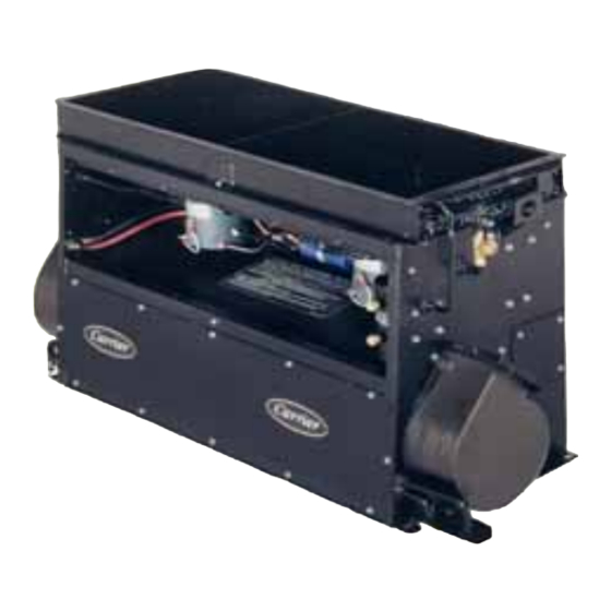
- Page 1 Transport Air Conditioning OPERATION AND SERVICE 68RM35- -610 MICROMAX / MCHX Rear Mount Air Conditioning Unit T--356 03/11...
- Page 2 OPERATION AND SERVICE MANUAL AIR CONDITIONING EQUIPMENT Rearmount 68RM35- -610 Micromax / MCHX...
- Page 3 SAFETY SUMMARY GENERAL SAFETY NOTICES The following general safety notices supplement the specific warnings and cautions appearing elsewhere in this manual. They are recommended precautions that must be understood and applied during operation and maintenance of the equipment covered herein. The general safety notices are presented in the following three sections labeled: First Aid, Operating Precautions and Maintenance Precautions.
- Page 4 SPECIFIC WARNING AND CAUTION STATEMENTS The statements listed below are applicable to the refrigeration unit and appear elsewhere in this manual. These recommended precautions must be understood and applied during operation and maintenance of the equipment covered herein. SPECIFIC WARNINGS AND CAUTIONS WARNING Be sure to observe warnings listed in the safety summary in the front of this manual before performing maintenance on the hvac system.
-
Page 5: Table Of Contents
TABLE OF CONTENTS PARAGRAPH NUMBER Page SAFETY SUMMARY ..............Safety- -1 GENERAL SAFETY NOTICES . - Page 6 TABLE OF CONTENTS - - Continued PARAGRAPH NUMBER Page 2.3.6 Compressor Unloader Control ............2--3 2.3.7 Evaporator Fan Speed Selection .
- Page 7 TABLE OF CONTENTS - - Continued PARAGRAPH NUMBER Page EVACUATION AND DEHYDRATION ........... . 4--5 4.6.1 General .
-
Page 8: List Of Illustrations
LIST OF ILLUSTRATIONS FIGURE NUMBER Page Figure 1-1. A/C Component Identification ............1--1 Figure 1-2. -
Page 9: List Of Tables
LIST OF TABLES TABLE NUMBER Page Table 1-1. Model Number Chart ..............1--2 Table 1-2. -
Page 10: Description
SECTION 1 DESCRIPTION 1.1 INTRODUCTION mounted compressor. To complete the system, the air conditioning and heating equipment interfaces with This manual contains Operating Instructions, Service electrical cabling, refrigerant piping, engine coolant Instructions and Electrical Data for Model 68RM35 Air piping (for heating), duct work and other components Conditioning and Heating equipment listed in Table 1-1. -
Page 11: Table 1-1. Model Number Chart
Table 1-1. Model Number Chart MODEL BATTERY COOLER CONTROL CONDENSER EVAPORATOR FILTER NUMBER MOTOR MOTOR 68RM35--610--1 Reheat Wound Field Wound Field Cleanable 68RM35--610--2 Reheat Wound Field Wound Field Cleanable Permanent Magnet 68RM35--610--3 Reheat Permanent Magnet Cleanable w/Resistor Permanent Magnet 68RM35--610--4 Reheat Permanent Magnet Cleanable... -
Page 12: Evaporator System
ROADSIDE CURBSIDE (RS) (CS) Model/Serial Number Plate Condenser Fan Motor (CM1) Discharge Pressure Transducer Filter--Drier Outlet Valve Evaporator Fan Housing, Curbside Filter--Drier Discharge Line Connection Ambient Temperature Sensor Suction Line Connection Filter--Drier Inlet Valve Suction Pressure Transducer Condenser Fan Motor (CM2) Evaporator Fan Motor (EFM2) Receiver Liquid--Suction Heat Exchanger(if fitted) -
Page 13: Fresh Air Connection
A controller programmed for clutch cycle will nents de--energize the compressor clutch and allow the The system is operated by a Carrier Transicold system to operate in the vent mode until further cooling Micromax microprocessor controller (Figure 1-4) which is required. A controller programmed for reheat will... - Page 14 Wound Field- -Typical 15 16 Permanent Magnet- -Typical 16 17 18 Brushless- -Typical Relay Board Power Terminal Block Logic Board Condenser Speed Relay CB5 -- Condenser Motor #1 Condenser Fan #1 Relay CB4 -- Condenser Motor #2 Condenser Fan #2 Relay CB3 -- Evaporator Motor #1 Evaporator Fan #1 Relay CB2 -- Evaporator Motor #2...
-
Page 15: Relay Board (12--00371--01)
1.3 RELAY BOARD (12- -00371- -01) a. Relays c. LEDS Energizes evaporator fans in low speed D 2 Relay K2 output active (evaporator fan high Energizes evaporator fans in high speed speed relay energized) (not energized in low speed). D 6 Relay K1 output active (evaporator fan K 7 Energizes condenser fans in low speed relay K 8 Energizes condenser in high speed... -
Page 16: Logic Board
1.4 LOGIC BOARD J1 Logic board power in. J7 Diagnostics interface (RS232, DB9). J2 Micromate Display interface. D2 Blinks once per second in normal operation. J3 Manual control inputs. On steady to indicate alarms detected. J4 Interlock Inputs D3 Off In normal operation, blinks out alarm (WTS, low pressure switch etc.) codes (2 digits each) when alarms detected. -
Page 17: Control Panel (Full Function Controller)
1.6 CONTROL PANEL (Full Function Controller) Display FAN SPEED Button DOWN Button -- decrease selection FRESH AIR Button (Not Applicable This UP Button -- increase selection System) VENT (Only) Button TEMPERATURE ( Inside / Outside) AUTO Button (Automatic Control) Button COOLING (Only) Button ON/OFF Button HEAT (Only) Button... -
Page 18: Electrical Specifications Condenser Motors
System components are protected from damage b. Fuses and Circuit Breakers caused by unsafe operating conditions with safety devices. Carrier Transicold supplied safety devices The Relay Board is protected against high current by an include a high pressure switch (HPS), low pressure OEM supplied 150 amp fuse or circuit breaker. -
Page 19: Air Conditioning Refrigeration Cycle
The refrigerant leaves the receiver and passes through water pump. A solenoid operated reheat coolant valve the liquid/suction heat exchanger. The liquid/suction may be supplied by the bus manufacturer or by Carrier heat exchanger further cools the liquid by transferring Transicold, depending on the application. The controller heat to the suction gas. - Page 20 20 19 LEGEND Moisture Indicator Expansion Valve Receiver Expansion Valve Equalizer Line DISCHARGE Service Port, High Side Liquid Line Solenoid Valve Pressure Transducer, High Side LIQUID Expansion Valve Bulb High Pressure Switch Filter--Drier Inlet Service Valve SUCTION Low Pressure Switch Filter--Drier Outlet Service Valve Auxiliary Cooler Suction Connection COOLANT...
-
Page 21: Operation
SECTION 2 OPERATION 2.1 STARTING, STOPPING AND OPERATING 5. The Micromate Control Panel (see Figure 1-8) may INSTRUCTIONS be programmed to display the set point temperature or return air temperature. To determine which dis- 2.1.1 Power to Logic Board play temperature is programmed, press the TEM- PERATURE button so that the OUTSIDE AIR indica- Before starting, electrical power must be available from tor is illuminated. -
Page 22: Stopping
Placing the ON/OFF switch in the OFF position or pressing the Micromate ON/OFF button will stop the The system is operated by a Carrier Transicold system operation by removing power to the Logic Micromax microprocessor controller which consists of a Board. -
Page 23: Temperature Control
2.3.1 Temperature Control temperature control, suction pressure control and discharge pressure control are as follows. Temperature is controlled by maintaining the return air temperature measured at the return air grille. a. Temperature Control 2.3.2 Cooling The unloaders are used to control system capacity by controlling compressor capacity. - Page 24 2.3.8.1 Fan Motor Operation Sequence, Permanent speed relay (ESR) to the orange motor control leads Magnet and Wound Field Motors signaling low speed operation. When condenser fan operation is required, the When high speed evaporator fan operation is required, microprocessor energizes (grounds thru JP2--5) the the microprocessor energizes the coil of the K2 relay by condenser fan ON relay (K7).
-
Page 25: Table 2-1. Controller Test List
UP arrow to HVAC technician who has been trained on scroll from the last to the first parameter. When scrolling Carrier Model RM system design. The through the parameters, the current parameter will be control configuration is preset by the displayed for two seconds. -
Page 26: Table 2-2. Parameter Codes
Table 2-2. Parameter Codes CODE CODE NAME DESCRIPTION Return Air This value is the temperature measured by the return air sensor. If the sensor Temperature is shorted it will display CL. If it is open circuited it will display OP. Coil Temperature Not used. - Page 27 Table 2-2. Parameter Codes - - Continued Code Code Name Description Compressor Hours This is the number of hours of operation that the compressor has run with the High clutch energized in thousands. Compressor Hours This is the number of hours of operation that the compressor has run with the clutch energized in hundreds, tens and ones.
-
Page 28: Table 3-1 Error Codes
SECTION 3 TROUBLESHOOTING CAUTION Do not under any circumstances attempt to service the microprocessor. Should a problem develop with the microprocessor, replace it. 3.1 SELF DIAGNOSTICS that the Logic Board STATUS and CODE LED’s (see Figure 1-6) flash simultaneously. The Micromate A self test is performed by the Micromax Logic Board control panel display will indicate errors with the code each time the board is powered up. - Page 29 3.3.1 Troubleshooting CAN Communication 14. Send the following command to set Fan Speed to Low. NOTE On the 12--00693--00 board the CAN commu- T18EF19218FDFFFFFFFFFFFFFF nication line pins are on J4--PIN 14(CAN High, Then ’enter key’ and wait at least 1 minute for re- CAN_H) and J4--PIN 15 (CAN Low, CAN_L).
-
Page 30: Table 3-2 Alarm Codes
Table 3-2 Alarm Codes ALARM TITLE CAUSE REMEDY CONTROLLER RESPONSE Coil Freeze Coil temperature is Check causes of coil An alarm will be gener- less than 32°F and freezing. (Refer to ated and the system will the compressor is op- section 3.3.8) shutdown. - Page 31 Table 3-2. Alarm Codes - - Continued ALARM TITLE CAUSE REMEDY CONTROLLER RESPONSE High Discharge Pressure High discharge pres- Check discharge The clutch is de--ener- sure switch open or pressure transducer gized for the minimum wiring defective. reading, wiring or off time.
-
Page 32: Table 3-3. General System Troubleshooting Procedures
Table 3-3. General System Troubleshooting Procedures INDICATION/ REFERENCE POSSIBLE CAUSES TROUBLE SECTION 3.3.3 System Will Not Cool Compressor will not run Active system alarm V--Belt loose or defective Check Clutch coil defective Check/Replace Clutch malfunction Check/Replace Compressor malfunction See Table 1-2 Electrical malfunction Coach power source defective Check/Repair... - Page 33 Table 3-3 General System Troubleshooting Procedures - - Continued INDICATION/ REFERENCE POSSIBLE CAUSES TROUBLE SECTION 3.3.6 Abnormal Noise Or Vibrations - - Continued Condenser or evaporator fans Loose mounting hardware Check/Tighten Defective bearings Replace Blade interference Check Blade missing or broken Check/Replace 3.3.7 Control System Malfunction Will not control...
- Page 34 SECTION 4 SERVICE WARNING Be sure to observe warnings listed in the safety summary in the front of this manual before perform- ing maintenance on the hvac system WARNING Read the entire procedure before beginning work. Park the coach on a level surface, with parking brake applied.
- Page 35 A R--134a manifold gauge/hose set with self--sealing hoses is required for service of models covered within this manual. The manifold gauge/hose set is available from Carrier Transicold. (Carrier Transicold P/N 07--00294--00, which includes items 1 through 6, Figure 4-2.) To perform service using the manifold...
- Page 36 4.4 PUMPING THE SYSTEM DOWN OR REMOV- d. Frontseat the compressor suction service valve to ING THE REFRIGERANT CHARGE trap refrigerant in the high side of the system between the compressor suction service valve and the filter-- drier inlet valve. Wait 5 minutes to verify that system NOTE remains in a vacuum.
- Page 37 1. Filter--Drier 5. Thermistor Vacuum 2. Filter--Drier Inlet Gauge Service Valve 6. Vacuum Pump 3 Manifold Gauge 7. Reclaimer 1. Discharge Service 4. Vacuum Pump 8. Refrigerant Cylinder Valve and Port 5. Reclaimer 4. Suction Service 2. Suction Service 6. Refrigerant Cylinder Valve and Port Valve and Port 7.
- Page 38 e. Remove test gas and replace filter--drier. i. Start vacuum pump and open all valves. Dehydrate unit to 500 microns Hg vacuum. f. Evacuate and dehydrate the system. (Refer to para- graph 4.6.) j. Close off pump valve, and stop pump. Wait five min- utes to see if vacuum holds.
- Page 39 g. Prepare the cylinder as required to allow vapor charg- 4.9 CHECKING AND REPLACING HIGH OR LOW ing. Backseat the manifold suction valve and charge PRESSURE SWITCH vapor to build 30 psig pressure on the manifold suc- tion gauge. Close cylinder valve and frontseat suction WARNING manifold set.
- Page 40 4.10 FILTER- -DRIER 4.11 SERVICING THE LIQUID LINE SOLENOID VALVE 4.10.1 To Check Filter- -Drier The Liquid line solenoid valve (Figure 4-8) is very similar The filter--drier (see Figure 4-7) must be changed if the to the reheat coolant valve. It requires no maintenance drier is partially restricted or service has been performed unless a malfunction to the internal parts or coil occurs.
- Page 41 4.11.3.Replace Entire Valve a. Perform a low side pump down, refer to paragraph 4.4.1. Remove coil and plunger assembly and un-- braze valve from lines. b. Remove valve assembly from bracket. c. Disassemble new valve, to protect internal parts, and solder to lines.
- Page 42 4.12.2 Superheat Measurement 4.13 REPLACING RETURN AIR FILTERS The return air filters are located behind the return air NOTE grill, inside the vehicle. All readings must be taken from the TXV bulb The filters should be checked for cleanliness location and out of the direct air stream. periodically depending on operating conditions.
- Page 43 Check oil level in service replacement (55 to 80 ft--lbs suction and 20 to 30 ft--lbs discharge service valves). compressor. (Refer to paragraphs 1.7 and 4.14.4.) k. Leak check connections and replace filter--drier. Re- fer to paragraph 4.5. l. Using refrigerant hoses designed for vacuum service, connect a vacuum pump (see Figure 4-4) and evacu- ate compressor to 500 microns.
- Page 44 g. Noting the position of the wire, remove the three bolts e. To remove oil and bring the level to the 1/2 sightglass holding the coil to the compressor. maximum, do the following: 1. With the system off, connect a manifold gauge set to h.
-
Page 45: Table 4-1. Temperature Sensor Resistance
h. Disconnection of the suction pressure transducer will the pressure transducer locations. If the problem cause an “A15” alarm. Once the transducer is recon- moves with the transducer replace the faulty trans- nected, the alarm will go to inactive and can then be ducer. -
Page 46: Table 4-2. Pressure Transducer Voltage
Table 4-2. Pressure Transducer Voltage “/hg Voltage Psig Voltage Psig Voltage Psig Voltage Psig Voltage Psig Voltage 20” 0.369 0.858 1.397 1.936 2.475 3.014 10” 0.417 0.907 1.446 1.985 2.524 3.063 Psig Voltage 0.956 1.495 2.034 2.573 3.112 0.466 1.007 1.544 2.083 2.622... - Page 47 4.19.2 Routine Examination and Cleaning a. At regular maintenance periods, remove brush covers and clean and examine motor interior. b. Remove all foreign material, such as dirt and carbon dust . Clean by vacuum if possible to avoid blowing foreign matter into the motor. c.
- Page 48 4.20 SERVICING THE REHEAT COOLANT VALVE b. Failure to open may be caused by: 1. Coil burned out or an open circuit to coil reheat coolant valve (RCV) requires no connections. maintenance unless a malfunction of the internal parts or coil damage occurs. This may be caused by foreign 2.
-
Page 49: Table 4-3. Logic Board Configuration
Control configuration is preset at the factory and resetting of the parameters is not advised. If a replacement Logic Board is installed, it is necessary to match the configuration jumpers (see Figure 1-6) to the original board. Table 4-3 provides a list of jumper functions. Carrier is not responsible for failures or damage resulting from unauthorized changes. -
Page 50: Table 4-4. R--134A Temperature -- Pressure Chart
Table 4-4. R- -134a Temperature - - Pressure Chart Temperature Vacuum Temperature Pressure ° ° ° ° “/hg Kg/cm@ Psig Kg/cm@ --40 --40 14.6 37.08 0.49 24.5 1.72 1.69 26.1 1.84 1.80 12.3 31.25 0.42 27.8 1.95 1.92 --30 --34 24.64 0.33 29.6... - Page 51 Logic Board connector J2. When the micromate is used for service or diagnostic purposes, it is wired in the same manner as shown for drivers panel use, thru the optional Service Port. Contact your Carrier Transicold service representative or call the technical hot line at 800--450--2211 for questions related to the schematic for your specific model.
- Page 52 98--03319 A Figure 5- -1. Wiring Schematic - - Legend - - 68RM35- -610 (All) T--356 03/11 5--2...
- Page 53 98--03319 A Figure 5- -2. Wiring Schematic - - Control Circuit - - 68RM35- -610 (All) 03/11 T--356 5--3...
- Page 54 ‘ POWER CIRCUIT - - PERMANENT MAGNET MOTORS 98--03319 A Figure 5- -3. Wiring Schematic - - Power Circuit - - 68RM35- -610- -3, - -4, - -5 T--356 03/11 5--4...
- Page 55 ‘ POWER CIRCUIT - - WOUND FIELD MOTORS 98--03319 A Figure 5- -4. Wiring Schematic - - Power Circuit - - 68RM35- -610- -1, - -2 03/11 T--356 5--5...
- Page 56 ‘ POWER CIRCUIT - - BRUSHLESS MOTORS 98--03319 A Figure 5- -5. Wiring Schematic - - Power Circuit - - 68RM35- -610, 6, - -7, - -8, - -9 T--356 03/11 5--6...
- Page 57 INDEX Fan Motor Operation Sequence, 2--3 Air Filter, 4--9 Fan Motor Operation Sequence, Brushless Mo- Alarm, 2--4, 3--1 tors, 2--4 Alarm Clear, 3--1 Fan Motor Operation Sequence, Permanent Mag- net and Wound Field Motors, 2--4 Alarm Codes, 3--1 Filter--Drier, 1--11, 4--7 Alarm Queue, 3--1 Filter--Drier Inlet Valve, 1--11 Ambient Lockout, 1--9...
- Page 58 INDEX Pre--Trip Inspection, 2--2 Temperature Control, 2--3 Pressure Transducer, 1--9, 4--12 Temperature Pressure Chart, 4--17 Pump Down, 4--3, 4--4 Temperature Sensor, 1--9, 4--12, 4--13, 4--14, 4--15 Thermostatic Expansion Valve, 1--8, 1--11, 4--8 Troubleshooting, 3--1 Refrigerant Charge, 1--8, 4--3, 4--4, 4--5, 4--6 Troubleshooting No CAN Communication, 3--2 Refrigerant Removal, 4--3, 4--4 Refrigeration Cycle, 1--10...
- Page 59 Carrier Corporation Fax: 1- -717- -764- -0401 Transport Air Conditioning Group P.O. Box 4805 Syracuse, N.Y. 13221 U.S A www.carrier.transicold.com A member of the United Technologies Corporation family. Stock symbol UTX ©2011 Carrier Corporation D Printed in U. S. A. 0311...
Need help?
Do you have a question about the 68RM35-610 and is the answer not in the manual?
Questions and answers