Table of Contents
Advertisement
Quick Links
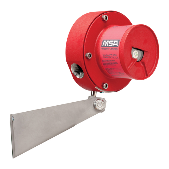
FlameGard® 5
UV/IR-E
Ultraviolet/Infrared
Flame Detector
The information and technical data disclosed in
this document may be used and disseminated
only for the purposes and to the extent
specifically authorized in writing by General
Monitors.
Instruction Manual
09/09
General Monitors reserves the right to change
published specifications and designs without
prior notice.
Part No.
MAN5UVIRE-EU
Revision
0
Advertisement
Table of Contents

Related Manuals for MSA FlameGard 5 UV/IR-E


Summary of Contents for MSA FlameGard 5 UV/IR-E
- Page 1 FlameGard® 5 UV/IR-E Ultraviolet/Infrared Flame Detector The information and technical data disclosed in this document may be used and disseminated only for the purposes and to the extent specifically authorized in writing by General Monitors. Instruction Manual 09/09 General Monitors reserves the right to change published specifications and designs without prior notice.
- Page 2 FlameGard 5 UV/IR-E Warranty Statement MSA warrants the FlameGard 5 UV/IR-E to be free from defects in workmanship or material under normal use and service within two years from the date of shipment. MSA will repair or replace without charge any such equipment found to be defective during the warranty period.
- Page 3 MSA AUER GmbH Thiemannstraße 1 D-12059 Berlin declares that the product MSA AUER FlameGard 5 UV/IR-E based on the EC-Type Examination Certificates : SIRA 10 ATEX 1365 complies with the ATEX directive 94/9/EC, Annex III. Quality Assurance Notification complying with Annex IV of the ATEX Directive 94/9/EC has been issued by SIRA Certification Service , Notified Body number: 0518.
-
Page 4: Table Of Contents
FlameGard 5 UV/IR-E Table of Contents Page Introduction ...................... 2 General Description ................2 Principle of Operation ................ 3 Specifications ...................... 6 System Specifications................ 6 Mechanical Specifications..............7 Electrical Specifications ..............7 Environmental Specifications............. 8 Modbus RTU Protocol................ 8 Installation ...................... -
Page 5: Introduction
These reactions emit radiation covering the Infrared, Ultraviolet and the Visible Spectral Regions. The MSA FlameGard 5 UV/IR-E is an Ultraviolet/Infrared (UV/IR) Flame Detector. It detects the Ultraviolet and Infrared spectral regions of the flame to produce a system which is highly immune to false alarms caused by lightning, arc-welding, hot objects, and other sources of radiation. -
Page 6: Principle Of Operation
FlameGard 5 UV/IR-E Principle of Operation UV Detector The Flame Detector contains an ultraviolet phototube that responds to Ultra-Violet (UV) radiation in the 185 to 260 nanometer region (Figure 2). When radiation from a flame reaches the cathode plate within the UV detector tube, electrons are ejected from the cathode plate. - Page 7 Figure 2 Spectral Response of UV and IR Detectors UV/IR Flame Detector The FlameGard 5 UV/IR-E is a discriminating UV/IR Detector, which makes use of an ultraviolet radiation sensitive phototube in addition to an infrared detector (see figure 2). This combination provides a flame detection system, which is highly immune to false alarms.
- Page 8 FAULT, it may take up to two minutes for the unit to detect an obstruction. Alarm Test The FlameGard 5 UV/IR-E have a built-in Alarm Test feature. This test may be activated via the serial communications port (see Section 3-6 Terminal Connections).
-
Page 9: Specifications
1. Response Times and Field of View data have been derived by testing the FlameGard 5 UV/IR-E with a 1 square foot gasoline fire. One cup of unleaded gasoline on top of a one inch layer of water was ignited for each test. These are typical values and different results may occur depending on the variation of each fire. -
Page 10: Mechanical Specifications
FlameGard 5 UV/IR-E Mechanical Specifications Enclosure material Material: Stainless Steel 316 Colour: Natural Dimensions: Diameter 3.3 in (8.4 cm) Length 5.4 in (13.7 cm) Weight 5lbs (2.3 kg) Cable Entries: 2 x M20 Electrical Specifications Supply voltage range: 20 to 36 VDC... -
Page 11: Environmental Specifications
FlameGard 5 UV/IR-E Environmental Specifications Operating temperature range: -40°C to 90°C -40°F to 194°F Storage temperature range: -40°C to 90°C -40°F to 194°F Humidity range: 0 to 100% RH non-condensing Modbus RTU Protocol For detailed information on data format, read commands, write commands, register details,... -
Page 12: Installation
Detector Field of View Each FlameGard 5 UV/IR-E Flame Detector has a maximum cone of vision of 120º. This Cone has its vertex at the center of the detector (see figure 3A-1, 3A-2, and 3A-3). -
Page 13: Detector Installation
Detector Installation The FlameGard 5 UV/IR-E Detector should be mounted tilting downwards so that dust/moisture will not accumulate on the window. (The detector should be mounted in locations which will avoid either people or objects from obscuring the detector’s Cone of Vision.) -
Page 14: Interconnecting Cable Guidelines
Complete all cable insulation tests before connecting the cable at either end. • MSA do not recommend the use of cable shoes or crimps on any junction box or housing wiring terminals. Poor crimping can cause bad connection when unit experiences temperature variations. - Page 15 FlameGard 5 UV/IR-E Figure 3A-1 Horizontal Field of View Figure 3A-2 Vertical Field of View...
- Page 16 FlameGard 5 UV/IR-E Figure 3-B Outline Drawing...
-
Page 17: Terminal Connections
Figure 3-D Strip Length Four of the six positions on the terminal block have functions which depend on the FlameGard 5 UV/IR-E version selected. The remaining two positions are reserved for the power connections. Figure 3-C outlines the terminal block connections by version. - Page 18 FlameGard 5 UV/IR-E POWER INPUTS +B and 0V These are the power connections. The supply voltage range is 20 to 36 VDC at the detector (low voltage is detected at 18.5 VDC). The following maximum cable lengths apply for a +24VDC supply (maximum 20 ohm loop):...
- Page 19 FlameGard 5 UV/IR-E RELAY OUTPUT (Figure 3-E) A1 ALM Description: This connection is the WARN relay contact. The WARN output is immediate and can be normally energised or normally de-energised, latching or non-latching. WARN relay contact rating is 1A @ 30VRMS/42.2VPK Resistive.
-
Page 20: User Selectable Options
FlameGard 5 UV/IR-E FIELD LOOP OUTPUTS (Figure 3 – F) LP+ and LP- Description: These are the field loop connections to a fire card such as MSA’ IN042. The FAULT relay, when energised, inserts a 5600ohms, 2Watt End-Of-Line resistor across these connections. - Page 21 FlameGard 5 UV/IR-E SENSITIVITY and ALARM-TIME-DELAY Options Sensitivity (%) Alarm-time-delay (sec) WARN and ALARM Relay Options WARN (1) Relay ALARM (2) Relay LA = Latching NL = Non Latching EN = Energised DE = De-Energised The above options have been represented pictorially on the label attached to the Program...
-
Page 22: Factory Default Settings
Factory Default Settings Return to Factory Default settings only affects FlameGard 5 UV/IR-E versions with serial communications capabilities. It provides a mechanism to restore the communications parameters, should they be unknown or corrupted. The Factory Default settings are:... - Page 23 FlameGard 5 UV/IR-E Figure 3-G Front Cap Assembly...
-
Page 24: Maintenance
General Maintenance Once correctly installed, the unit requires very little maintenance other than regular sensitivity checks and cleaning of the lenses, light rod and reflector. MSA recommends that a schedule be established and adhered to. Warning: Disconnect or inhibit external devices, such as automatic extinguishing or fire suppression systems before performing any maintenance. -
Page 25: Sensitivity Check
FlameGard 5 UV/IR-E Sensitivity Check To verify that each detector is functioning correctly, an MSA Test Lamp and/or the ALARM TEST function should be used. For the FlameGard 5 UV/IR-E FlameGard 5 Test Lamp is recommended. Alarm Test The Flame Detectors have a built-in Alarm Test feature. The user can test the alarm outputs of the Flame Detector by activating the Alarm Test feature via serial communications. -
Page 26: Trouble Shooting
This section is intended to be a guide in correcting problems which may arise in the field. This section is not all-inclusive, and MSA should be contacted for assistance if the corrective actions listed do not eliminate the problem. If equipment or qualified personnel required for various tests are not available it is recommended that the defective unit be returned to MSA for repair. -
Page 27: Spares & Accessories
The FlameGard 5 Test Lamp is a battery operated, rechargeable, test source specifically designed to test MSA’s UV, UV/IR, and Digital Frequency IR Flame Detection Systems. It consists of a high-energy broad band radiation source which emits sufficient energy in both the Ultraviolet and Infrared spectra to activate UV and/or IR detectors. -
Page 28: Markings, Certificates And Approvals
FlameGard 5 UV/IR-E 7.0 Markings, Certificates and Approvals ATEX MSA AUER, GMBH, Thiemannstrasse 1, Manufacturer D-12059 Berlin Product : FlameGard 5 UV/IR-E EN 60079-0:2009 IEC 60079-31:2008 Type of protection IEC 60079-0:2007 Edition 5 EN 60079-1:2007 Measuring function for : None... -
Page 29: Modbus Serial Communications
FlameGard 5 UV/IR-E 8.0 Modbus Serial Communications See Modbus Specifications for detailed information on Modbus RTU protocol.
Need help?
Do you have a question about the FlameGard 5 UV/IR-E and is the answer not in the manual?
Questions and answers