MSA FL500 UV/IR Operating Manual
Hide thumbs
Also See for FL500 UV/IR:
- Operating manual (24 pages) ,
- Operating manual (40 pages) ,
- Operating manual (37 pages)

Subscribe to Our Youtube Channel
Related Manuals for MSA FL500 UV/IR


Summary of Contents for MSA FL500 UV/IR
- Page 1 Operating Manual FL500 UV/IR, FL500-H2 Flame Detector Order No.: 10193213/07 Print Spec: 10000005389 (EO) CR: 800000051120 MSA safety .com...
- Page 2 The warranties made by MSA with respect to the product are voided if the product is not installed and used in accordance with the instructions in this manual. Please protect yourself and your employees by following the instructions.
-
Page 3: Table Of Contents
Annual Maintenance Storage Troubleshooting Troubleshooting Table Returning the Device for Repairs Removing the Device from Service Permanently References and Other Sources of Help Specifications System Specifications Mechanical Specifications Electrical Specifications Environmental Specifications Approvals Ordering Information FL500 UV/IR, FL500-H2 Flame Detector... -
Page 4: Safety Regulations
Contact General Monitors if dimensional information of flameproof joints is needed. • Field connections to the FL500 shall be appropriately certified for the location and installed in accordance with wiring method requirements of the local electrical code as applicable. FL500 UV/IR, FL500-H2 Flame Detector... -
Page 5: Liability Information
This exclusion is applicable to claims for breach of warranty, tortious conduct or any other cause of action against General Monitors. FL500 UV/IR, FL500-H2 Flame Detector... -
Page 6: Description
• FL500 H The models are not interchangeable. The FL500 UV/IR is optimized for and to be used for hydrocarbon flame detection, whereas the FL500 H is optimized for and to be used for hydrogen flame detection. The FL500 ultraviolet/infrared (UV/IR) flame detector, referred to hereafter as the "FL500" or "device," uses a UV radiation- sensitive phototube and an IR detector to sense specific wavelengths in the UV and IR spectral regions. -
Page 7: Continuous Optical Path Monitoring (Copm)
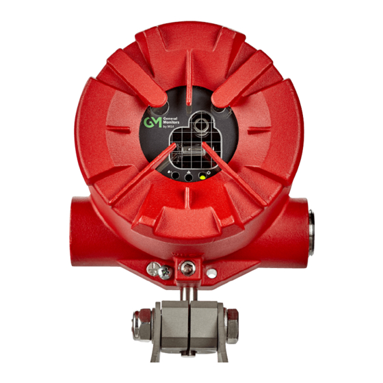
HART 7 communication • False alarm prevention Figure 2 FL500 UV/IR, FL500-H Flame Detector The FL500 is compatible with the General Monitors TA402A trip amplifier, FL802 controller, and other equipment that accepts 4 - 20 mA output. The device can be connected directly with alarm and suppression devices or switched input modules through integral relays. -
Page 8: Installation
Failure to follow these warnings can result in serious personal injury or death. Required Tools • 5 mm Allen wrench (included with the device) • Flat-blade screwdriver, maximum 1/8 in. width • No. 2 Philips screwdriver • 10 mm Allen wrench • Adjustable wrench FL500 UV/IR, FL500-H2 Flame Detector... -
Page 9: Locations
30’ 25’ 20’ 45° 90’ 0° - 45° 90’ 60° 75’ - 60° 60’ 15° 65° 50’ 40’ 30’ - 65° 50’ 40’ 30’ 30° 45° 55° 60° 65° Figure 3 Heptane Field of View FL500 UV/IR, FL500-H2 Flame Detector... - Page 10 − 45° 80’ 50’ 15° 50° 35’ − 50° 35’ 55° 65’ 45’ 30° − 55° 65’ 45’ 60° 50’ 35’ − 60° 60’ 35’ 45° 50° 55° 60° 65° Figure 4 Methane Field of View FL500 UV/IR, FL500-H2 Flame Detector...
- Page 11 − 40° 15° 50° 40’ 30’ 25’ − 50° 40’ 30’ 25’ 55° 20’ 30° − 55° 20’ 60° 30’ 20’ 40° 45° − 60° 30’ 20’ 50° 55° 60° Figure 5 Methanol Field of View FL500 UV/IR, FL500-H2 Flame Detector...
- Page 12 25’ 15° − 40° 35’ 25’ 45° 25’ 20’ − 45° 25’ 20’ 55° 30° 60’ − 55° 60’ 40° 60° 50’ 45° − 60° 50’ 50° 55° 60° Figure 6 Propane Field of View FL500 UV/IR, FL500-H2 Flame Detector...
- Page 13 30’ − 40° 40’ 30’ 15° 45° 30’ 25’ − 45° 30’ 25’ 50° 60’ 30° − 50° 60’ 60° 55’ 40° − 60° 55’ 45° 50° 55° 60° Figure 7 Ethane Field of View FL500 UV/IR, FL500-H2 Flame Detector...
- Page 14 40° 25’ − 40° 25’ 15° 45° 25’ 20’ − 45° 25’ 20’ 55° 55’ 30° − 55° 55’ 60° 45’ 40° − 60° 45’ 45° 50° 55° 60° Figure 8 Butane Field of View FL500 UV/IR, FL500-H2 Flame Detector...
- Page 15 20’ 40° 25’ 45° 60’ 20’ 20’ - 45° 60’ 25’ 20’ - 50° 20’ 20’ ± 55° 60’ 60° 50’ - 60° 50’ 15’ 65° 15’ Figure 9 Hydrogen Field of View FL500-H horizontal FL500 UV/IR, FL500-H2 Flame Detector...
-
Page 16: Mounting
General Monitors does not recommend the use of cable shoes or crimps on any junction box or housing wiring terminals. Poor crimping can cause a bad connection when temperature variations occur. Figure 10 FL500 Outline Drawing, Front View FL500 UV/IR, FL500-H2 Flame Detector... - Page 17 3 Installation Figure 11 FL500 Outline Drawing, Side View Figure 12 FL500 and Mounting Bracket, Side View Figure 13 FL500 and Mounting Bracket, Top View FL500 UV/IR, FL500-H2 Flame Detector...
-
Page 18: Wiring
If conduit is used, to prevent corrosion in the housing due to moisture or condensation, a drain loop in the conduit is recommended. For enclosure entry points, a non-hardening sealant should be used on threads. FL500 UV/IR, FL500-H2 Flame Detector... -
Page 19: Terminal Connections
To connect the wire to the terminal block, install the conductor in the connection space as shown. Use a flat-blade screwdriver to tighten the related screw terminal. Terminal Connections There are 20 terminal connections. The following sections give descriptions and specifications for each connection. FL500 UV/IR, FL500-H2 Flame Detector... - Page 20 All options can be set through Modbus, HART, or the DIP switch. Refer to Section 4.2 Changing Device Settings instructions. Alarm Low Relay Contact Relay Contact Position Relay (De-Energized) (Energized) Common Common FL500 UV/IR, FL500-H2 Flame Detector...
- Page 21 The 0 - 20 mA output is equivalent to the following analog output: Condition Modbus HART (Normal) HART (Special) Startup 0 - 0.2 mA 3.5 ±0.2 mA 1.25 ±0.2 mA Fault 0 - 0.2 mA 3.5 ±0.2 mA 1.25 ±0.2 mA FL500 UV/IR, FL500-H2 Flame Detector...
-
Page 22: Cable Lengths
Cable AWG Run (ft) Cable (mm Run (m) 9000 2.50 2750 5800 1.50 1770 3800 1.00 1160 2400 0.75 1700 0.50 Use the following cable lengths (maximum 20-ohm loop) for a 24 Vdc power supply. FL500 UV/IR, FL500-H2 Flame Detector... -
Page 23: Power Supply
Connect the cable armor to safety earth in a nonhazardous area. Connect the cable screen (drain wire) to instrument earth in a nonhazardous area. Connect the power supply OV return to instrument earth in a nonhazardous area. FL500 UV/IR, FL500-H2 Flame Detector... -
Page 24: Operation
To change device settings through the DIP switch, do the following: Use a flat-blade screwdriver to remove the screws that attach the detector head to the base assembly. Find the DIP switch. Make the applicable switch assignments. FL500 UV/IR, FL500-H2 Flame Detector... - Page 25 Alarm High Non-Latching OFF - Alarm High Latching Alarm Low Non-Latching OFF - Alarm Low Latching Alarm High Normal Energized Alarm High Normal OFF - De-Energized Alarm Low Normal Energized Alarm Low Normal OFF - De-Energized FL500 UV/IR, FL500-H2 Flame Detector...
-
Page 26: Sensitivity Check
Make sure that the batteries are fully charged and the rotary switch is set at position 4 (FL4000 position). Stand 15 - 20 ft (5 - 6 m) away from the FL500 UV/IR. Stand up to 30 ft (9 m) away from the FL500 H Point the TL105 test lamp directly at the front of the device. -
Page 27: Maintenance
5.2 Cleaning the Optical Window and Reflectors instructions. Do sensitivity checks regularly. Refer to Section 4.3 Sensitivity Check for instructions. Examine, clean the optical window, and do sensitivity checks more frequently for devices that are installed in dirty areas. FL500 UV/IR, FL500-H2 Flame Detector... -
Page 28: Cleaning The Optical Window And Reflectors
If possible, keep the device in the mold as shipped by the manufacturer. Install the red dust caps in the cable entry holes. Seal the device and a desiccant in a plastic bag. Seal the plastic bag inside another plastic bag. FL500 UV/IR, FL500-H2 Flame Detector... -
Page 29: Troubleshooting
16 mA or 20 mA, contact at device technical support for more troubleshooting. If the corrective actions recommended in the troubleshooting table do not correct operation of the device, return the device to General Monitors for repair. FL500 UV/IR, FL500-H2 Flame Detector... -
Page 30: Returning The Device For Repairs
EN 50130-4, Electromagnetic compatibility. Product family standard: Immunity requirements for components of fire, intruder, hold up, CCTV, access control and social alarm systems. British Standards Institute, London, United Kingdom, 2011. • EN 61000-6-4:2007+A1:2011, Electromagnetic compatibility (EMC). Generic standards. Emission standard for industrial environments. British Standards Institute, London, United Kingdom, 2007. FL500 UV/IR, FL500-H2 Flame Detector... -
Page 31: Specifications
Section 3.2.1 Field of View. Product Model FL500-H Device location Class I, Division 1, Groups B, C, and D Class II, Division 1, Groups E, F, and G Class III Ex db IIC T5 Gb FL500 UV/IR, FL500-H2 Flame Detector... -
Page 32: Mechanical Specifications
860 mA @ 18.5 VDC, 900 mA @ 24.0 VDC, 964 mA @ 36.0 VDC. Supply voltages are at the detector Maximum output signal load 600 ohms Output signal range 0 to 20 mA * Fault signal 0 to 0.2 mA * FL500 UV/IR, FL500-H2 Flame Detector... -
Page 33: Environmental Specifications
-67°F to 185°F (-55°C to 85°C) Storage temperature range -40°F to 185°F (-40°C to 85°C) Humidity range 0% to 95% RH noncondensing False Alarm Immunity for the FL500 UV/IR and FL500-H False Alarm Source Distance from Distance from Trouble / False... -
Page 34: Approvals
Two 25W tungsten incandescent lamps Approvals FL500 UV/IR is approved for CSA (CSA 18.70180732X), FM, ATEX (Sira 18ATEX1073X), UKCA (CSAE 21UKEX1334X), IECEx (SIR 18.0026X), INMETRO (NCC 18.0139X), DNV, EAC, Japan (CML 19JPN1315X), ESMA/EQM, HART Registered, SIL 3 and EN 54-10 (1725-CPR-E1001, 2803-CPR-E0010).
Need help?
Do you have a question about the FL500 UV/IR and is the answer not in the manual?
Questions and answers