Advertisement
Quick Links
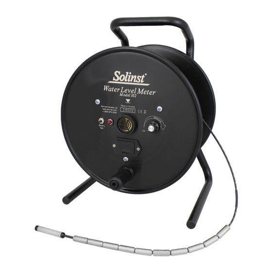
Water Level Meter On/Off Sensitivity Switch Replacement
Tools and Materials Needed
1. Sensitivity Switch and Knob Assembly (#102976), or
Sensitivity Switch (#110119)
2. Phillips Screwdriver
3. Small Flat Screwdriver
4. 10 mm (3/8") Wrench
5. Wire Cutters (if required)
6. Wire Strippers (if required)
Wire Strippers (if required)
7. Solder Wire with Flux
8. Soldering Iron
Instructions
For Mk2 Water Level Meters (Push-Release Tape Connection)
Note: Instructions for Mk1 Water Level Meters (Molex tape
connection, soldered connections to battery tray) are on Page 2.
1. Remove the battery.
2. Unscrew the small brass screw on the side of the sensitivity
knob. Remove the sensitivity knob.
3. Unscrew and remove the faceplate.
4. Press down on the white terminals of the push-release
fittings on the circuit board and pull out to remove the
tape leads.
5. Unsolder the wires at the connections to the sensitivity
switch; note the order in which they are connected.
Sensitivity
Switch
Back of Mk2 Water Level Meter Faceplate
(with new style light)
Sensitivity
Switch
Back of Mk2 Water Level Meter Faceplate
(with older style light)
Push-Release
Fittings
R4
Push-Release
Fittings
R4
High Quality Groundwater and Surface Water Monitoring Instrumentation
6. Unscrew the nut holding the sensitivity switch. Remove the
switch from the faceplate.
7. Look for the resistor labeled "R4"
on the circuit board. If this resistor
is not marked "3092", unsolder
and replace it with the one supplied
with the new sensitivity switch. You
do not need to replace the resistor
if it is already the correct one.
Note: You will need to remove the new resistor from the white
plastic before installing it.
8. Use the blue resistor supplied with the sensitivity switch to
create jumper wires between the connections on the new
sensitivity switch. Solder in place. See photos below.
9. Install the new sensitivity switch through the faceplate.
Position the three connection prongs towards the battery
drawer, slightly towards the centre of the reel. Secure using
the nut.
10. Strip the ends of the wires removed from the sensitivity
switch by 3 - 4 mm, if required. Attach the wires to the
correct positions by soldering:
The black wire on the bottom left corner of the circuit
board is connected to the centre prong on the sensitivity
switch. The other black wire is connected to the prong on
the right of the sensitivity switch. The red wire connects to
the upper terminal on the top of the switch. See photos
below (some shown separate from circuit board for clarity).
Model 101/102
Advertisement

Related Manuals for Solinst 102


Summary of Contents for Solinst 102
- Page 1 Water Level Meter On/Off Sensitivity Switch Replacement Model 101/102 6. Unscrew the nut holding the sensitivity switch. Remove the Tools and Materials Needed switch from the faceplate. 7. Look for the resistor labeled “R4” 1. Sensitivity Switch and Knob Assembly (#102976), or on the circuit board.
- Page 2 7. Use the blue resistor to make a connection between the centre and right prongs on the switch. Solder in place. See photos at top right. ® Solinst is a registered trademark of Solinst Canada Ltd. For further information contact: Solinst Canada Ltd. Printed in Canada March 6, 2018 Fax: +1 (905) 873-1992;...
Need help?
Do you have a question about the 102 and is the answer not in the manual?
Questions and answers