Advertisement
Quick Links
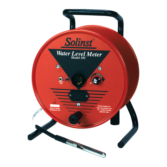
Water Level Meter Complete Electronics Replacement
Tools and Materials Needed
1. Complete Electronics Kit (#103558) Includes:
• Mk2 Circuit Board Assembly (Wiring, Sensitivity Switch and Knob,
Light and Red Lens, and Test Button)
• Sonalert (2 x Screws)
• Battery Tray (4 x Screws and Nuts)
• 9V Alkaline Battery
2. Phillips Screwdriver
3. 10 mm (3/8") Wrench
4. Wire Cutters (if required)
5. Small Flat Screwdriver (3 mm (1/10")
6. Pliers
Instructions
For Mk2 Water Level Meters (Push-Release Tape Connection)
Note: Instructions for Mk1 Water Level Meters (Molex tape
connection, soldered connections to battery tray) are on Page 2.
1. Remove the battery from the meter. Undo the three screws
holding the faceplate to the reel. Remove the faceplate.
2. Press down on the white terminals of the push-release
fittings on the circuit board and pull out to remove the tape
leads.
3. From the front of the faceplate, use the wrench to unscrew
the nut holding the test button and push the button back
out of the faceplate.
Leads From
Light Connected
To Sonalert
Back of Mk2 Water Level Meter Faceplate
with Older Style Light
4. If you have an older style light (leads connected to Sonalert
terminals – see photo above), cut the red and black wires
connected to the light, and push the light out through the
front of the faceplate.
(Page 1 of 3)
Light
High Quality Groundwater and Surface Water Monitoring Instrumentation
Complete Electronics Kit (#103558)
Back of Mk2 Water Level Meter Faceplate
with New Style Light
5. Use the Phillips screwdriver to undo the two screws from
the battery tray. Pull the quick-connect fittings off of the
terminals on the battery tray. Remove the battery tray from
the faceplate.
6. Use the small flat screwdriver to unscrew the small brass
screw on the side of the sensitivity knob. Remove the
sensitivity knob. Use the pliers to unscrew the nut holding
the sensitivity switch and remove the switch from the
faceplate.
7. Unscrew the Sonalert retaining ring from the front of the
faceplate and remove the old Sonalert and circuit board
assembly from the faceplate.
8. Insert the new battery tray through front of the faceplate.
Use the two screws (bolts and nuts where required) to
secure the tray to the faceplate.
Note: To secure the battery tray, the #4 x 1/2" Phillips Screws are for
plastic reels, while the #4-40 x 1/2" Phillips Bolts and Nuts are
for metal reels.
Model 101/102
Light
Advertisement

Subscribe to Our Youtube Channel
Related Manuals for Solinst 101


Summary of Contents for Solinst 101
- Page 1 Water Level Meter Complete Electronics Replacement Model 101/102 Tools and Materials Needed 1. Complete Electronics Kit (#103558) Includes: • Mk2 Circuit Board Assembly (Wiring, Sensitivity Switch and Knob, Light and Red Lens, and Test Button) • Sonalert (2 x Screws) •...
- Page 2 Water Level Meter Complete Electronics Replacement 9. Put the new Sonalert through the faceplate, and secure it 16. Connect the tape to the new circuit board assembly by using the retaining ring. Use the photo of the fully assembled pressing down on the white terminals on the circuit board faceplate at the bottom of the page as a reference for its and inserting the tape leads.
- Page 3 20. Reattach the faceplate to the reel using the three screws. remainder of the pins against the tape lead, so it fits easily into the terminals on the circuit board. ® Solinst is a registered trademark of Solinst Canada Ltd. For further information contact: Solinst Canada Ltd. Printed in Canada March 19, 2018 Fax: +1 (905) 873-1992;...
Need help?
Do you have a question about the 101 and is the answer not in the manual?
Questions and answers