Advertisement
Quick Links
Tools and Materials Needed
1. Required Repair Kit
2. Small Flat Screwdriver (3 mm (1/10")
3. 10 mm (3/8") Wrench
4. Wire Cutters
5. Wire Strippers
6. Solder Wire with Flux
7. Soldering Iron
Note: These instructions explain how to replace each electronic
component, either all at once or separately as required.
Overleaf are instructions to replace each component separately.
Replacing all Electronics
Complete Electronics Kit (#103558) Includes:
• Sensitivity Switch and Knob
• Test Button
• Red LED Indicator Light with Terminals
• Battery Tray and 2 Phillips Screws
• Circuit Board Assembly with Sonalert
• 9V Alkaline battery
1. Remove the battery from the Meter. Undo the three screws
holding the faceplate to the hub.
2. Remove the faceplate and disconnect the Molex connector
connecting the circuit board to the tape.
3. From the front of the faceplate, unscrew the test button and
push it out of the faceplate.
4. Push the light out of the faceplate.
5. Use the Phillips screwdriver to undo the two screws holding
the battery tray to the faceplate. Cut the red and black wires
from the back of the battery tray. Remove the battery tray.
6. Unscrew the Sonalert retaining ring from the front of
the faceplate and remove the Sonalert and Circuit Board
Assembly.
7. Use the small flat screwdriver to unscrew the small brass
screw on the side of the sensitivity knob. Remove the
sensitivity knob. Use the pliers to unscrew the nut holding
the sensitivity switch and remove the switch from the
faceplate.
8. Insert the new battery tray through the faceplate. Use the
two screws to secure the tray to the faceplate.
9. Put the new Sonalert through the faceplate, and secure it
using the retaining ring.
10. Install the new sensitivity switch, light, and test button in the
faceplate.
11. Solder the wires from the new circuit board assembly to
the correct connections on the test button, battery tray
and sensitivity switch. Use steps 12 - 17, along with the
diagram above, as a reference.
12. The red wire labeled B+ on the circuit board is connected to
the positive terminal of the battery tray.
(Page 1 of 2)
(108429)
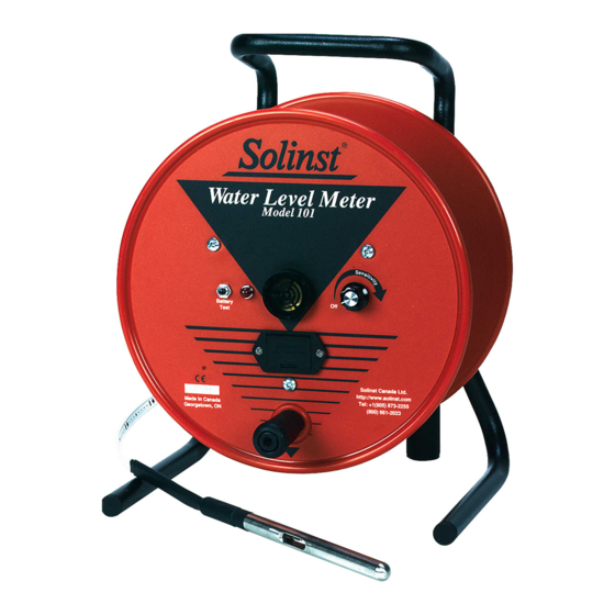
Water Level Meter Complete Electronics Replacement
High Quality Groundwater and Surface Water Monitoring Instrumentation
Sonalert
Back of
Circuit Board
(wires connected
to other side)
B
Molex
Connector
Circuit Board Showing Wire Connections
13. The other two red wires on the right side of the circuit board
are connected to the first two connections on the sensitivity
switch.
14. The black wire on the right side of the circuit board is
connected to the third terminal on the sensitivity switch.
15. The black wire furthest left on the circuit board is attached
to the terminal on the top of the sensitivity switch.
Note: There will be a black wire connecting the battery to the top of
the sensitivity switch. The new circuit board assembly comes
with a separate replacement wire.
16. The other black wire connected to the top of the sensitivity
switch is connected to the negative terminal on the battery
tray.
17. The red wire closest to the center of the circuit board is
connected to the positive terminal of the test button, and the
black wire labeled B on the circuit board is connected to the
negative terminal on the test button.
18. Place the new circuit board assembly over the connections
to the Sonalert and attach the wires from the light to the
Sonalert using the two screws through the circuit board.
19. Connect the Molex connector from the new circuit board to
connector on the tape. Install the new battery.
20. With the Probe in a glass of tap water, turn the Water Level
Meter to the 'ON' position. If the connections are correct
the buzzer and light will activate. If the buzzer or light do
not activate, check the polarity of the battery and Molex
connector, and the soldered connections.
21. Reattach the faceplate to the reel using the three screws.
Model 101/102
Test Button
Light
Battery
Tray
B+
Sensitivity
Switch
Advertisement

Related Manuals for Solinst 101


Summary of Contents for Solinst 101
- Page 1 Water Level Meter Complete Electronics Replacement Model 101/102 Tools and Materials Needed 1. Required Repair Kit 2. Small Flat Screwdriver (3 mm (1/10") Test Button 3. 10 mm (3/8") Wrench Light 4. Wire Cutters 5. Wire Strippers Sonalert 6. Solder Wire with Flux 7.
- Page 2 7. Attach the wires to the correct positions by soldering. Use the three screws. Replace the battery. the diagram above as a reference. For further information contact: Solinst Canada Ltd. Printed in Canada November 21, 2012 Fax: +1 (905) 873-1992; (800) 516-9081 Tel: +1 (905) 873-2255; (800) 661-2023...
Need help?
Do you have a question about the 101 and is the answer not in the manual?
Questions and answers