Advertisement
Tools and Materials Needed
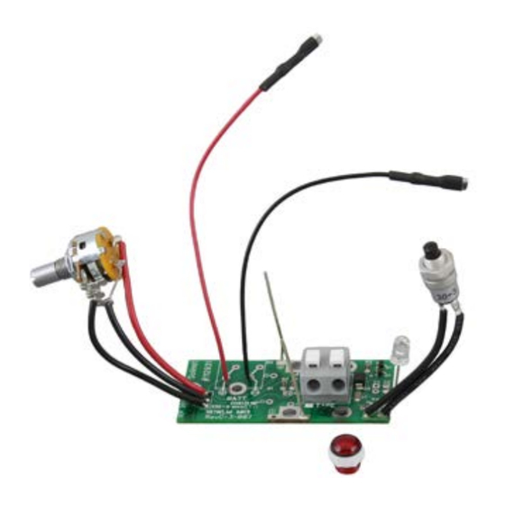
1. Mk2 Circuit Board Assembly (#102977) Includes:
• Wiring, Sensitivity Switch and Knob, Light and Red Lens, and Test Button
2. Phillips Screwdriver
3. 10 mm (3/8") Wrench
4. Wire Cutters (if required)
5. Small Flat Screwdriver (3 mm (1/10")
6. Pliers
Instructions
For Mk2 Water Level Meters (Push-Release Tape Connection)
Note: Instructions for Mk1 Water Level Meters (Molex tape
connection, soldered connections to battery tray) are on Page 2.
1. Remove the battery. Unscrew the three screws and remove
the faceplate.
2. Press down on the white terminals of the push-release
fittings on the circuit board and pull out to remove the tape
leads.
3. Pull the quick-connect fittings off of the terminals on the
battery tray.
4. From the front of the faceplate, use the wrench to unscrew
the nut holding the test button and push the button back
out of the faceplate.
Leads From
Light Connected
To Sonalert
Back of Mk2 Water Level Meter Faceplate
with Older Style Light
5. If you have an older style light (leads connected to Sonalert
terminals – see photo above), cut the red and black wires
connected to the light, and push the light out through the
front of the faceplate.
6. Use the small flat screwdriver to unscrew the small brass
screw on the side of the sensitivity knob. Remove the
sensitivity knob. Use the pliers to unscrew the nut holding
the sensitivity switch and remove the switch from the
faceplate. Save the knob and screw to be used with the
new sensitivity switch.
(Page 1 of 3)
Water Level Meter Circuit Board Replacement
Light
High Quality Groundwater and Surface Water Monitoring Instrumentation
7. Remove the two screws to disconnect the old circuit board
assembly from the Sonalert. Remove the old circuit board.
8. Loosen the Sonalert retaining nut on the front of the
faceplate, so you can reposition the Sonalert as shown in
the photo below (negative terminal next to the battery tray).
Sonalert
Back of Mk2 Water Level Meter Faceplate with New Style Light
9. If you had an older style light (or the lens needs replacing)
insert the new red lens through the opening in the faceplate
and secure using the white nut.
10. Place the circuit board assembly in position on top of the
Sonalert, ensuring the sides marked +ve and -ve are lined
up with the corresponding terminals on the Sonalert and
the light seated in the lens.
11. Install the two screws into the Sonalert terminals. Do not
tighten. Wrap the two bare wires from the circuit board
around the screws, between the screw head and Sonalert
terminals. Start by bringing the wires underneath the
screws (see photo below). Tighten the two screws.
Model 101/102
Light
Battery
Tray
Advertisement
Table of Contents

Related Manuals for Solinst 101


Summary of Contents for Solinst 101
- Page 1 Water Level Meter Circuit Board Replacement Model 101/102 Tools and Materials Needed 1. Mk2 Circuit Board Assembly (#102977) Includes: • Wiring, Sensitivity Switch and Knob, Light and Red Lens, and Test Button 2. Phillips Screwdriver 3. 10 mm (3/8”) Wrench 4.
- Page 2 Water Level Meter Circuit Board Replacement Instructions 12. Insert the test button through the opening in the faceplate, and secure it in place using the nut. For Mk1 Water Level Meters (Molex Tape Connection) 13. Insert the sensitivity switch through the faceplate with the three connection prongs positioned towards the battery Note: Instructions for Mk2 Water Level Meters are on Page 1 drawer, slightly towards the centre of the reel.
- Page 3 19. Reattach the faceplate to the reel using the three screws. Remove the Pins from the Tape Molex Connector ® Solinst is a registered trademark of Solinst Canada Ltd. For further information contact: Solinst Canada Ltd. Printed in Canada March 19, 2018 Fax: +1 (905) 873-1992;...
Need help?
Do you have a question about the 101 and is the answer not in the manual?
Questions and answers