Advertisement
Quick Links
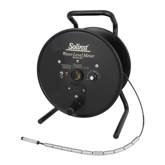
Indicator Light
Battery Test
Button
Handle
Front View
Equipment Check
1. Turn sensitivity dial fully clockwise.
Notes: 1. Clockwise rotation of sensitivity dial turns meter on and
increases sensitivity.
2. Always set dial to highest sensitivity position, then
decrease if necessary.
2. Depress the Battery Test button to test the battery and main
circuitry (does not test the cable or probe).
3. Submerse the probe in tap water. This completes the circuit
and activates the buzzer and light.
The Tape Guide
The Tape Guide has been designed to:
• Improve accuracy when reading water levels,
• Easily obtain repeatable measurements,
• Prevent cable damage on well casing,
• Allow the cable and probe to hang straight from the side
of the well.
1. Fit the small end of the Tape Guide onto the edge of well
casing 2" dia. or larger.
2. For small reels, insert the leg of the Water Level Meter into
the hole on the Tape Guide and rest the Water Level Meter
on the side of the well casing. (See diagram at right).
3. To store the Tape Guide after taking water level
measurements, simply clip it onto the support bracket
located on the back of the Water Level Meter.
(Page 1 of 2)
Water Level Meter Operating Instructions
Buzzer
(Sonalert)
On/Off
Sensitivity Dial
Battery Drawer
Measurement Point
Insert Water Level
Meter leg through
hole
Fit onto well casing
High Quality Groundwater and Surface Water Monitoring Instrumentation
Probe Holder
Water Level Measurements
1. The zero measurement point on both P4 and P10 Probes is
near the tip.
2. For ease of operation the Tape Guide can be used to support
the Water Level Meter. (See diagram below).
3. Feed the cable into the well. The light and buzzer activate
when the probe tip enters water. To ensure accuracy, lower
and raise the probe a few times and then record the depth
measurement from the cable at the top of the well.
4. When using the Tape Guide, the measuring point is offset
from the top of casing. To adjust your measurements to the
top of the casing, simply subtract the amount indicated on
the front of the Tape Guide (ie 6 cm or 2/10 ft)
Model 102
Tape Guide
Brake
Back View
Tape Guide:
prevents cable from
scraping the top
edge of well casing
Water Level Meter:
anchored to the well
casing with the tape guide
for stable operation (small
reels only).
High quality
polyethylene jacketed
cable hangs straight
in the well for
accurate water level
measurements
Segmented Weights
make P10 Probe
easier to handle.
Advertisement

Related Manuals for Solinst 102


Summary of Contents for Solinst 102
- Page 1 Water Level Meter Operating Instructions Model 102 Tape Guide Buzzer Indicator Light (Sonalert) Probe Holder Battery Test Button On/Off Sensitivity Dial Brake Battery Drawer Handle Front View Back View Water Level Measurements Equipment Check 1. The zero measurement point on both P4 and P10 Probes is 1.
-
Page 2: Troubleshooting
(Contact Solinst) Disconnected wire inside probe. Contact Solinst to obtain parts/repair instructions. Instrument Water in probe. Probe may be Contact Solinst for instructions to clean or replace continuously sounds dirty which could interfere with the probe. after being immersed the circuit connection.
Need help?
Do you have a question about the 102 and is the answer not in the manual?
Questions and answers