iSMA -B-AAC20 User Manual
Sedona modbus
Hide thumbs
Also See for iSMA-B-AAC20:
- User manual (49 pages) ,
- User manual (16 pages) ,
- User manual (7 pages)

Related Manuals for iSMA iSMA-B-AAC20


Summary of Contents for iSMA iSMA-B-AAC20
- Page 1 User Manual Sedona Modbus Global Control 5 Sp. z o.o. Warsaw, Poland www.gc5.pl...
-
Page 2: Table Of Contents
1 Introduction..........................4 1.1 Revision history ........................ 4 2 Sedona Modbus ........................4 3 Installing iSMA Modbus kits ....................7 4 Modbus Async Network kit ....................8 4.1 Modbus Async license and limitation ................8 4.2 Modbus Async Network ....................8 4.3 Modbus Async Device .................... - Page 3 Modbus 8.3.2 DO components ....................46 8.3.3 UI components ....................47 8.3.4 AO components ....................48 8.3.5 iSMA Folder ......................49 9 iSMA-B-AAC20 Modbus table....................50 Version 1.3 www.gc5.pl Page 3 / 55...
-
Page 4: Introduction
Modbus 1 Introduction This manual contains information about Modbus protocols in iSMA-B-AAC20 controller. The iSMA-B-AAC20 controller support following types of Modbus: • Modbus ASCII/RTU • Modbud TCP • Modbus TCP Slave 1.1 Revision history Date Description • First edition 28.08.2015... - Page 5 Modbus Coil status - Or simply “coils”: single-bit flags that represent the status of Digital (Boolean) Outputs of the slave, that is, On/Off output status. A Modbus Master can both read from and write to coils. Input status - Or simply “inputs”: single-bit flags that represent the status of Digital (Boolean) Inputs of the slave, that is, On/Off output status.
- Page 6 Modbus Modbus data addresses A Modbus device is not required to contain all four groups of data. For example, a metering device may contain only holding registers. However, for each data group implemented, an “address convention” is used. The requests for data (made to a device) must specify a data address (and range) of interest.
-
Page 7: Installing Isma Modbus Kits
Modules - extension of Modbus Async Netwok to serve iSMA MIX, Wireless and MINI devices using Modbus Async protocol, iSMA Modbus TCP Network - to serve Modbus TCP Master of the iSMA-B-AAC20 device using IP connection, iSMA Modbus TCP Slave Network - to serve Modbus TCP Slave of the iSMA-B-AAC20 controller using IP connection. -
Page 8: Modbus Async Network Kit
Modbus 4 Modbus Async Network kit This section provides a collection of procedures to use the iSMA-B-AAC20 Modbus drivers to build networks of devices with Modbus points. The iSMA-B-AAC20 controller has one RS485 port which can be used as a Modbus RTU / ASCII Master. - Page 9 Modbus Figure 2 – Modbus Async Network component Modbus Async Network component has the following slots: Status – Network status, available states: OK – Network is working properly, Disabled – Network is disable (Slot “Enable” is in false), OK some device/point down – error in device or points.
- Page 10 Modbus Write On Start – Do write action in device „Writable” components in Modbus Network after reset or power up, Write On Up - Do write action in device „Writable” components in Modbus Network after restore the connection with Modbus device, Write On Enable - Do write action in device „Writable”...
-
Page 11: Modbus Async Device
Modbus 4.3 Modbus Async Device ModbusAsyncDevice is a component which is responsible for servicing physical device connected to Modbus Network. The device as Modbus Master to all other Modbus devices on the attached RS485 port. Each device is represented by a Modbus Device, and has a unique Modbus address (1 to 247), as well as other Modbus config data and starting addresses for Modbus data items (coils, inputs, input registers, holding registers). - Page 12 Modbus Modbus Async Device has the following slots: Status – Device actual status (read Only), can take the following states: OK – Device is working properly, Disable – Device is disable (Slot “Enable” is in false), Down – Device is not available, Ok, some points down/error –...
-
Page 13: Modbus Data Points
Modbus 4.4 Modbus data points In Modbus protocol each device has implemented Modbus table. Sedona has 5 components to read/write data from this table: Boolean Point – Read Boolean value (Modbus command 0x02), Boolean Writable – Read/write Boolean value (Modbus command 0x05), Numeric Point –... -
Page 14: Modbus Async Boolean Writable
Modbus Boolean Point component has the following slots: Status – Point status, available states: OK – Point is working properly, Disabled – Point is disable (Slot “Enable” is in false), Down/Timeout – Point is not available, Device Down – Device is not available, Wrong address format –... - Page 15 Modbus Figure 5 - Modbus Async Boolean Writable component Modbus Async Boolean Writable component has the following slots: Status – Point status, available states: OK – Point is working properly, Disabled – Point is disable (Slot “Enable” is in false), Down/Timeout –...
-
Page 16: Modbus Async Numeric Point
Modbus Trigger - Remote force sending trigger (on rising edge), Out – Output slot, current value of read/write registry, In – Input slot. 4.4.3 Modbus Async Numeric Point Modbus Async Numeric Point is a component which is responsible for reading numeric values from the device. -
Page 17: Modbus Async Numeric Writable
Modbus Network disabled – Modbus Network is disabled. Fault Cause – Fault cause description, Fault Status – Point error status (true – point read error), Enable – Point enable/disable („true”- Point enable, „false”- Point disable), Address Format – Register address format, available options: Modbus, Decimal, Address –... - Page 18 Modbus Figure 7 - Modbus Async Numeric Writable component Modbus Async Numeric Writable component has the following slots: Status – Network status, available states: OK – Point is working properly, Disabled – Point is disable (Slot “Enable” is in false), Down/Timeout –...
-
Page 19: Modbus Async Numeric Multi Point
Modbus Trigger – Remote force sending trigger (on rising edge), Out – Output slot, current value of device registry, In – Input slot. 4.4.5 Modbus Async Numeric Multi Point Modbus Async Numeric Multi Point is a component which is responsible for reading up to 8 16-bits registers from the device in one message. -
Page 20: Modbus Folder
Modbus Modbus Async Numeric Multipoint component has the following slots: Status – Point status, available states: OK – Point is working properly, Disabled – Point is disable (Slot “Enable” is in false), Down/Timeout – Point is not available, Device Down – Device is not available, Wrong address format –... -
Page 21: Modbus Tcp Network Kit
Modbus 5 Modbus TCP Network kit The iSMA-B-AAC20 controller has implemented Modbus TCP protocol. It means that controlled as a Master device can read/write data to Slave devices using IP connection. 5.1 Modbus TCP license and limitation In controller without Modbus license there are available 15 data points. Licence can be expanded up to 500 points by purchasing Modbus license. - Page 22 Modbus Figure 9 - Modbus TCP Network component Modbus TCP Network component has following slots: Status – Network status, available states: OK – Network is working properly, Disabled – Network is disable (Slot “Enable” is in false), OK some device/point down – error in device or points.
-
Page 23: Modbus Tcp Device
Modbus Fast Rate – Time between messages in „Fast” mode poll frequency, Normal Rate – Time between messages in „Normal” mode poll frequency, Slow Rate – Time between messages in „Slow” mode poll frequency, Average Poll Time – Average time for sending/receiving one message, Busy Time –... - Page 24 Modbus Figure 10 - Modbus TCP Device component Modbus TCP Device has the following slots: Status – Device actual status (read Only), can take the following states: OK – Device is working properly, Disable – Device is disable (Slot “Enable” is in false), Down –...
-
Page 25: Modbus Tcp Data Points
Modbus Ping Type – Tested register type: Input/Holding, Byte Order – Byte order reading 32-bit: 3210 (Big endian), 1032 (Little endian). 5.4 Modbus TCP data points In Modbus protocol each device has implemented Modbus table. Sedona has 5 components to read/write data from this table: Boolean Point –... - Page 26 Modbus Figure 11 - Modbus TCP Boolean Point component Modbus TCP Boolean Point component has the following slots: Status – Network status, available states: OK – Point is working properly, Disabled – Point is disable (Slot “Enable” is in false), Down/Timeout –...
-
Page 27: Modbus Tcp Boolean Writable
Modbus 5.4.2 Modbus TCP Boolean Writable Modbus TCP Boolean Writable is a component which is responsible for sending and reading Boolean values from device. The component has the following actions available under the right mouse button: Set True/Set False – Write value to slot In and sends it to the device (not active when slot In have connected link), Write –... -
Page 28: Modbus Tcp Numeric Point
Modbus Device disabled - Device is disabled, Network disabled – Modbus Network is disabled. Fault Cause – Fault cause description, Fault Status – Point error status (true – point read/write error), Enable – Point enable/disable („true”- Point enable, „false”- Point disable), Address Format –... - Page 29 Modbus Figure 13 - Modbus TCP Numeric Point component Modbus TCP Numeric Point component has the following slots: Status – Network status, available states: OK – Point is working properly, Disabled – Point is disable (Slot “Enable” is in false), Down/Timeout –...
-
Page 30: Modbus Tcp Numeric Writable
Modbus Data Type – Reading registry data type, available options: Int – 16-bits, Long – 32-bits, Float – 32-bits folat-point, SInt – 16-bits with sing, Slong – 32-bits with sing, Out – Current value of read registry. 5.4.4 Modbus TCP Numeric Writable ModbusClientNumericWritable is a component which is responsible for sending and reading Numeric values from device. -
Page 31: Modbus Tcp Numeric Multi Point
Modbus Device Down – Device is not available, Wrong address format – Incorrect address format according to address format setting slot, Device disabled - Device is disabled, Network disabled – Modbus Network is disabled. Fault Cause – Fault cause description, Fault Status –... - Page 32 Modbus Figure 15 - Modbus TCP Numeric Multipoint property sheet view Modbus TCP Numeric Multipoint component has following slots: Status – Point status, available states: OK – Point is working properly, Disabled – Point is disable (Slot “Enable” is in false), Down/Timeout –...
-
Page 33: Modbus Folder
Modbus Number Of Registers – Number of reading register in one messages, Out – Current value of read registry. 5.5 Modbus folder ModbusFolder is a component which groups and organizes Modbus points components. Because of Sedona components name are limited to 7 characters, ModbusFolder has Description Slot where we can us up to 32 characters. -
Page 34: Modbus Tcp Slave Network Kit (Ip Module)
0 to 999 (decimal numeration) are reserved for controller registers. To see list of registers and registers parameters go to iSMA-B-AAC20 Modbus Table chapter. Addresses from 1000 – 2999 are free to use and can be adopted in user application. -
Page 35: Modbus Tcp Slave Network
Modbus 6.1 Modbus TCP Slave Network Modbus TCP Slave is always enable and to read controller registers it doesn’t have to be configured. Modbus TCP Slave network is use only for changing parameters (parameters can by changed also from controller configuration web page) and to set up user registers. -
Page 36: Boolean Value
Modbus BooleanValue – Read/Write Boolean values, NumericValue – Read/Write Numeric values. WARNING! There is only one table for booth values. Data points addresses are assigned manually, please take care not to override one register from many components. WARNING! BooleanValue and NumericValue have read and write function. To read only use only Out slot, In slot live not connected with null (for Boolean) or nan (for numeric) value. -
Page 37: Numeric Value
Modbus Modbus TCP Slave Boolean Value component has the following slots: Status – Point status, Fault Cause – Fault cause description, Description – Point description label up to 32 characters, Address Format – Modbus addressing format: Modbus/Decimal Address – Register address (from0 to 65535), Bit –... - Page 38 Modbus Figure 19 - Modbus TCP Slave Numeric value component Version 1.3 www.gc5.pl Page 38 / 55...
-
Page 39: Modbus Folder
Modbus Modbus TCP Slave Numeric Value component has the following slots: Status – Point status, Fault Cause – Fault cause description, Description – Point description label up to 32 characters, Address Format – Modbus addressing format: Modbus/Decimal Address – Register address (from0 to 65535), Data Type –... -
Page 40: Modbus Rs 485 Slave Device (Com1)
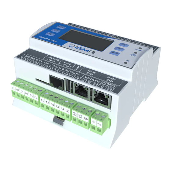
Modbus 6.4 Modbus RS 485 Slave Device (COM1) iSMA-B- AAC20 controller can be also Slave Device working on RS485 bus connection. To connect iSMA-B-AAC20 controller to RS485 bus you must use Com1 port with RJ12 connector. RJ12 connector is located between SD card and USB slot. The Modbus RS485 Slave use the same Modbus table as Modbus TCP Slave. - Page 41 Modbus Figure 20 - RJ12 connector pins numbers RJ12 pins description: Pin1 – G0 potential, (SD card side), Pin2 – RS485 – (B), Pin3 – RS485 + (A), Pin4 – G0 potential, Pin5 – G potential, directly connecter to G terminal in power supply, Pin6 - G potential, directly connecter to G terminal in power supply (USB side).
-
Page 42: Gateway Mode
Modbus 7 Gateway mode The iSMA-B-AAC20 controller can also work as a Modbus TCP/RS485 gateway. Default, this option is enable until there is no ModbusAsyncNetwork component in Sedona application or the component is disable (ModbusAsyncNetwork -> Enable slot in false state). -
Page 43: Isma Module
Modbus 8 iSMA Module iSMA Modules are a Modbus Async Network extension to serve iSMA devises from MIX, MINI and wireless series using Modbus protocol. iSMA Modules kit contains prepared components for serving physical inputs, outputs and configuration parameters. iSMA Modules are an extension of Modbus Async Network designed to easily serve iSMA devices series like MIX modules, MINI modules and Wireless Module using Modbus ASCII/RTU protocol. -
Page 44: Isma Device
Figure 22 – iSMA Module Device component 8.2 iSMA Device config component iSMA config is a special component dedicated to set up iSMA series device parameters. Adding and removing config component is done by Module Type slot in iSMA Device component. -
Page 45: Isma Io Components
Wireless series. iSMA Module kit contains of components to serve all input/output. 8.3.1 DI components In iSMA Module kit are available two types of component to read device Digital Inputs: DI – to read individual Digital Inputs (input number is selected in component property sheet), DI_ALL to read all Digital Inputs using one register. -
Page 46: Do Components
Figure 24 – iSMA Module Digital Input components 8.3.2 DO components In iSMA Module kit are available two types of component to read/write device Digital Outputs: DO – to read/write individual Digital Outputs (output number is selected in component property sheet), DO_ALL to read all Digital Outputs using one register. -
Page 47: Ui Components
Figure 25 - iSMA Module Digital Output components 8.3.3 UI components In iSMA Module kit are available five types of component to read device Universal Inputs: UI_Temp – to read temperature value from NTC sensor connected to Input, UI_Res - to read resistance value between Universal Input and G0, UI_Volt –... -
Page 48: Ao Components
0 value. 8.3.4 AO components In iSMA Module kit are available two types of component to read/write device Analog Outputs: AO_Volt – to set up voltage signal (0 – 10000mV) on Analog Output, AO_PWM –... -
Page 49: Isma Folder
8.3.5 iSMA Folder iSMAFolder is a component which groups and organizes iSMA Module IO points components. Because of Sedona components name are limited to 7 characters, ModbusFolder has Description Slot where we can use up to 32 characters. -
Page 50: Isma-B-Aac20 Modbus Table
Modbus 9 iSMA-B-AAC20 Modbus table Modbus Register name Access Description Address Addr Adr. 40001 0x00 VERSION AND TYPE Read Only Controller firmware version and type 40002 0x01 HARDWARE VERSION Read Only Controller Hardware version Read Controller Modbus TCP/IP Slave and... - Page 51 Modbus Modbus Register name Access Description Address Addr Adr. 30081 0x50 UNIVERSAL INPUT VOLTAGE 6 Read Only 30082 0x51 UNIVERSAL INPUT TEMPERATURE 6 Read Only 30083 0x52 UNIVERSAL INPUT VOLTAGE 7 Read Only 30084 0x53 UNIVERSAL INPUT TEMPERATURE 7...
- Page 52 Modbus Modbus Register name Access Description Address Addr Adr. 30118 0x75 RESISTIVE INPUT 8 MSB Read Only Read & 40121 0x78 VALUE OF ANALOG OUTPUT 1 Write Read & 40122 0x79 VALUE OF ANALOG OUTPUT 2 Write Read &...
- Page 53 Modbus Modbus Register name Access Description Address Addr Adr. Read & State of Analog Outputs assigned at the DEFAULT STATE OF ANALOG 40144 0x8F Write start of the module and watchdog reset. OUTPUTS (DIGITAL) Memory The default value is 0.
- Page 54 Modbus Modbus Register name Access Description Address Addr Adr. Pt1000 Ni1000 +128 Voltage measurement off Read & UNIVERSAL INPUT 8 40158 0x9D Write CONFIGURATION Memory Read & FILTER TIME CONSTANT 40159 0x9E Write Filter time constant, expressed in seconds...
- Page 55 Modbus Modbus Register name Access Description Address Addr Adr. Memory PWM 1Hz PWM 10Hz Read & PWM 100Hz 40171 0xAA ANALOG OUTPUT 4 CONFIGURATION Write Memory PWM 0.1Hz Read & PWM 0.01Hz 40172 0xAB ANALOG OUTPUT 5 CONFIGURATION Write Memory Read &...
Need help?
Do you have a question about the iSMA-B-AAC20 and is the answer not in the manual?
Questions and answers