iSMA -B-MAC36NL Installation And Startup Manual
Master application controller
Hide thumbs
Also See for iSMA-B-MAC36NL:
- User manual (51 pages) ,
- User manual (24 pages) ,
- User manual (33 pages)

Related Manuals for iSMA iSMA-B-MAC36NL


Summary of Contents for iSMA iSMA-B-MAC36NL
- Page 1 User Manual Installation and Start-up Guide Global Control 5 S.A. Warsaw, Poland www.globalcontrol5.com...
-
Page 2: Table Of Contents
User Manual Table of Contents 1 Introduction..........................3 1.1 Revision History ........................ 3 1.2 Safety Rules........................4 1.3 Overview ..........................4 1.4 Key Features: ........................5 1.5 Technical Specification ....................6 1.6 Software License Notice ....................7 1.7 Dimensions ........................8 2 Hardware Specification ...................... -
Page 3: Introduction
User Manual 1 Introduction 1.1 Revision History Date Description 01.10.2018 First edition 10.12.2018 Data Recovery Service, Support of the Niagara 4.6 and later 01.04.2019 HDMI Support, Restore to factory defaults 31.10.2019 Updated Universal Input supported sensor list Support of Niagara 4.8 31.03.2020... -
Page 4: Safety Rules
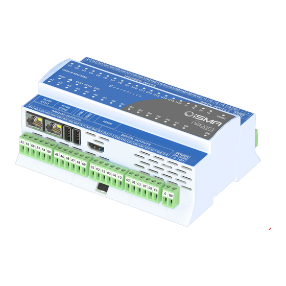
1.3 Overview iSMA-B-MAC36NL is a compact Master Application Controller with built-in different types of I/O and operating in the Niagara Framework environment. Using the specific local I/O set 16x UI, 8x AO, 4x DI and 8x DO allows to use the device in different applications. The controller provides control, data logging, alarming, scheduling, integration, and visualisation. -
Page 5: Key Features
• Built-in web server provides graphical user interface available from the web browser level • SD card to collect real-time data, history logs, and alarms • Hardware replacement by SD Card • Different licensing models for various application types Figure 1. iSMA-B-MAC36NL Key Features Version 1.6 www.globalcontrol5.com Page 5 / 50... -
Page 6: Technical Specification
User Manual 1.5 Technical Specification Voltage 24 V AC/DC ± 20% isolated Power Supply Power consumption 14 W @ 24 V DC; 24 VA @ 24 V AC Temperature input Measurement with attached RTDs • Accuracy ±0,1˚C • For sensor Pt1000 and Ni1000 use 16-bit •... -
Page 7: Software License Notice
User Manual Baud rate From 2400 to 115,200 Address 1 to 247 Voltage 30 V M-Bus Interface (optional) Max. current load 30mA No. of devices Up to 20 Baud rate 300-19200 Max. cable length 350 m Niagara support From N4.8 (OS .1147) -
Page 8: Dimensions
The corresponding open-source code of this product can be obtained by sending an e-mail rd@gc5.pl This offer is valid to anyone in receipt of this information. 1.7 Dimensions Figure 2. iSMA-B-MAC36NL Dimensions [mm] Version 1.6 www.globalcontrol5.com Page 8 / 50... -
Page 9: Hardware Specification
User Manual 2 Hardware Specification 2.1 Terminals and Internal Connection Diagram The iSMA-B-MAC36NL controller is supplied by 24 V AC/DC. The power supply block is separated. The grounding pin located next to power supply terminals must be connected to the ground. -
Page 10: Power Supply Connection
User Manual 2.2 Power Supply Connection The device is designed to work with 24 V AC/DC separated power supply. Figure 4. 24 V AC/DC power supply connection 2.2.1 Earth Grounding Earth grounding protects from electrostatic discharge or other forms of EMI. Connecting the controller’s ground spade lug to nearby earth ground is possible in hardware versions below... -
Page 11: Rs485 Grounding And Shielding
In case of an RS485 twisted pair cable, the termination is typically 120 Ω. In the iSMA-B-MAC36NL version there is a built-in 3-position switch on the back side of the device (access after removing the back cover), which is dedicated to connecting termination resistor and/or biasing resistors. - Page 12 User Manual Figure 6. Switch for termination and biasing for the base (on left) and optional extension port (on right) Switch position Biasing Termination 120 Ω + Biasing NONE Table 3. Switch Termination and biasing Version 1.6 www.globalcontrol5.com Page 12 / 50...
- Page 13 User Manual If the switch is in the END position, it connects the termination resistor 120 Ω and biasing resistors 680 Ω (pull-down to ground SG and pull-up to +5 V DC) to the RS485 bus. Instead of using additional resistors, the termination and biasing can easily be done by a simple switch activation.
-
Page 14: M-Bus Connection
Figure 8. RS485 network biasing 2.3.3 M-Bus Connection M-Bus devices can be connected directly only to the iSMA-B-MAC36NL-M, the controller’s hardware version with the M-Bus interface (max. 20 devices). Figure 9. M-Bus connection Version 1.6... -
Page 15: Detection Of The Device Extension
User Manual 2.4 Detection of the Device Extension Starting from the iSMA-B-MAC36NL hardware version 2.1 and up, the device extension is detected automatically and displayed for information in the Products field of the Workbench platform. 2.5 LED Indicators The device is equipped with LEDs for quick status checking and diagnostics: Figure 10. -
Page 16: Mini Usb
The mini USB port is dedicated to debugging connection through the console. A description, how to connect to the system console, is included in Chapter 3.6 Connection to Console. Figure 11. LEDs on the front panel of iSMA-B-MAC36NL. Version 1.6 www.globalcontrol5.com Page 16 / 50... -
Page 17: Local I/O
User Manual 2.7 Local I/O The iSMA-B-MAC36NL has built-in different types of I/O. The specific local I/O set 16x UI, 8x AO, 4x DI, and 8x DO allows to use the device in different applications. For the detailed description of the local I/O set please refer to the Local IO User Manual, available at the support.gc5.pl. - Page 18 SD card from one unit to another (the microSD card is not assigned to the particular hardware iSMA-B-MAC36NL unit). For example, the SD card may be removed from a unit that suffered a hardware failure and used it in a replacement unit.
-
Page 19: Factory Settings
Note: In Niagara 4.6 and later versions, the user is requested to change the factory platform credentials at the first platform logging. Note: Starting from the iSMA-B-MAC36NL hardware version 2.1, the passphrase is saved on the SD card. For controllers firstly commissioned in the Niagara 4.4 version, once the Niagara Framework is upgraded to 4.8 version or later, the passphrase resets to default “niagara”;... -
Page 20: First Login To The Controller Platform In Workplace
User Manual Figures 13 and 14. Passphrase reset 3.4 First Login to the Controller Platform in Workplace WARNING! It is highly advisable to install the Data Recovery Service with the first commissioning of the controller. See more in the point 3.10. - Page 21 User Manual Figure 15. First login view If the Change Platform Defaults Wizard displays, click Next to step through creating a system passphrase, creating a new platform account, and removing the default platform account, as shown below. Version 1.6 www.globalcontrol5.com...
- Page 22 User Manual Version 1.6 www.globalcontrol5.com Page 22 / 50...
-
Page 23: Tcp/Ip Configuration
User Manual Figures 16, 17, and 18. First login views Click Finish to complete these changes. The system completes making the connection between the host and Workbench, and displays the Nav Container View. 3.5 TCP/IP Configuration A TCP/IP Configuration is one of several platform views. Typically, it is used to initially configure a remote controller’s TCP/IP settings. - Page 24 As shown above, each Interface has the following properties at the top: • ID: a read-only OS identifier for the hardware interface, such as “eth0” for the iSMA-B- MAC36NL controller, or, for a Windows platform, either a 128-bit GUID (globally unique Version 1.6...
- Page 25 (platform daemon and station) responds to IPv6 requests, that is, creates IPv6 server sockets (daemon) and IPv6 fox multicast sockets. If connected to the iSMA-B-MAC36NL controller, the DNS and gateway settings are also “host- level” parameters in the TCP/IP Configuration view, as shown below.
- Page 26 Note: For a Windows-based host, DNS and gateway settings are available under each Interface section. Figure 22. DNS gateway view The available fields for iSMA-B-MAC36NL controllers are as follows: • DNS Domain: the TCP/IP Domain Name System (DNS) domain this host belongs to, if used.
-
Page 27: Connection To The Console
User Manual Reboot the controller for the changes to take effect. 3.6 Connection to the Console The console is used for service purposes, including registration of system logs, which can be analyzed by the support department. Note: With Niagara 4.8 and up, the logs are saved directly into the user home directory, which allows for historical reviews. -
Page 28: Controller System Update
User Manual Figure 24. COM port settings in PuTTY • In the Category tree click “Session”, and choose “Connection type” as a “Serial”. • Click the “Open” button at the bottom of the PuTTY window. • There are the system logs and collect dumps for service purposes by the GC5 support department. - Page 29 User Manual Figure 25. Update package file The package contains elements of the system that will be updated as new elements of the system, or as newer versions of Niagara, operating system, modules, and the Clean dist file. After unpacking, run the bat file.
- Page 30 User Manual Installing the update After logging in to the Platform of the controller, right click on the Platform, and run the Commissioning Wizard process. Passing through the next wizard windows, an additional dialog window will appear, informing about the need to update the appropriate controller system component (OS, NEL, JVM).
-
Page 31: Restore Controller To The Default State
Wait for the reboot to complete. Note: iSMA-B-MAC36NL from Niagara 4.4 to 4.8 can be restored to 4.4 version of Niagara (cleanDist V1.x). Controllers with Niagara 4.8 and up can be restored to 4.8 version of Niagara (cleanDist V2.x). -
Page 32: Restore Controller To The Factory Default
3.9 Restore Controller to the Factory Default In case the username and/or password to the platform have been lost, or the connection to the controller cannot be established because the IP address of the iSMA-B-MAC36NL controller remains unknown, there is a function to restore factory values. - Page 33 User Manual Figure 31. Top cover After removing the cover, there are two DIP switches and two rotary switches. Looking at the description on the right, there is an information about the function of the switch 6 in the S3 DIP switch.
-
Page 34: Data Recovery Service
This includes station data that is not committed to non-volatile flash memory yet. Note: A station running in the iSMA-B-MAC36NL has no seamless immunity to power surges. Although all station data, including components, histories, and alarms, are automatically restored to pre-event values, as part of a station start-up (following power restoration), the briefest power outage results in a controller reboot. - Page 35 Note: The iSMA-B-MAC36NL does not provide a similar saving opportunity after a power surge—it is already rebooting. Therefore, as a best practice, the iSMA-B-MAC36NLs system users are advised to often save their files manually if editing items like Px graphics or Nav files.
- Page 36 User Manual Figure 33. Data Recovery Service Editor in PlatformServices of MAC36NL The figure above shows the default view for the service: the Data Recovery Service Editor. Note: The example above reflects a scenario, where a station saving has occurred at least once since the service was created.
- Page 37 User Manual Fault, and Unknown. • Last Station Save Time: reflects the last time a station saving occurred (config.bog written to flash memory). This save may (or may not) have occurred as a result of the DataRecoveryService. • Last Station Save Successful: the Boolean value that reflects if the last station save attempt was successful, as either true or false.
- Page 38 User Manual RAM recorded data is discovered and played back. These properties work in the same fashion as those in an alarm extension for any control point. Blocks Configuration These status properties include the following: • Total Size: reflects, in bytes, the total amount of the NV-RAM buffer memory available to the service.
- Page 39 User Manual Figure 34. MAC36NL Platform Service Properties view of DataRecoveryService Most of these properties are also on the Data Recovery Service Editor default view. Version 1.6 www.globalcontrol5.com Page 39 / 50...
-
Page 40: Hdmi Connection
Niagara 4 environment in the iSMA-B-MAC36NL controller. Using HDMI will cause a significant increase in CPU usage and its operation in a higher temperature range. HMI views via HDMI is dedicated to local application support in the iSMA-B-MAC36NL controller. The size and level Version 1.6 www.globalcontrol5.com... -
Page 41: Update To Support Hdmi Port
• Perform the update on the iSMA-B-MAC36NL controller using the Commissioning Wizard procedure to support HDMI port. The iSMA_HDMI module is not installed by default on the iSMA-B-MAC36NL platform. It needs to be installed during the commissioning or by using the Software Manager tool under the platform component. -
Page 42: Module Isma_Hdmi
User Manual Figure. 36. iSMA HDMI update view • After completing the update, go to the configuration of the HDMI support. • After completing the configuration, it is recommended to restart the station. 3.11.3 Module iSMA_HDMI The iSMA_HDMI module has only one component, the iSMAHDMI service, which needs to be added under Station/Config/Services. - Page 43 None: no fault; o Could not connect to HDMI server. Connection refused: the service cannot connect with HDMI–the iSMA-B-MAC36NL software is not up to date or there is a problem with a hardware; o Service is duplicated: the HDMI Service is added twice.
- Page 44 User Manual Figure 39. Screensaver view • Standby Enabled: this slot switches on or switches off the Standby mode (true–mode enabled, false–mode disabled). By default, the Standby mode is active. • Standby Time: this slot contains the time value in hh:mm:ss format. This time starts counting down, when there is no user activity on the display (no touch).
-
Page 45: Adding And Start-Up Of Hdmi Service
Auto Logoff Enabled function will be automatically inactivated (switched to false) in Config\Services\UserServices. The Auto Logoff Enabled function does not automatically return after disabling the Auto Login function in the iSMA HDMI Service for a given user. • Auto Login Credentials: username and password for the station user. If the Auto Login is enabled, the user with the credentials stored in this slot will be logged in to the station. - Page 46 5. Save the station. 6. Disconnect the power supply from the iSMA-B-MAC36NL controller. 7. Connect the iSMA-B-MAC36NL controller with the panel HMI as in the above diagram (figure 35). 8. Connect the power supply to the iSMA-B-MAC36NL controller and the HMI panel, which will make the panel detectable by the controller.
- Page 47 User Manual 10. After starting the station with the configured HDMI service, the Login window will appear, as shown below: Figure 42. Login view In case of the configuration of the Auto Login function, the user login fields will be completed automatically, along with the activation of the login button, and the start page of the HMI views will be opened (the following sample view).
- Page 48 User Manual Figure 43. Start page view In case of unexpected problems with establishing a connection or suspension of the view page, or, for example, the need to quickly return to the start page, there is a special service menu available.
-
Page 49: User Fonts Support
3.11.5 User Fonts Support The iSMA-B-MAC36NL controller has a built-in database of most popular fonts, used to efficiently depict visualizations on the HDMI panels. The database includes the free substitutes of most common fonts, according to the list below (the bracketed names are the names of free substitutes): •... - Page 50 User Manual Figure 45. Fonts adding view On the left side choose fonts to be uploaded, and transfer them to the controller using the right arrow. Figure 46. Transferring fonts view Upon a successful transfer, a „Transfer complete” window pops up.
Need help?
Do you have a question about the iSMA-B-MAC36NL and is the answer not in the manual?
Questions and answers