Table of Contents
Advertisement
Quick Links
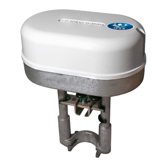
MVE2xx-65
IP65 Globe Valves Actuators
FORCE
MODEL
[N]
MVE204-65
400
MVE206-65
600
230 V AC ±
MVE210-65
1000
MVE215-65
1500
MVE222-65
2200
MVE204S-65
400
MVE206S-65
600
230 V AC ±
MVE210S-65
1000
MVE215S-65
1500
MVE222S-65
2200
APPLICATION AND USE
MVE2xx-65 is a flexible electro-mechanical actuator for the control of two and three way globe valves in:
•
heating and cooling systems
•
Air Handling Units
•
district heating plants
•
industrial temperature control systems.
MVE2xx-65 can be controlled either by a proportional (modulating)signal or by an increase/decrease (Floating) signal.
It is easy to mount and connect the actuator. Direct mounting is possible to any CONTROLLI flanged valve. Linkage kits are available
for iSMA CONTROLLI threaded valves as well as for valves of other manufacturers (table page 3).
The actuator has a fine resolution (500 steps on the full stroke range) for exacting fluid control and it is able to self-calibrate on a
different stroke without the need of any user action (this function is DIP switch selectable on the field).
MVE2xx-65 has intelligent behaviour and alarm functionality in case of unexpected operation, feedback of alarms to the user is pro-
vided by LEDs (GREEN and RED) on the control board.
N.B.: Do not use the actuator if not coupled with its relating valve.
MVE2xx-65 is suitable for harsh environment requiring IP65 protection degree.
TECHNICAL CHARACTERISTICS
DESCRIPTION
Supply voltage F N
Power consumption (running)
Power consumption (holding)
Modulating
Running
time
Increase/decrease
Stroke
Force
Duty cycle
Analogue input Y M
Digital inputs Y1 Y2
The performances stated in this sheet can be modifi ed without any prior notice.
POWER
DESCRIPTION
SUPPLY
Long yoke, modulating/
10%
floating control, IP65
Short yoke, modula-
ting/
10%
floating control, IP65
MVE204-65
MVE204S-65
10VA / 4,5W
8VA / 4W
15 s (for valves with stroke from 5 to 15 mm)
20 s (for valves with stroke from 15 to 25 mm)
30 s (for valves with stroke from 25 to 60 mm)
400 N
voltage 0-10V - impedance > 100kΩ (range: 0-10Vdc, 2-10Vdc, 0-5/2-6Vdc, 5-10/6-10Vdc)
www.ismacontrolli.com
MVE206-65
MVE210-65
MVE206S-65
MVE210S-65
230Vac ±10%, 50-60Hz
13VA / 6W
18VA / 8W
11VA / 5W
11VA / 5W
60 s
5-60 mm (limited to 30 mm for MVE2xxS-65)
600 N
1000 N
max 50%/60 minutes
500 Ω (range 4-20mA)
connection of Y1, Y2 to M
DBL561en | 1
MVE215-65
MVE222-65
MVE215S-65
MVE222S-65
21VA / 11W
25VA / 10W
13VA / 7W
10VA / 4W
(for valves with
stroke from 5 to
1500 N
Issue rev. c | 03/2022
st
60 s
60 mm)
2200 N
pag. 1
Advertisement
Table of Contents

Subscribe to Our Youtube Channel
Related Manuals for iSMA MVE2 Series


Summary of Contents for iSMA MVE2 Series
- Page 1 It is easy to mount and connect the actuator. Direct mounting is possible to any CONTROLLI flanged valve. Linkage kits are available for iSMA CONTROLLI threaded valves as well as for valves of other manufacturers (table page 3). The actuator has a fine resolution (500 steps on the full stroke range) for exacting fluid control and it is able to self-calibrate on a different stroke without the need of any user action (this function is DIP switch selectable on the field).
-
Page 2: Operation
MVE204-65 MVE206-65 MVE210-65 MVE215-65 MVE222-65 DESCRIPTION MVE204S-65 MVE206S-65 MVE210S-65 MVE215S-65 MVE222S-65 Output V+ voltage 16Vdc ± 0,5V, max load 25mA, Output U voltage 2-10Vdc (0-100%), max load 2mA Room temperature operation -10T55°C; storage -20T55°C Room humidity max 90% R.H. Protection degree IP65 Insulation class Emission/Immunity EMC 2014/30/UE according to EN 61326-1:2013 standard... - Page 3 DMVE CLOSING RELAY OPENING RELAY K2 KC1 K3 K4 KC2 Diagnostic The actuator is provided with a self diagnostic algorithm able to detect faulty conditions: • stroke calibration out of range 5-60mm; • unexpected stall condition (e.g. valve stuck or extra stroke due to actuator link loose); •...
-
Page 4: Maintenance
Current iSMA CONTROLLI valves ● (except for 2-3TGB.F PN16) VSXT09PBP, VSXT10PBP only with MVE204S-65 2-3TGB.F PN16 ● iSMA CONTROLLI valves with threaded M40 connections (except for VSB-VMB, with AG51 VSB.F-VMB.F PN16) VSB-VMB, VSB.F-VMB.F PN16 with AG52 with AG63 OTHER MANUFATURERS VALVES... -
Page 5: Terminal Block
TERMINAL BLOCK M Y1 Y2 230~V ±10% Floting only sink (connect Y1, Y2 to M) (*) In order to use the floating control the only possible connection is * Floting only sink (connect Y1, Y2 to M) between terminal M and Y1/ Y2. -
Page 6: Wiring Diagrams
WIRING DIAGRAMS 3 point floating control Modulating control (0-10 Vcc) Modulating Control (0-10Vcc) 3-point Floating Control 230Vac 230Vac Controller Controller Open Y1 F Close Command + Command - Neutral Neutral DIP SWITCHES SETTINGS Set the DIP switches according to tables below. Power down and power up again the actuator or act on the manual override handle to be sure that settings will be recognized. - Page 7 DIAGNOSTIC - ALARM FUNCTIONS ACTUATOR BEHAVIOUR TYPICAL LEDS ACTUATOR TROUBLE RESET N° ERROR AUTOMATIC CALIBRA- BEHAVIOUR SHOOTING PROCEDURE MANUAL CALIBRATION TION (DIP N. 7 ON) CONDITION (DIP N. 7 OFF) The actuator pushes/ pulls 2 times (unexpected The actuator pushes/pulls stall) trying to remove the 2 times against endpoint possible obstacle.
-
Page 8: Dimensions (Mm)
Manual control ON, the actuators ignores the control signal. RED GREEN ON ATTENTION! The electronic board is electrically supplied DIMENSIONS [mm] iSMA CONTROLLI S.p.A. - Via Garibaldi 1, 20057 Assago (MI) - Italy | support@ismacontrolli.com www.ismacontrolli.com DBL561en | 1 Issue rev. c | 03/2022...
Need help?
Do you have a question about the MVE2 Series and is the answer not in the manual?
Questions and answers