iSMA -B-MAC36NL User Manual
Hide thumbs
Also See for iSMA-B-MAC36NL:
- User manual (51 pages) ,
- Installation and startup manual (50 pages) ,
- User manual (24 pages)

Related Manuals for iSMA iSMA-B-MAC36NL


Summary of Contents for iSMA iSMA-B-MAC36NL
- Page 1 User Manual Install and Start-up Global Control 5 Sp. z o.o. Warsaw, Poland www.gc5.pl...
-
Page 2: Table Of Contents
Table of contents 1 Introduction..........................3 1.1 Revision history ........................ 3 1.2 Safety rules ........................3 1.3 Overview ..........................4 1.4 Key Features: ........................4 1.5 Technical specification ....................6 1.6 Software license notice ....................7 1.7 Dimensions ........................8 2 Hardware Specification ...................... -
Page 3: Introduction
1 Introduction 1.1 Revision history Date Description 01.10.2018 First edition Table 1 - Revision history 1.2 Safety rules • Note: Incorrect wiring of this product can cause its damage and may result in other hazards. Make sure the product has been correctly wired before turning the power ON. -
Page 4: Overview
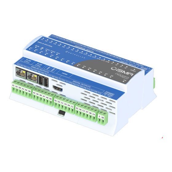
1.3 Overview The iSMA-B-MAC36NL is a compact Master Application Controller with built-in different types of I/O and operating in Niagara Framework environment. Using the specific local I/O set 16x UI, 8x AO, 4x DI and 8x DO allows to use the device in different applications. The Controller provides control, data logging, alarming, scheduling, integration and visualisation. - Page 5 Figure 1 – iSMA-B-MAC36NL Key Features Version 1.0 www.gc5.pl Page 5 / 40...
-
Page 6: Technical Specification
1.5 Technical specification Voltage 24 V AC/DC ± 20% isolated Power Supply Power consumption 14 W @ 24 V DC; 24 VA @ 24 V AC Temperature input Measurement with attached RTDs • Accuracy ±0,1˚C • For sensor Pt1000 and Ni1000 use 16-bit •... -
Page 7: Software License Notice
Baud rate From 2400 to 115,200 Address 1 to 247 2x Fast Ethernet independent mode Ethernet Baud rate 10/100 Mb/s 2x USB 1x OTG, 1x Host 1x HDMI Standard type A HDMI 1x microSD 2 GB system reserved / 2 GB user storage... -
Page 8: Dimensions
1.7 Dimensions Figure 2 – iSMA-B-MAC36NL Dimensions [mm] Version 1.0 www.gc5.pl Page 8 / 40... -
Page 9: Hardware Specification
2 Hardware Specification 2.1 Terminals and Internal Connection Diagram The iSMA-B-MAC36NL controller can be supplied by 24 V AC/DC. The power supply block is separated. The grounding pin located next to power supply terminals must be connected to the ground. -
Page 10: Power Supply Connection
2.2 Power Supply Connection The device is designed to work with 24 V AC/DC separated power supply. Figure 4 24 V AC/DC power supply connection Version 1.0 www.gc5.pl Page 10 / 40... -
Page 11: Earth Grounding
2.2.1 Earth Grounding Earth grounding provides protection from electrostatic discharge or other forms of EMI. The way to connect the controller’s ground spade lug to a nearby earth ground is shown in the figure below. 2.3 Communication Bus Connection (RS485) The device is equipped with opto-isolated RS485 base port, which allows to connect the device to the BMS in order to communicate with other devices in the network. -
Page 12: Rs485 Network Termination And Biasing
In the case of an RS485 twisted pair cable the termination is typically 120 Ω. In the iSMA-B-MAC36NL version there is a built-in 3 position Switch on the back side of the device (access after removing the back cover) which is dedicated to connect termination resistor and/or biasing resistors. - Page 13 When the switch is in the END position it connects the termination resistor 120 Ω and biasing resistors 680 Ω (pull-down to ground SG and pull-up to +5VDC) to the RS485 bus. So instead of using additional resistors, the termination and biasing can be easily done by simple switch activation.
- Page 14 When the switch is in the BIA position it connects the biasing resistors 680 Ω (pull-down to ground SG and pull-up to +5VDC) to the RS485 bus. The biasing is added to the RS485 bus in order to reduce communication failures.
-
Page 15: Led Indicators
2.4 LED Indicators The device is equipped with LEDs for quick status checking and diagnostics: Figure 10 LEDs on the front panel of iSMA-B-MAC36NL. • The Power LED ON lights up (green) and then turns the power supply on. • The Communication LED COM1 lights up (orange) for 20 ms in the transmit state for sending each package through the main RS485 port. -
Page 16: Mini Usb
The mini USB port is dedicated to debugging connection through the console. You can find a description of how to connect to the system console in Connection to the console chapter. Figure 11 LEDs on the front panel of iSMA-B-MAC36NL. Version 1.0 www.gc5.pl Page 16 / 40... -
Page 17: Local I/O
2.6 Local I/O The iSMA-B-MAC36NL has built-in different types of I/O. The specific local I/O set 16x UI, 8x AO, 4x DI and 8x DO allows to use the device in different applications. 2.6.1 Universal Inputs (16x UI) All the Universal Inputs have 16-bit ADC, which supports the following types of the input signals: •... - Page 18 2.6.1.2 Current Input connection (0 – 20 mA) Current measurement is realized by voltage measurement and 200 Ω resistance. According to the Ohm’s law the current is directly proportional to the voltage and the resistance is the constant of proportionality.
- Page 19 2.6.1.3 Temperature Input connection Temperature measurement is based on resistance. The Universal Inputs working as Temperature Inputs support the following types of sensors: 10K3A1, 10K4A1, Carel 10K, 20K6A1, 2.2K3A1, 3K3A1, 30K6A1, SIE1, TAC1, SAT1, Pt1000, Ni1000. Figure 14 Connection of UI to measure temperature 2.6.1.4 Dry Contact Input connection (Digital Input)
-
Page 20: Digital Inputs (4X Di)
2.6.2 Digital Inputs (4x DI) In addition to the standard Dry Contact Input the Digital Inputs can operate as fast pulse counters with up to 100 Hz impulse frequency counting. The Input is active when it is connected to the ground (G0). -
Page 21: Analog Outputs (8X Ao)
2.6.3 Analog Outputs (8x AO) All the Analog Outputs have 12-bit ADC, provide 10 mV resolution and accuracy less than ±0,5%. They support the following types of the output signals: • Voltage Output (0 – 10 V DC) with max. load up to 20 mA •... - Page 22 2.6.3.3 Relay to Analog Output connection There is an option to control the 12 V DC relay from the Analog Outputs (max. load cannot exceed 20 mA!). Figure 19 Relay connection to the Analog Output. Version 1.0 www.gc5.pl Page 22 / 40...
-
Page 23: Digital Outputs (8X Do)
2.6.4 Digital Outputs (8x DO) Relay Outputs (NO) have max. resistive load up to 3 A @ 30 V DC and up to 3 A @ 230 V AC.. 2.6.4.1 Resistive Load connection Figure 20 Connection of the resistive load to the Digital Output. -
Page 24: Start-Up
SD card from one unit to another (microSD Card is not assigned with the particular hardware iSMA-B-MAC36NL unit). For example, you might want to remove the SD card from a unit that suffered a hardware failure and use it in a replacement unit. - Page 25 All power to the controller needs to be shut down before inserting/removing the microSD card, otherwise equipment damage may occur. The controller needs to be unmounted from any DIN rail or screw tab mounting, as accessing the card uses space behind the mounting base.
-
Page 26: Factory Settings
3.3 Factory settings Out of the box the SD Card Image has the factory settings. Every time when the controller is restored via clean or update distribution file, the default settings are restored. Please refer to Controller System Update chapter for more details. -
Page 27: First Login To The Controller Platform In Workplace
3.4 First login to the controller platform in Workplace After opening the Workplace Software to log into the controller for the first time please do the following steps: From the menu bar, click File > Open > Open Platform. - Page 28 If the Change Platform Defaults Wizard displays, click Next to step through creating a system passphrase, creating a new platform account, and removing the default platform account, as shown below. Version 1.0 www.gc5.pl Page 28 / 40...
- Page 29 Click Finish to complete these changes. The system completes making the connection between the host and Workbench, and displays the Nav Container View. Version 1.0 www.gc5.pl Page 29 / 40...
-
Page 30: Tcp/Ip Configuration
3.5 TCP/IP Configuration TCP/IP Configuration is one of several platform views. Typically, you use it to initially configure a remote controller’s TCP/IP settings. Configuring TCP/IP communication settings is a task for the systems integrator while initially setting up a controller. - Page 31 As shown above, each Interface has the following properties at the top: A read-only OS identifier for the hardware interface, such as “eth0” for a iSMA-B-MAC36NL controller, or, for a Windows platform, either a 128-bit GUID (globally unique identifier) or a Windows network connection name, such as “Local Area Connection 2”.
- Page 32 To review, click the expand control to see all entries. For the iSMA-B-MAC36NL controller, you can edit its host file. To add an entry, click at the end of the last line and press Enter.
- Page 33 If connected to the iSMA-B-MAC36NL controller, the DNS and gateway settings are also “host- level” parameters in the TCP/IP Configuration view, as shown below. * For a Windows-based host, DNS and gateway settings are available under each Interface section.
- Page 34 To save yourself some time when making multiple changes, enter all changes before you continue. When you finish the configuration, click Save. The system displays: Reboot the controller for the changes to take effect. Version 1.0 www.gc5.pl Page 34 / 40...
-
Page 35: Connection To The Console
3.6 Connection to the console If a more complex troubleshooting, analysis or changes of the iSMA-B-MAC36NL controller are required, console mode could be used. Console mode is often used to connect to the controller with unknown Network Settings. To put the controller into the debug system console mode, plug-in the USB-to-MiniUSB cable. -
Page 36: Controller System Update
After downloading the update from the GC5's support website, the zip file should be unpacked. You will receive two files - the first is a configuration file (file nre-config-iSMA-iSMA-B- MAC36NL.dist), the second file containing the appropriate updated system component. Both files should be copied to the directory C:\Users\(User folder)\Niagara4.4\vykon\sw\inbox. - Page 37 Installing the update After logging into the Platform of the controller, click the right mouse button on the Platform and run the Commissioning Wizard process Passing through the next wizard windows, an additional window will appear informing you about the need to update the appropriate controller system component (OS, NEL, JVM).
- Page 38 Current version numbers of the controller’s system component can be checked in the Platform / Platform Administration. Version 1.0 www.gc5.pl Page 38 / 40...
-
Page 39: Restore Controller To The Default State
3.8 Restore controller to the default state At times it may be necessary to restore an controller to a known good empty state, either to recommission it with the current release build, or before recommissioning it with an earlier build. - Page 40 After that you must re-install the software versions to the controller, open a version of Workbench that uses the same software version (N4.4) that you want on the controller, and use the Platform \ Commissioning Wizard to install the desired software build.
Need help?
Do you have a question about the iSMA-B-MAC36NL and is the answer not in the manual?
Questions and answers