iSMA -B-AAC20 User Manual
Hide thumbs
Also See for iSMA-B-AAC20:
- User manual (16 pages) ,
- User manual (55 pages) ,
- User manual (7 pages)

Related Manuals for iSMA iSMA-B-AAC20


Summary of Contents for iSMA iSMA-B-AAC20
- Page 1 User Manual Platform AAC20 Global Control 5 Sp. z o.o. Warsaw, Poland www.gc5.pl...
-
Page 2: Table Of Contents
AAC20 Table of contents 1 Revision history ........................4 2 Sedona Updater ........................4 2.1 IP connection ....................... 5 2.2 RS485 connection ....................... 5 2.3 Sending file to the device ................... 6 2.4 Restoring the device’s default settings ..............6 2.5 System Console ...................... - Page 3 AAC20 11 SOX protocol ........................... 43 12 Local IO ............................ 44 12.1 Adding Local IO components .................. 45 12.2 Local IO Config ......................46 13 One Wire ..........................48 13.1 Adding OneWire network ..................48 13.2 Discovering OneWire sensors ................. 49 13.3 Adding sensors manually ..................
-
Page 4: Revision History
05.02.2018 2 Sedona Updater Sedona Updater is a piece of software designed to administer an operating system of iSMA- B-AAC20 controller. The software is free and can be obtained from your distribution partner or download from GC5 support website: www.support.gc5.pl. The software allows the following actions (using the buttons in the lower part of the window): Send File –... -
Page 5: Ip Connection
In order to operate using the RS485 port connection, you must run “Bootloader” mode on the device. Bootloader in version with built-in display (iSMA-B-AAC20-LCD): Step 1 - Disconnect the power and wait for the device to fully shut down, Step 2 - Hold the Esc button down, and turn the power on again. The screen should now display “Bootloader”. -
Page 6: Sending File To The Device
AAC20 Step 2 - With the device off, take the cover off and move the DIP Switch no 8 to ON position, turn the power on again. Activation of the Bootloader mode is confirmed by alternating power and communication LEDs. - Page 7 AAC20 Management” section and press “Refresh Log” button. All system logs will be displayed on the window bellow. Figure 2 AAC20 Web page Device Manager USB connection system console To view the logs,use SedonaUpdater.exe software and connect device using the A-A USB cable.
-
Page 8: Firmware Upgrade
AAC20 Figure 3 Sedona updater console view This connection method is recommended when user cannot connect using IP or RS485 ports or don’t know connection parameters for example IP address. 2.6 Firmware upgrade Firmware can be updated by uploading the device with an appropriate firmware file, and reloaded with new firmware. -
Page 9: Checking Firmware Version
AAC20 Step 3a - Send files by IP connection – Using IP connection controller will automatically run Bootloader mode. Open SedonaUpdater.exe and set up communication parameters : Tab Modbus TCP, IP Address – Controller IP address (default for new devices 192.168.1.123), Modbus TCP/IP port –... - Page 10 AAC20 By Workplace To verify the current firmware version, log in to the device and go to the Plat component. The Plat component is located in the Service folder, directly below the App component (Sedona -> App -> Service -> plat). Plat contains the "Firmware Version" slot identifying the working firmware version.
-
Page 11: Sedona In Workplace
AAC20 3 Sedona in WorkPlace Sedona device configuration and programming is based on the WorkPlace software. Out of the box, WorkPlace has no plugin to handle Sedona devices and it should be installed. The installation files can be downloaded from the "Niagara Central" website or obtained from your distribution partner. -
Page 12: Importing Kits To Workplace
AAC20 Figure 5 Sedona Framework installer second window Step 3 – Upon successful installation of Sedona environment, restart WorkPlace by clicking the “Restart Workbench” option followed by the Finish button. Figure 6 Sedona Framework installer last window 3.2 Importing kits to Workplace To import files to WorkPlace it is recommended to use “Sedona Installer”... - Page 13 AAC20 Singly – by choosing single kit file with .kit extension Figure 7 Sedona environment files installer single file Open Sedona installer from Tools menu in Workplace, mark “Install Sedona environment files” option and select kit file. Press next button to finish importing process. This process copies this file to Sedona kits folder.
-
Page 14: Installing Ismaui Module
AAC20 Groups – by choosing prepared bundle file with zip extension Figure 8 Sedona environment files installer software bundle Open Sedona installer from Tools menu in Workplace, mark “Install Sedona environment files” option and select zip file. Press next button to finish importing process. This process copies all kit files from zip archives to Sedona kits folder. - Page 15 AAC20 Figure 9 Sedona Device connection window By default, a new device should have the following values: IP address – 192.168.1.123, Port – 1876, User – admin, Password – empty box (no characters). The connection parameters can be changed after connect to controller: IP address –...
-
Page 16: Sedona Tools
AAC20 4 Sedona Tools Sedona Tools is a part of the WorkPlace tools dedicated to manage device applications and kits. In this view we can also see device installed kits with kits checksum (to recognize kits version). More information about Sedona Tools can be found in docSedonaSoxTools.pdf under Niagara docs files, installed in your machine in the Niagara installation process. - Page 17 AAC20 Kit Manager, you can add and remove kits, as well as change versions of kits deployed in the scode running on the device. Also, you have the option to force the kits.scode to be rebuilt. The kits.scode must be rebuilt whenever a change affects the schema. This ensures such changes are included in the recompiled binary .scode image.
-
Page 18: Backup/Restore Tool
"clean" device. There are three backup options available: Sedona VM Backup - backup of the Sedona Virtual Machine (not supported by iSMA-B- AAC20) app.sab and kits.scode Backup - backup of application files app.sab and kits.scode (kits image). -
Page 19: Application Manager
AAC20 4.4 Application Manager The App Manager tool is used to manage app.sax file. The app.sax is Sedona Application XML file which is a simple XML representation of a Sedona Framework app that is easily generated and consumed by Sedona Framework software tools. This file can be opened and changed in offline mode. -
Page 20: Licence
AAC20 5 Licence Sedona controllers have built-in licence mechanism. All out of box controllers have installed standard licence version and it is ready to work. But in case of licence changing or after memory clear the licence must be re-uploaded. There are two modes of doing it:: Online mode, Offline mode. -
Page 21: Sedona Licence - Offline Mode
Licence file can be download using ismaUI to local database, copy from other PC or sent by email from local iSMA distributor. Open SedonaUpdater.exe software and choose licence file (proper file format is “MAC address (without dots)”.dat). After success upload reboot controller using “Reboot Device”... - Page 22 AAC20 Figure 16 Sedona application structure view Device Name – Device Name text, App Name – Application Name text, Scan Period – One cycle execution time, Scan Time – Real time of one cycle execution, Guard Time – Reserve time to finish system tasks, Time To Steady State - Time from app start to steady state, Hibernation Resets Steady State –...
-
Page 23: Plat Service
AAC20 6.1 Plat service The Plat service is the component, which shows device mains parameters, licence status and allows to manage IP address. This component is placed under the Service folder and is associated with device hardware. The component has the following actions: Restart –... - Page 24 AAC20 Figure 17 Plat component view The component has following slots: Status – Platform status, Platform ID – Platform ID, Platform Ver – Platform Version, Mem Available – Controller RAM memory available, State – Licence status, Cpu Usage – CPU usage from last 5 seconds, Serial Number –...
-
Page 25: Change Ip Address
AAC20 Obtain DNS Server Address Automatically – when DHCP is true, this option allow to get DNS IP address automatically form DHPC or manually, DNS Server 1 – First DNS server IP address, DNS Server 2 – Second DNS server IP address, Device Password –... -
Page 26: Users Service
AAC20 Changing the IP address using the display (only devices with built-in display) To change the IP address from the display, hold the F1 function key down until the screen shows "Enter password". Then input a numeric password (slot "Device password", plat component, the default is 1000). - Page 27 AAC20 Users can have the following types of rights: Operator Read – Read components, read values of operator properties, Operator Write – Change values of operator properties, Operator Invoke – Invoke operator actions, Admin Read – Read values of properties, read links, generate components links, Admin Write –...
-
Page 28: Date Service
AAC20 Provisioning Permissions: Can provision app – can read/write app.sab file, Can provision app – can read/write kits.scode file, Can provision app – can read/write SVM files. For devices with built-in LCD, displaying components such as action editing/invoking is defined by assigning the given component to a group and defining access rights for user from this group. -
Page 29: Nv Components
NVBooleanWritable is the component that stores the output value in non-volatile memory of EEPROM device. After rebooting the device or the power failure, the component value is restored from this particular memory. iSMA-B-AAC20 has 1536 Boolean memory cells. The occupied space meter for EEPROM is embedded in the plat component. NVBooleanWritable Version 1.3... - Page 30 AAC20 component occupies two Boolean memory cells (value of the component, and position of the Auto / Hand switch). The NVBooleanWritable has the following actions: Set - this option sets User slot and In slot if there is no link on In slot...
-
Page 31: Nvintegerwritable
EEPROM device. After rebooting the device or power failure, the component value is restored from this particular memory. iSMA-B-AAC20 has 1536 Boolean memory cells and 512 numeric cells. Space meter of the occupied EEPROM's memory is located in the plat component. -
Page 32: Nvnumericwritable
EEPROM device. After rebooting the device or power failure, the component value is restored from this particular memory. iSMA-B-AAC20 has 1536 Boolean memory cells and 512 numeric cells. Space meter of the occupied EEPROM's memory is located in the plat component. - Page 33 AAC20 NVBooleanWritable has the following actions: Set – this option sets User slot and In slot if there is no link on In slot , Set In Hand – this option sets value on Out slot and block changing from any other slots, Set In Auto –...
- Page 34 AAC20 The component has the following slots: Status – Point actual status Auto / Hand, Alarm – Alarm extension, History – History extension type, Totalize – Totalize extension, Out – Output slot, In – Input Slot, User – User value slot (setting by Set action), Default –...
-
Page 35: Historical
AAC20 8 Historical iSMA-B-AAC20 device has an embedded historical extension for writing trends in microSD card memory. By default, the device is not equipped with an SD card, Historical Service SD card should be installed when necessary. The historical extension can be added only in NVBooleanWirtable, NVIntegerWritable and NVNumericWritable components. -
Page 36: History Extensions - Interval
AAC20 8.2 History extensions – Interval Interval history extension is used to collect data at specified time intervals. When you choose interval option in NV component, a history interval will be created under the history and link to NV point Out slot will be created. For configuration and settings, please refer to historical components under the history service. -
Page 37: History Extensions - Cov
AAC20 8.3 History extensions – COV COV history extension is used to collect data whenever required changes has been made. When you chose COV option in NV component, a history COV component will be created under the history service and a link with NV point Out slot will be made. For configuration settings please refer to historical components under the history service. -
Page 38: History Extensions - Cov_Interval
AAC20 8.4 History extensions – COV_Interval COV_Interval history extension is used to collect data whenever required changes has been made or at specified time intervals (whatever happens first). When you chose COV_Interval option in NV component, a history COVInterval component is created under the history service and a link with NV point Out slot will be made. -
Page 39: Alarms
AAC20 9 Alarms The device has a service that allows recording events / alarms. Alarms can be generated off the NV-type components only. Alarms can be recorded only on the SD card. By default, the device is not equipped with an SD card, to use Alarm Service, SD card should be installed. -
Page 40: Alarm Boolean Points
AAC20 9.2 Alarm Boolean points The Boolean alarm extension can be added only in NVBooleanWritable components. To add the extension, choose “Change Of State” in Alarm slot and an alarm extension will be created automatically under NV component. Figure 28 Alarm boolean extension property sheet view Alarm extension slots: Alarm Inhibit –... -
Page 41: Alarm Numeric Points
AAC20 9.3 Alarm Numeric points The Numeric alarm extension can be added only in NVNumericWritable components. To add the extension, choose “Out Of Range” in Alarm slot, and the alarm extension will be created automatically. Figure 29 Alarm numeric extension property sheet view The component has the following slots: Alarm Inhibit –... -
Page 42: Scheduler
AAC20 High Limit – High limit alarm generation value, Low Limit – low limit alarm generation value, Deadband – High and low limit dead band value High Limit Text – Description in alarm high state, Low Limit Text – Description in alarm low state, To Normal Text - Description in normal state. -
Page 43: Sox Protocol
AAC20 11 SOX protocol Sox is the standard protocol used to communicate with Sedona devices. To serve Sox protocol Sox is also used by WorkPlace to program controller. Note that Sox is service type and it is execute after application components. So if there is a little deference between scan period and Scan Time (see App component) the services don’t have time execute and the programming... -
Page 44: Local Io
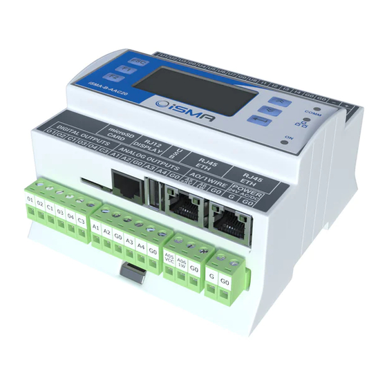
AAC20 12 Local IO The iSMA-B-AAC20 device has 22 built-in physical inputs and outputs: 8x Universal Inputs All Universal Inputs have 16-bit resolution which support the following types of inputs: Temperature Input support the following types of sensors:10K3A1, 10K4A1, Carel 10K, 20K6A1, 2.2K3A1, 3K3A1, 30K6A1, SIE1, TAC1, SAT1, Pt1000, Ni1000, accuracy ±... -
Page 45: Adding Local Io Components
AAC20 12.1 Adding Local IO components Local IO’s are supported by the components of the iSMA_LocalIO Kit. The components of this kit should be placed in a special folder localIO. Note: It is recommended to pass the signal inputs and outputs through NV components. -
Page 46: Local Io Config
AAC20 AODigital - Component for servicing Universal Output in the digital mode (false - 0V, true - 10V) LocalIOConfig - Component for configuration of physical input/output parameters of the device. 12.2 Local IO Config Figure 33 Local IO config property sheet view Version 1.3... - Page 47 AAC20 LocalCOnfig is the component designed to configure the physical input/output of the device. It consists of the following slots: UIx Type - The type of temperature sensor connected to Universal Input; table stored in the device allows you to convert the value of sensor resistance into temperature. Available...
-
Page 48: One Wire
DS18D20 chip. OneWire bus use 3 wire cable (+5 VCC, Data, GND) max 100m long (it is recommended to use shorter distance) and up to 32 sensors. All iSMA-B-AAC20 devices are equipment with OneWire port which use two Analog Outputs AO5 and AO6. -
Page 49: Discovering Onewire Sensors
AAC20 13.2 Discovering OneWire sensors OneWire network has Discover action (under right mouse button). This action will automatically searched and detect all sensors connected to the bus. It will also create Discover folder and place all found sensors there. All sensors have unique address assigned by manufacturer (slot Address).
Need help?
Do you have a question about the iSMA-B-AAC20 and is the answer not in the manual?
Questions and answers