iSMA -B-MAC36NL User Manual
Local io
Hide thumbs
Also See for iSMA-B-MAC36NL:
- User manual (51 pages) ,
- Installation and startup manual (50 pages) ,
- User manual (24 pages)

Subscribe to Our Youtube Channel
Related Manuals for iSMA iSMA-B-MAC36NL


Summary of Contents for iSMA iSMA-B-MAC36NL
- Page 1 User Manual Local IO Global Control 5 S.A. Warsaw, Poland www.gc5.pl...
-
Page 2: Table Of Contents
2.6 Digital Outputs (8x DO) ....................9 2.6.1 Resistive Load Connection..................9 2.6.2 Solenoid Valve Connection ..................9 3 Local IO Driver ........................10 3.1 iSMA IO Network ......................10 3.2 Local IO Device ....................... 11 3.3 Universal Input ........................ 13 3.4 Digital Input ........................17 3.5 Digital Input Counter ...................... -
Page 3: Introduction
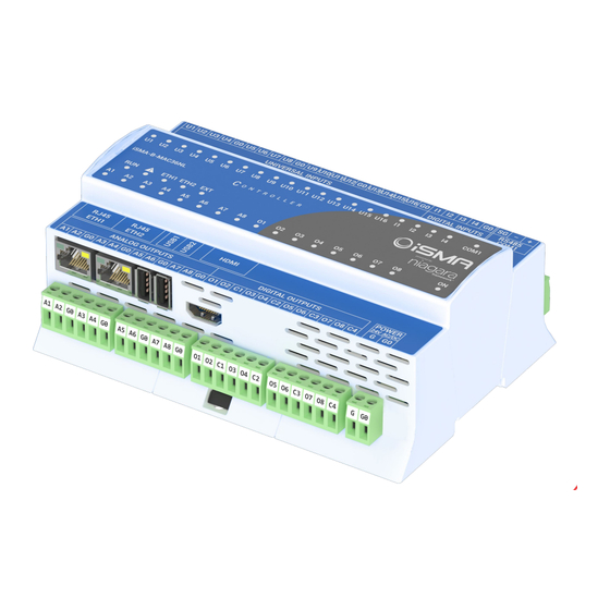
Rotary and DIP switches support added Table 1. Revision history 1.2 Overview The iSMA-B-MAC36NL is a compact Master Application Controller with built-in different types of I/O and operating in the Niagara Framework environment. Figure 1. iSMA-B-MAC36NL Key Features Version 1.2 www.gc5.pl... -
Page 4: Local Io Hardware Specification
Local IO Manual 2 Local IO Hardware Specification The iSMA-B-MAC36NL has built-in different types of I/O. The specific local I/O set 16x UI, 8x AO, 4xDI and 8x DO allows using the device in different applications. 2.1 Terminals and Internal Connection Diagram The iSMA-B-MAC36NL controller can be supplied by 24 V AC/DC. -
Page 5: Led Indicators
2.2 LED Indicators The device is equipped with LEDs for quick status checking and diagnostics: Figure 3. LEDs on the front panel of iSMA-B-MAC36NL. 1. The Universal Inputs LEDs U1-U16 indicate the statuses of the Universal Inputs. When the LED is ON, the resistance value connected to the input is lower than the switching threshold value (Dry Contact input is active). -
Page 6: Voltage Input Connection (0 - 10 V Dc)
Local IO Manual 2.3.1 Voltage Input Connection (0 – 10 V DC) Figure 4. Connection of UI to measure voltage 0-10 V DC. 2.3.2 Current Input Connection (0 – 20 mA) Current measurement is realized by voltage measurement and 200 Ω resistance. -
Page 7: Temperature Input Connection
Local IO Manual 2.3.3 Temperature Input Connection Temperature measurement based on resistance. The Universal Inputs working as Temperature Inputs support the following types of sensors: series NTC 10K3A1, 10K4A1, Carel 10K, 20K6A1, 2.2K3A1, 3K3A1, 30K6A1, SIE1, TAC1, SAT1 and Pt1000, Ni1000. -
Page 8: Digital Inputs (4X Di)
Local IO Manual 2.4 Digital Inputs (4x DI) In addition to the standard Dry Contact Input, Universal Inputs can operate as fast pulse counters with up to 100 Hz impulse frequency counting. The Input is active when it is connected to the ground (G0). -
Page 9: Relay To Analog Output Connection
Local IO Manual 2.5.2 Relay to Analog Output Connection There is an option to control the 12 V DC relay from the Analog Outputs (max. load cannot exceed 20 mA!). Figure 10. Relay connection to the Analog Output. 2.6 Digital Outputs (8x DO) Relay Outputs (NO) have max. -
Page 10: Local Io Driver
• Digital Output 3.1 iSMA IO Network The iSMA IO Network component is a network component for the Local IO Device such as the iSMA-B-MAC36NL devices (added using Local IO Device component). The iSMA IO Network component is the only right parent component for Local IO Device components. All the iSMA- B-MAC36NL devices with the points inside iSMA IO Network do not consume any of the license points. -
Page 11: Local Io Device
Bad Parent – iSMA IO Network component has been placed in the wrong place (Drivers only) Duplicated Component – iSMA IO Network component has been placed twice Invalid Hardware – iSMA IO Driver has been used on a device other than iSMA-B-MAC36NL device 3. Enabled – enable/disable iSMA IO Network component Figure 14. - Page 12 Local IO Manual Fault – there is a fault described in the Fault Cause slot. 2. Fault Cause - describes the cause of the fault if a fault or down occurs None – no fault Bad Parent - component inserted in the wrong place in the structure (the only correct place...
-
Page 13: Universal Input
Local IO Manual 3.3 Universal Input Universal Input component is used for supporting physical local Universal Inputs. Figure 17. Universal Input Component The component must be placed under LocalIODevice component. The component can be configured to work in all modes of the Universal Input (resistance, temperature, voltage, current and digital). - Page 14 Local IO Manual following slots: 2.1. Status - the current status of the component. Ok - the component is working correctly. Disabled – the component or its parent (device or network) is disabled (“Enable” slot is set to “false”) Fault- there is a fault described in the Fault Cause slot.
- Page 15 Local IO Manual Figure 19. Universal Input: Input Type List • Voltage – The Universal Input works as a voltage input: 0 - 10 VDC. Resistance measurement is disabled. • Current - The universal input works as a current input: 0 - 20 mA. Resistance measurement is disabled.
- Page 16 Local IO Manual Temperature sensor type TAC1 (ºC) Temperature sensor type SAT1 (ºC) Temperature sensor type PT1000 (16-bit resolution pre-set by the manufacturer) (ºC) Temperature sensor type NI1000 (16-bit resolution pre-set by the manufacturer) (ºC) Temperature sensor type NI1000 LG (ºC) Temperature sensor type NI1000 21C (ºC)
-
Page 17: Digital Input
Local IO Manual repeatedly without having to re-enter it. The UI component can also be copied between stations, both online and offline (PC copy). You can also copy the Custom Table slot itself and paste it into a new UI component under ProxyExt (where there is no Custom Table yet). There can only be one Custom Table slot in the UI component. - Page 18 Local IO Manual Figure 22. Digital Input Component AX Property Sheet View The Digital Input component has the following slots: Facets - determines how the input value will be displayed. Proxy Ext - component handles the point configuration and has the following slots: Status - the current status of the component.
- Page 19 Local IO Manual Enabled - Enable/disable the component Poll Frequency - Selection of the poll frequency of the points, the available options: Fast, Normal, Slow. Input Number - Selecting an input number, if a point is added to a device, the component selects the first unused input number automatically Max Input Number –...
-
Page 20: Digital Input Counter
Local IO Manual 3.5 Digital Input Counter Digital Input Counter component is designed for reading high-speed counter of Digital Inputs. Figure 23. Digital Input Counter Component The component must be placed under Local IO Device component. Figure 24. Digital Input Counter Component AX Property Sheet View The Digital Input Counter component has the following slots: Facets - determines how the input value will be displayed. - Page 21 Local IO Manual Bad Parent - component inserted in the incorrect place in the structure (the only correct place is the Device component or a subfolder of the Device component). Duplicated Component - when a component with a given address already exists (prevents double representation of input/output within a given application) Invalid Type - a type of component not supported by the device.
-
Page 22: Analog Output
Local IO Manual 3.6 Analog Output Analog Output component is designed for supporting physical local Analog Outputs working as voltage output (range 0 V – 10 V) or PWM. Figure 25. Analog Output Component The component must be placed under Local IO Device component. - Page 23 Local IO Manual Analog Output component has the following slots: Facets - determines how the input value will be displayed. Proxy Ext - component handles the point configuration and has the following slots: Status - the current status of the component.
- Page 24 Local IO Manual PWM10Hz - The Analog Output operates in PWM mode with a frequency of 10 Hz PWM100Hz - The Analog Output operates in PWM mode with a frequency of 100 Hz PWM01Hz - The Analog Output operates in PWM mode with a frequency of 0,1 Hz PWM001Hz - The Analog Output operates in PWM mode with a frequency of 0,01 Hz Figure 27.
-
Page 25: Digital Output
Local IO Manual Emergency Override - overwrites the value of the component with the highest priority (In1), this action does not expire automatically in order to disable it, enable the Emergency Auto action. Emergency Auto – restores the component to automatic operation; disables Emergency Override actions. - Page 26 Local IO Manual Figure 29. Digital Output Component AX Property Sheet View The Digital Output component has the following slots: Facets - determines how the input value will be displayed. Proxy Ext - component handles the point configuration and has the following slots: Status - the current status of the component.
- Page 27 Local IO Manual Disabled - component or parent (device or network) is disabled (the "Enable" slot is set to "false") Fault- there is a fault described in the Fault Cause slot. Down – no response from the point. Fault Cause - describes the cause of the fault in case of a fault or down status.
- Page 28 Local IO Manual short cycling of equipment controlled by the point. Min Inactive Time - timer to specify the minimum inactive time. Typical usage is to prevent short cycling of equipment controlled by the point. Set Min Inactive Time on Start - If the slot value is set to true, the Min Inactive Time timer is enabled from the start of the station.
-
Page 29: Rotary Switch
Figure 30. Rotary Switch Component The component must be placed under the Local IO Device component. Components Rotary Switch S1 and S2 are not visible on the Isma Point Manager view (if ISMA_IO.wb is installed). Figure 31. Rotary Switch Component AX Property Sheet View The Rotary Switch component has the following slots: 1. - Page 30 Local IO Manual Down – no response from the point; 2.2. Fault Cause – describes the cause of a fault or down status: None – no fault, Bad Parent – the component is incorrectly placed in the structure (the only correct place is the Device component or a subfolder of the Device component), Disabled –...
-
Page 31: Dip Switch
Figure 33. Dip Switch Component The component must be placed under the Local IO Device component. Components Dip Switch S3 and S4 are not visible on the Isma Point Manager view (if ISMA_IO.wb is installed). Figure 34. Dip Switch Component AX Property Sheet View Version 1.2... - Page 32 Local IO Manual The DIP Switch component has the following slots: 1. Facets – determines how the output value will be displayed. 2. Proxy Ext – component’s extension that handles its configuration with the following slots: 2.1. Status – the current status of the component: Ok –...
- Page 33 Local IO Manual on the selected DIP switch S3/S4. The ProxyExt component’s extension has the following actions: Force Write Config – instantly saves the component’s existing configuration to the device; Force Read – sends a query immediately, despite the settings in Poll Frequency.
Need help?
Do you have a question about the iSMA-B-MAC36NL and is the answer not in the manual?
Questions and answers