
Related Manuals for iSMA SMA-B-LP


Summary of Contents for iSMA SMA-B-LP
- Page 1 User Manual Modbus Global Control 5 Sp. z o.o. Warsaw, Poland www.gc5.pl...
-
Page 2: Table Of Contents
Table of contents Introduction ................................... 5 Revision history ..................................5 Safety rules ....................................5 Technical specifications ................................6 Room Panel versions ................................7 ........................................8 Dimensions ....................................8 Power supply and Communication ..........................9 DC power connection ................................10 AC power connection ................................10 Connecting the communication bus (RS485) ........................ - Page 3 Room Panel/Modbus Room Panel Modes ................................21 LCD Display ....................................22 4.8.1 Icons displaying..................................... 22 4.8.1.1 LCD_ICON_DISPLAY (40219) ..................................23 4.8.1.2 LCD_ICON_FLASHING (40220) ................................. 23 4.8.1.3 LCD_ICON_FLASHING_TIME (40221) ..............................24 4.8.1.4 SUBMENU_ICON_FLASHING (40229) ..............................24 4.8.1.5 SUBMENUICON_FLASHING_TIME (40222) .............................. 25 4.8.2...
- Page 4 Room Panel/Modbus 6.12.1 Operating Mode is “true” (see Operating Mode) ..........................38 6.12.2 Operating Mode is false (see Operating Mode ) ..........................39 Fan Configuration Registers ............................ 40 FAN_CURRENT_SPEED (41601) ............................40 FAN_MODE (41602) ................................40 FAN_TYPE (41603) ................................. 41 FAN_MODE_NAME (41604-41612).............................
- Page 5 Room Panel/Modbus 11.1.7.14 % Unit Active bit 14 ....................................58 11.1.7.15 h Unit Active bit 15 ....................................58 11.2 Boolean parameter type registers ............................58 11.2.1 XPresentValue (X = [1.8]) ..................................58 11.2.2 XName (X = [1.8]) ....................................58 11.2.3...
-
Page 6: Introduction
• Added description of Submenu Boolean All present Value registers Added information about BACnet MS/TP protocol 06.06.2017 Added new version of the Panel (iSMA-B-LP(-XX)-1) 16.11.2017 Table 1 Revision history Safety rules Note: Incorrect wiring of this product can damage the product and lead to other hazards. -
Page 7: Technical Specifications
Room Panel/Modbus Technical specifications Voltage 24V AC/DC ± 20% Power consumption iSMA-B-LP(-1) 0.5 W (24 V DC), 0.75 VA (24 VAC) iSMA-B-LP-H(-1) 0.5 W (24 V DC), 0.75 VA Power supply (24 VAC) iSMA-B-LP-C(-1) 0.7 W (24 V DC), 1 VA (24 V AC) iSMA-B-LP-HC(-1) 0.7 W (24 V DC), 1 VA... -
Page 8: Room Panel Versions
Table 3 Room Panel Sensor Configuration versions *There are two versions of keypad icons set available: standard and optional. The ordering code for a standard keypad icons set panel version is iSMA-B-LP(-XX), and for the optional icons set is iSMA-B-LP(-XX)-1. -
Page 9: Dimensions
Room Panel/Modbus Dimensions Figure 1 Room Panel iSMA-B-LP dimensions version 1.3 www.gc5.pl Page 8 / 121... -
Page 10: Power Supply And Communication
Room Panel/Modbus Power supply and Communication The Room Panel iSMA-B-LP can be powered with 24 V AC/DC. Power consumption depends on power supply voltage type used and CO sensor presence (see Technical specification table). There are two RJ12 sockets mounted on the back side of the Room Panel (Figure 2). -
Page 11: Dc Power Connection
Room Panel/Modbus DC power connection Figure 4 DC power supply connection AC power connection Figure 5 AC power supply connection Connecting the communication bus (RS485) Figure 6 RS485 connection version 1.3 www.gc5.pl Page 10 / 121... -
Page 12: Connecting More Room Panels In The Network
Room Panel/Modbus Connecting more Room Panels in the network It is possible to connect more Room Panels into the one network in a very simple way. Additional RJ12 socket can be used to connect another Room Panel by using one single cable. -
Page 13: Connection By Usb
Room Panel/Modbus Connection by USB USB connection is dedicated for maintenance and settings. USB port (mini type B) is located at the bottom of the device (Figure 9). Figure 9 Mini-USB port USB connection provides Power Supply for the Room Panel (+5 V DC) so there is no need for additional power supply in this connection type. -
Page 14: Restoring The Default Settings
Room Panel/Modbus Restoring the default settings To restore the default configuration of all registers, follow the below steps: Turn power supply OFF Set switch no. 1 on the DIP-switch to ON position. Figure 11 Switch no. 1 position for default setting restore procedure Turn power supply ON, LCD display starts blinking. -
Page 15: Main Parameters
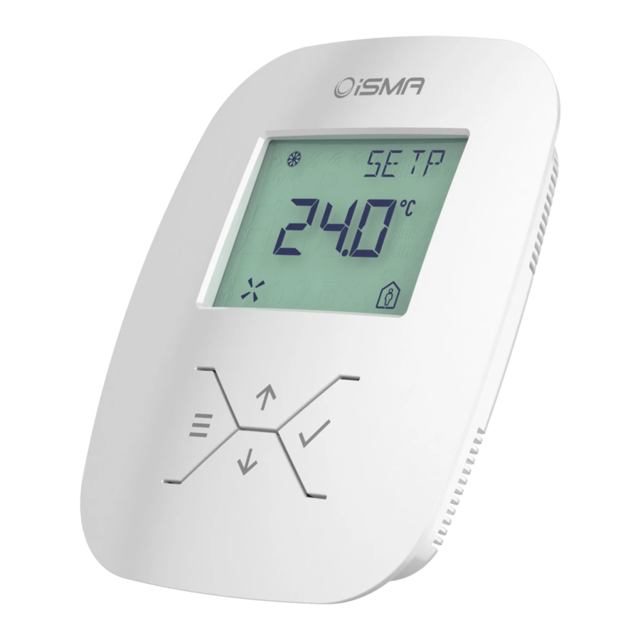
Room Panel/Modbus Main parameters iSMA-B-LP is a wall panel with 2.3” LCD display and four function buttons. Additionally, the panel has the in-built temperature sensor and optionally the humidity and CO sensors. iSMA-B-LP is powered with 24 V AC/DC and has the in-built RS485 port (Modbus RTU/ASCII) and BACnet MS/TP. -
Page 16: Communication Parameters
Room Panel/Modbus Communication parameters 4.3.1 COUNTER_OF_RECEIVED_MESSAGES (30004) 32-bit register with the number of valid Modbus messages received by the Room Panel from the time of the last power-up. The value is reset after power cycle or after changing of transmission parameters (speed, stop bits, parity, etc.). -
Page 17: Parity_Bit (40020)
Room Panel/Modbus 4.3.6 PARITY_BIT (40020) Each byte of data being transferred may have additional protection as a parity bit added before stop bit (bits). The method of calculating parity bit determines the below table: Register value Type of parity bit... -
Page 18: Time Configuration
Room Panel/Modbus Time configuration The time (if activated) is displayed on the 14-segment display block. After restart of the device clock is not displayed. It starts to be visible after the Room Panel receives first message with correct time value. -
Page 19: Device Configuration
Room Panel/Modbus 4.4.6 EXIT_MENU_TIME (40225) The register contains the time value after which Submenu Edit mode and Settings Submenu Edit mode is finished and the device leads the user back to the Main Menu displaying. Time starts after the last Key Pad activation (pushing any button). This register has min. -
Page 20: Device Configuration Register (40205)
Room Panel/Modbus 4.5.4 DEVICE_ACTIONS (40001) Setting register 40001 according to the table below enables 1 of 4 available actions: reset device, reload settings, reset settings or enter bootloader. Register Register value Action value decimal hexadecimal 0x01FF Reset 0x02FF Reload settings... -
Page 21: Co2_In_Alarm_Flashing_Lcd (Register 40205, Bit 5)
Room Panel/Modbus 4.6.5 CO2_IN_ALARM_FLASHING_LCD (Register 40205, bit 5) Bit 5 of register 40205 switch on function LCD background illumination flashing when CO2 alarm occur. When bit 5 is “true” CO2 Alarm is indicated by LCD display flashing. Read more about CO2 Alarm in CO2 sensor. By default bit is “false”... -
Page 22: Lcd_Flashing (Register 40205, Bit 13)
Room Panel/Modbus The Main Menu is displayed. By default bit is “false” (Key Pad ON). 4.6.11 LCD_FLASHING (Register 40205, bit 13) Bit 13 of register 40205 is responsible for LCD display flashing activation. When the bit 13 is „true”, LCD display flashes with the frequency stored in LCDIconFlashing register. -
Page 23: Lcd Display
LCD Display The Room Panel iSMA-B-LP is equipped with 2.3” LCD display with backlight. By default LCD display is turned ON (when the device is powered) and basic parameters from in-built sensors together with user defined parameters are shown in the Main Menu. -
Page 24: Lcd_Icon_Display (40219)
Room Panel/Modbus for Icon Indication. 4.8.1.1 LCD_ICON_DISPLAY (40219) Each bit of the register is responsible for displaying a particular icon. Setting true value for single bit displays appropriate icon which is assigned to that bit according to Table no. 12 below. By default, all icons are hidden (all bits of the register are “false”). -
Page 25: Lcd_Icon_Flashing_Time (40221)
Room Panel/Modbus 4.8.1.3 LCD_ICON_FLASHING_TIME (40221) It is possible to set Icon blinking frequency. Register LCD_ICON_FLASHING_TIME stores the time which constitutes the base for calculating Icon blinking frequency. This register has min. value of 50 ms. Default value is 500 ms (the icons are visible fo 500 ms and hidden for 500/4=125 ms). -
Page 26: Submenuicon_Flashing_Time (40222)
Room Panel/Modbus 4.8.1.5 SUBMENUICON_FLASHING_TIME (40222) The Submenu Icons light up according to the status of assigned process. These icons are not editable, however the user can choose if each submenu icon is to be visible or not. Register SUBMENU_ICON_FLASHING_TIME stores the time which constitutes the base for calculating a frequency of submenu icons’... -
Page 27: 4.8.3 Lcd_Background_Illumination_Settings
Room Panel/Modbus If one or more user defined parameters have the same priority, register with the lowest address is displayed first. In the upper right corner of the display there are four 14-segment displays dedicated for the clock, submenu and parameters’ names. These names are stored in the special Submenu registers as a ASCII code values corresponding to the following characters (from the left side) of the submenu name. -
Page 28: Key Pad
Panel stays in other modes than “Active” and it is powered). When the beeper is active, single pushing of any button emits the beeper sound. Figure 15 Left: Standard Key Pad view iSMA-B-LP(-XX), Right: Optional Key Pad view iSMA-B-LP(-XX)-1 4.9.1 Menu button When the device is in Active mode, single pushing of the button opens the Fan Menu. -
Page 29: 4.9.4 Key Pad Background Illumination Settings
Room Panel/Modbus 4.9.4 Key Pad Background Illumination Settings When one of four keypad buttons is pressed, the Room Panel changes state into Active mode. The same situation happens when the power supply is reconnected or after the Room Panel restart. In case when there is no keypad activity and the Room Panel stays ON, the subsequent Background illumination modes activate. -
Page 30: Sensors Configuration
Room Panel/Modbus Sensors Configuration There are 3 different sensors which can be built-in in the Room Panel (depending on which Room Panel version is chosen - see Table • Temperature sensor • Humidity sensor • CO sensor Actual values from all in-built sensors can be displayed in the Main Menu in a specific order (see section Display). -
Page 31: Temperature_Sensor_Offset (40304)
Room Panel/Modbus 5.1.2 TEMPERATURE_SENSOR_OFFSET (40304) The register contains a value which allows for setting correction for temperature sensor’s actual value indication. The offset value can be positive or negative. The register value is also multiplied by 10 as in case of Temperature sensor actual value register. The actual temperature offset value is added to temperature sensor indication. -
Page 32: Temperature_Configuration (40316, Bit 0 And Bit 4)
Room Panel/Modbus 5.1.5 TEMPERATURE_CONFIGURATION (40316, bit 0 and bit 4) Name Active Not active Active(def) ThirdPointActive No decimal Decimal(def) Table 14 Temperature Configuration Bit 0 of register 40316 is responsible for activation or deactivation of the visibility of temperature sensor. If bit 0 is active temperature sensor actual value is visible in Main Menu. -
Page 33: Humidity_Configuration(Register 40317, Bit 0 And Bit 4)
Room Panel/Modbus displayed as a text (name) on 14 segment display block, together with the HUMIDITY_SENSOR_ACTUAL_VALUE register (displayed on 8-segment display block). In case when a particular character value is 0 (NULL), the character is not displayed. Lower case characters are automatically changed into upper case characters. The default value is 1296648277 which corresponds to the name “HUMI”. -
Page 34: Co 2 _Filter (40309)
Room Panel/Modbus 5.3.3 CO _FILTER (40309) Register contains time constant for CO sensor low pass filter, in seconds. The value is expressed in seconds. The default filter value is 60 seconds. Setting value 0 disables the filter. 5.3.4 CO... -
Page 35: Setpoint Registers
Room Panel/Modbus Figure 17 CO2 Alarm functioning with CO2 differential for Alarm active Setpoint registers SETPOINT_VALUE (41501) The register stores actual Setpoint value multiplied by 10. After device restart, the value is read from Default Setpoint Value register and set as actual setpoint value. Default value is 210. -
Page 36: Setpoint_Low_Limit (41505)
Room Panel/Modbus SETPOINT_LOW_LIMIT (41505) Minimal setpoint value which can be set by user, multiplied by 10. The default value is 180 SETPOINT_HIGH_LIMIT (41506) Maximal setpoint value which can be set by user, multiplied by 10. The default value is 240 OFFSET_RANGE (41507) Register contains a value which limits OffsetSetpoint value change multiplied by 10. -
Page 37: Setpoint_Name (41511)
Room Panel/Modbus register (displayed on 8-segment display block). In case when particular character value is 0 (NULL), the character is not displayed. Lower case characters are automatically changed into upper case characters. The default value is 1179864902 which corresponds to the name “OFFS”. -
Page 38: Third_Point_Active (Register 41513, Bit 4)
Room Panel/Modbus Figure 18 Setpoint changing view: A) Setpoint without decimal B) Offset without decimal C) Setpoint with decimal D) Offset with decimal 6.11.5 THIRD_POINT_ACTIVE (Register 41513, bit 4) Bit 4 true value activates setpoint display precision to the first decimal place. If bit 4 is “false”, setpoint is displayed as integer value (without decimal place). -
Page 39: 6.12 Setting Setpoint
Room Panel/Modbus Setpoint Normal Edit mode When the bit 5 is “false”, Normal Edit mode is active. Setpoint can be changed by the arrow buttons. The newly chosen Setpoint has to be confirmed by pushing the OK button. Confirmation of entering the new Setpoint is signalized by double blink of the new Setpoint and double beeper signal (if enabled, DEVICE_CONFIGURATION bit 0). -
Page 40: Operating Mode Is False (See Operating Mode )
Room Panel/Modbus 6.12.2 Operating Mode is false (see Operating Mode ) In case, when Operating Mode is “false”, the user changes Setpoint indirectly by changing Offset. When SETPOINT_CONFIGURATION bit 3 Setpoint Display is “false” then OffsetSetpoint is displayed. When Offset is in Edit Mode, its value, unit and name flash with frequency calculated according to the value stored in SUBMENU_ICON_FLASHING_TIME register. -
Page 41: Fan Configuration Registers
Room Panel/Modbus Fan Configuration Registers The Room Panel allows Fan control with actual Fan status indication. There are special group of icons responsible for fan status indication. Fan Configuration registers allow to select different fan control modes corresponding to different fan types. According to actual fan status different icons combinations are displayed. -
Page 42: Fan_Type (41603)
Room Panel/Modbus Panel is in Active Mode. Particular fan modes availability depends on FAN_TYPE register value (see table 17). Default texts for particular fan modes can be changed (see Fan Mode Name). This register has software limitation where the max. value is 4. -
Page 43: Fan_Mode_Name (41604-41612)
Room Panel/Modbus WARNING!: The register values from 4 to 6 (1-3 Speed Fan without AUTO mode) have to be set when fan works in Local Mode (see FanLocalMode). 7.4 FAN MODE NAME (41604-41612) For user-friendly use, FAN_MODE register value is displayed on LCD as a text instead of numeric value. -
Page 44: Fan_Config_Fast_Edit_Mode (Register 41614, Bit 5)
Room Panel/Modbus Fan Full Edition In Fan Full Edition mode all modes stored in FAN_MODE register are available from Fan Edit Submenu level. Fan Part Edition In Fan Part Edition mode user can switch only between Auto and OFF FAN_MODE from Fan Edit Submenu level, all other fan modes are unavailable. -
Page 45: Fan_Config_Local_Mode (Register 41614, Bit 6)
Room Panel/Modbus 7.5.5 FAN_CONFIG_LOCAL_MODE (Register 41614, Bit 6) Local Mode If the bit 6 is “true” the Room Panel fan setting works in a local mode. It means that the value of the FAN_CURRENT_SPEED register is determined by the value of the FAN_MODE register and so the value of the FAN_CURRENT_SPEED register cannot be overwritten by the higher level system. -
Page 46: Occupancy Registers
Room Panel/Modbus Occupancy Registers Occupancy mode setting is available from Main Menu level. When Room Panel is in Active Mode, single pushing of the OK button leads the user to Occupancy Edit Submenu. On 14- segment display block text “OCCM”... -
Page 47: Occupancy_Mode_Name (41703-41705)
Room Panel/Modbus 8.3 OCCUPANCY_MODE_NAME (41703-41705) For a more user-friendly use, OCCUPANCY_MODE register value is displayed on LCD as a text instead of numeric value. There are two 32-bit registers assigned with two different occupancy modes, which can contain up to 4 characters according to the ASCII code (see... -
Page 48: Occupied_Config_Local_Mode (Register 41707, Bit 6)
Room Panel/Modbus Occupancy Normal Edit mode When the bit 5 is “false” Normal Edit mode is active. Particular occupancy modes are selected by arrow buttons. The newly chosen Occupancy mode has to be confirmed by pushing the OK button. - Page 49 Room Panel/Modbus Occupancy Mode Occupancy Current Status Visualization Register value Register value Table 25 Overwriting OCCUPANCY CURRENT SPEED register by OCCUPANCY MODE register in Local mode BMS Mode If bit 6 is “false”, the Room Panel occupancy setting works in BMS mode.
-
Page 50: Registers Adjustable Locally From The Room Panel
Room Panel/Modbus Registers adjustable locally from the Room Panel Access from the Main Menu level to any settings menu is possible when the Room Panel is in Active Mode. OK button together with Menu button have to be pushed longer than the time value stored in ENTER_MENU_TIME register. -
Page 51: Device (Dev)
Room Panel/Modbus 9.2 Device (DEV) Device settings menu contains registers responsible for global settings. Change of any of particular parameter has influence on different modes and functions implemented in the Room Panel. Some of the parameters refer to time settings such as Time format Enter Menu time, Exit Menu Time or Refresh Time. -
Page 52: Temperature (Temp)
Room Panel/Modbus 9.3 Temperature (TEMP) Temperature Settings menu contains registers referring to temperature sensor display and temperature control settings. User is able to switch on/off temperature sensor value display, set temperature sensor filter or change temperature sensor offset. All available parameters... -
Page 53: Co2 (Co2)
Room Panel/Modbus 9.5 CO2 (CO2) Settings menu contains registers referring to CO sensor display and CO control settings. User is able to switch on/off CO sensor value display, set CO sensor filter or change CO sensor offset. All available parameters are presented in the table below:... -
Page 54: Setpoint (Setp)
Room Panel/Modbus 9.6 Setpoint (SETP) In the Setpoint Settings menu user has access to main setpoint registers. It is possible to change locally from the Room Panel most useful Setpoint parameters, such as default setpoint, low and high setpoint limit, setpoint STEP or offset range. User can also decide if Setpoint value should be displayed in the Main Menu or if Setpoint or offset should be changed during Setpoint Edition. -
Page 55: Fan (Fan)
Room Panel/Modbus Fan (Fan) The registers of the Fan Settings Menu refer to Fan Configuration settings. User can change fan type or decide if Fan Status should be displayed in the Main Menu or not. Parameter Editable can determine if user can change particular Fan Modes. All available parameters are... -
Page 56: Main Menu User Defined Parameters
Room Panel/Modbus Main Menu user defined parameters. There are 8 numeric and 8 Boolean user-defined parameters available in the Main Menu. All of them are Read Only type locally for the Room Panel (Read & Write type for the higher level system) and they are written to EEPROM memory (register values are remembered after the room Panel restart or power failure). -
Page 57: Xpresentvalue (X = [1.8])
Room Panel/Modbus 11.1.1 XPresentValue (X = [1.8]) The register contains actual value of the parameter. The default value is 0. 11.1.2 XName (X = [1.8]) There is one 32-bit register which can contain up to 4 characters (ASCII code) which can be displayed as a text (name) on 14-segment display block together with the Present Value register (displayed on 8-segment display block). -
Page 58: Editable Bit 1
Room Panel/Modbus 11.1.7.2 Editable bit 1 Bit 1 activates edition of the parameter value locally from the Room Panel. When the bit is “true” parameter is editable and user can change its value. By default the bit is “false” (not editable). -
Page 59: M3H Unit Active Bit 11
Room Panel/Modbus 11.1.7.11 m3h Unit Active bit 11 If the bit is “true”, then together with actual parameter Present Value the m3h unit is displayed. The default value is 0. 11.1.7.12 %Rh Unit Active bit 12 If the bit is “true”, then together with actual parameter Present Value the %Rh unit is displayed. -
Page 60: Xtruetext (X = [1.8])
Room Panel/Modbus 11.2.3 XTrueText (X = [1.8]) To user-friendly use, Present Value register value is displayed on LCD as a text instead of numeric value. There is one 32-bit register assigned with Active state of the Present Value register, which can contain up to 4 characters according to the ASCII code (see example in Temperature Name). -
Page 61: 11.3 Submenu Menuactivepoints Registers
Room Panel/Modbus 11.3 Submenu MenuActivePoints registers For each Submenu there is a special register which indicates if there is any active parameters inside the particular submenu. If the value of Menu Active Points register is higher than 0, it means that there is at least one active parameter in Submenu and icon assigned to that submenu is displayed. -
Page 62: List Of All Modbus Registers
Room Panel/Modbus List of all Modbus Registers The table below shows all registers available for the Room Panel. Modbus Register Name Access Description Address Address Address First byte means version and another one type of a 40001 0x00 VERSION_TYPE Read &... - Page 63 Room Panel/Modbus Modbus Register Name Access Description Address Address Address KEY_PAD_CURRENT_VALUE 40203 0xCA HOURS Read & Write Hours part in time display 40204 0xCB MINUTES Read & Write Minutes part in time display Name Beeper Not active Active(def) Format...
- Page 64 Room Panel/Modbus Modbus Register Name Access Description Address Address Address PAD_TIME_TO_IDLE Memory BACKGROUND_ILLUMINATION Read & Write 40216 0xD7 Default 5 sec KEY_PAD_TIME_TO_STANDBY Memory Read & Write 40217 0xD8 REFRESH_TIME Default 2 sec Memory Read & Write Bit 0 = 1 clock is visible (default)
- Page 65 Room Panel/Modbus Modbus Register Name Access Description Address Address Address that time. Default time: 500ms. Time which is the base for calculating frequency of Icon flashing. Icons are visible for 100% of the time Read & Write 40222 0xDD...
- Page 66 Room Panel/Modbus Modbus Register Name Access Description Address Address Address Read & Write Name 40316 0x13B TEMPERATURE_CONFIGURATION Memory Active Not active Active(def) ThirdPointActive No decimal Decimal(def) Read & Write Name 40317 0x13C HUMIDITY_CONFIGURATION Memory Active Not active Active(def) ThirdPointActive...
- Page 67 Room Panel/Modbus Modbus Register Name Access Description Address Address Address Name Visible Not visible Visible(def) Editable Not Editable Editable(def) Opperating Changing Changing Read & Write Mode Offset Setpoint(def) 41513 1512 0x5E8 SETPOINT_CONFIGURATION Memory 3 Setpoint Display Show/change Show/change Offset...
- Page 68 Room Panel/Modbus Modbus Register Name Access Description Address Address Address auto mode Register Fan type Comment value 0-10V(def) Fan is controlled by Read & Write 41603 1602 0x642 FAN_TYPE analog value 0-10 VDC Memory 1- Speed 1-Speed Fan 2- Speed...
-
Page 69: 12.1.1 List Of User Defined Parameters Modbus Registers
Room Panel/Modbus Modbus Register Name Access Description Address Address Address NAME (32–bits) Memory OCCUPANCY_MODE_1 Read & Write 41705 1704 0x6A8 Name for OCCUPANCY MODE = 1. Default = OCC NAME (32–bits) Memory Name Visible Not visible Visible(def) Read &... - Page 70 Room Panel/Modbus Modbus Register Name Access Description Address Address Address % unit active not_visible(def) visible h unit active not_visible(def) visible Read & MAIN_MENU_NUMERIC2 40052 0x33 Write Present value of the parameter PRESENTVALUE Memory Read & MAIN_MENU_NUMERIC2 Displaying user-defined parameter name.
- Page 71 Room Panel/Modbus Modbus Register Name Access Description Address Address Address Memory Read & MAIN_MENU_NUMERIC5 table 40343 0x156 Write CONFIGURATION MAIN_MENU_NUMERIC1Configuration(30323) Memory Read & MAIN_MENU_NUMERIC6 40056 0x37 Write Present value of the parameter PRESENTVALUE Memory Read & MAIN_MENU_NUMERIC6 Displaying user-defined parameter name.
- Page 72 Room Panel/Modbus Modbus Register Name Access Description Address Address Address 7 Boolean8PresentValue Not active(def) Active Read & MAIN_MENU_BOOLEAN1 40114 0x71 Write Present value of the parameter PRESENTVALUE Memory Read & MAIN_MENU_BOOLEAN1 Displaying user-defined parameter name. 40360 0x167 Write NAME (32–bits) Memory Read &...
- Page 73 Room Panel/Modbus Modbus Register Name Access Description Address Address Address Memory Read & MAIN_MENU_BOOLEAN3 Text for parameter “false” state value. 40382 0x17D Write FALSETEXT (32–bits) Memory Read & MAIN_MENU_BOOLEAN3 Priority of the parameter for sequence of display in 40384...
- Page 74 Room Panel/Modbus Modbus Register Name Access Description Address Address Address Read & MAIN_MENU_BOOLEAN6 40119 0x76 Write Present value of the parameter PRESENTVALUE Memory Read & MAIN_MENU_BOOLEAN6 Displaying user-defined parameter name. 40405 0x194 Write NAME (32–bits) Memory Read & MAIN_MENU_BOOLEAN6 Text for parameter “true”...
-
Page 75: 12.1.3 Temperature Submenu
Room Panel/Modbus Modbus Register Name Access Description Address Address Address FALSETEXT (32–bits) Write Memory Read & MAIN_MENU_BOOLEAN8 Priority of the parameter for sequence of display in 40429 0x1AC Write PRIORITY Main Menu Memory Read & Name MAIN_MENU_BOOLEAN8 Write 40440... - Page 76 Room Panel/Modbus Modbus Register Name Access Description Address Address Address Name Active Not active(def) Active(def) FirstPointActive Decimal(def) decimal(def) SecondPointActive Not Decimal(def) decimal(def) ThirdPointActive Decimal(def) decimal(def) C unit active not_visible(def) visible Read & TEMPERATURE_NUMERIC1 F unit active not_visible(def) visible 40510...
- Page 77 Room Panel/Modbus Modbus Register Name Access Description Address Address Address Read & TEMPERATURE_NUMERIC3 Displaying user-defined parameter name. 40522 0x209 Write NAME (32–bits) Default name: Num2 Memory Read & TEMPERATURE_NUMERIC3 STEP during parameter value changing. 40524 0x20B Write STEP The default value is 0 Memory Read &...
- Page 78 Room Panel/Modbus Modbus Register Name Access Description Address Address Address Read & TEMPERATURE_NUMERIC5 Minimal value of the parameter. 40543 0x21E Write LOW_LIMIT The default value is 0 Memory Read & TEMPERATURE_NUMERIC5 Maximal value of the parameter. 40544 0x21F Write...
- Page 79 Room Panel/Modbus Modbus Register Name Access Description Address Address Address Read & TEMPERATURE_NUMERIC7 Priority of the parameter for sequence of display in 40563 0x232 Write PRIORITY Submenu Memory Read & TEMPERATURE_NUMERIC7 See the table in 40564 0x233 Write CONFIGURATION...
- Page 80 Room Panel/Modbus Modbus Register Name Access Description Address Address Address Active Not active(def) Active Editable Not editable Editable(def) Read & TEMPERATURE_BOOLEAN2 40123 0x7A Write Present value of the parameter PRESENT_VALUE Memory Read & TEMPERATURE_BOOLEAN2 Displaying user-defined parameter name. 40586...
- Page 81 Room Panel/Modbus Modbus Register Name Access Description Address Address Address Memory Read & TEMPERATURE_BOOLEAN4 Text for parameter “true” state value. 40608 0x25F Write TRUETEXT (32–bits) Memory Read & TEMPERATURE_BOOLEAN4 Text for parameter “false” state value. 40570 0x261 Write FALSETEXT (32–bits) Memory Read &...
- Page 82 Room Panel/Modbus Modbus Register Name Access Description Address Address Address PRIORITY Write Submenu Memory Name Read & TEMPERATURE_BOOLEAN6 40633 0x278 Write Active Not active(def) Active CONFIGURATION Memory Editable Not editable Editable(def) Read & TEMPERATURE_BOOLEAN7 40127 0x7F Write Present value of the parameter...
-
Page 83: 12.1.4 Fan Submenu
Room Panel/Modbus 12.1.4 Fan Submenu Modbus Register Name Access Description Address Address Address Read & FANNUMERIC1 40067 0x42 Write Present value of the parameter PRESENT_VALUE Memory Read & 40654 0x28D FANMENUACTIVEPOINTS Write Number of active parameters in submenu Memory Read &... - Page 84 Room Panel/Modbus Modbus Register Name Access Description Address Address Address PRESENT_VALUE Write Memory Read & FANNUMERIC2 Displaying user-defined parameter name. 40666 0x299 Write NAME (32–bits) Default name: Num2 Memory Read & FANNUMERIC2 STEP during parameter value changing. 40668 0x301...
- Page 85 Room Panel/Modbus Modbus Register Name Access Description Address Address Address Read & FANNUMERIC4 STEP during parameter value changing. 40686 0x2AD Write STEP The default value is 0 Memory Read & FANNUMERIC4 Minimal value of the parameter. 40687 0x2AE Write...
- Page 86 Room Panel/Modbus Modbus Register Name Access Description Address Address Address Read & FANNUMERIC6 Maximal value of the parameter. 40706 0x2C1 Write HIGH_LIMIT The default value is 0 Memory Read & FANNUMERIC6 Priority of the parameter for sequence of display in...
- Page 87 Room Panel/Modbus Modbus Register Name Access Description Address Address Address Read & FANNUMERIC8 40726 0x2D5 Write See the table in FanNumeric1Configuration(40510) CONFIGURATION Memory Read & FAN_BOOLEAN_ALL 40109 0x6C Write See the table in 30107 register PRESENT_VALUES Memory Read &...
- Page 88 Room Panel/Modbus Modbus Register Name Access Description Address Address Address Memory Read & FANBOOLEAN3 Displaying user-defined parameter name. 40749 0x2EC Write NAME (32–bits) Memory Read & FANBOOLEAN3 Text for parameter “true” state value. 40751 0x2EE Write TRUETEXT 32 – BITS) Memory Read &...
- Page 89 Room Panel/Modbus Modbus Register Name Access Description Address Address Address FALSETEXT (32–bits) Write Memory Read & FANBOOLEAN5 Priority of the parameter for sequence of display in 40775 0x306 Write PRIORITY Submenu Memory Name Re Read FANBOOLEAN5 40776 0x307 & Write...
- Page 90 Room Panel/Modbus Modbus Register Name Access Description Address Address Address Editable Not editable Editable(def) Read & FANBOOLEAN8 40137 0x88 Write Present value of the parameter PRESENT_VALUE Memory Read & FANBOOLEAN8 Displaying user-defined parameter name. 40799 0x31E Write NAME (32–bits) Memory Read &...
-
Page 91: 12.1.5 Light Submenu
Room Panel/Modbus 12.1.5 Light Submenu Modbus Register Name Access Description Address Address Address Read & LIGHTNUMERIC1 40075 0x4A Write Present value of the parameter PRESENT_VALUE Memory Read & 40807 0x326 LIGHT_MENU_ACTIVE_POINTS Write Number of active parameters in submenu Memory Read &... - Page 92 Room Panel/Modbus Modbus Register Name Access Description Address Address Address PRESENT_VALUE Write Memory Read & LIGHTNUMERIC2 Dispalying user-defined parameter name. 40819 0x332 Write NAME (32–bits) Default name: Num2 Memory Read & LIGHTNUMERIC2 STEP during parameter value changing. 40821 0x334...
- Page 93 Room Panel/Modbus Modbus Register Name Access Description Address Address Address Read & LIGHTNUMERIC4 STEP during parameter value changing. 40839 0x346 Write STEP The default value is 0 Memory Read & LIGHTNUMERIC4 Minimal value of the parameter. 40840 0x347 Write...
- Page 94 Room Panel/Modbus Modbus Register Name Access Description Address Address Address Read & LIGHTNUMERIC6 Maximal value of the parameter. 40859 0x35A Write HIGH_LIMIT The default value is 0 Memory Read & LIGHTNUMERIC6 Priority of the parameter for sequence of display in...
- Page 95 Room Panel/Modbus Modbus Register Name Access Description Address Address Address Read & LIGHTNUMERIC8 40879 0x36E Write See the table in LightNumeric1Configuration(40510) CONFIGURATION Memory Read & LIGHTBOOLEANALL 40110 0x6D Write See the table in 30107 register PRESENT_VALUES Memory Read &...
- Page 96 Room Panel/Modbus Modbus Register Name Access Description Address Address Address Memory Read & LIGHTBOOLEAN3 Displaying userdefined parameter name. 40902 0x385 Write NAME (32–bits) Memory Read & LIGHTBOOLEAN3 Text for parameter “true” state value. 40904 0x387 Write TRUETEXT (32–bits) Memory Read &...
- Page 97 Room Panel/Modbus Modbus Register Name Access Description Address Address Address FALSETEXT (32–bits) Write Memory Read & LIGHTBOOLEAN5 Priority of the parameter for sequence of display in 40928 0x39F Write PRIORITY Submenu Memory Name Re Read LIGHTBOOLEAN5 40929 0x3A0 & Write...
- Page 98 Room Panel/Modbus Modbus Register Name Access Description Address Address Address Editable Not editable Editable(def) Read & LIGHTBOOLEAN8 40145 0x90 Write Present value of the parameter PRESENT_VALUE Memory Read & LIGHTBOOLEAN8 Displaying user-defined parameter name. 40952 0x3B7 Write NAME (32–bits) Memory Read &...
-
Page 99: 12.1.6 Blind Submenu
Room Panel/Modbus 12.1.6 Blind Submenu Modbus Register Name Access Description Address Address Address Read & BLINDNUMERIC1 40083 0x52 Write Present value of the parameter PRESENT_VALUE Memory Read & BLIND_MENU 40960 0x3BF Write Number of active parameters in submenu ACTIVE_POINTS Memory Read &... - Page 100 Room Panel/Modbus Modbus Register Name Access Description Address Address Address PRESENT_VALUE Write Memory Read & BLINDNUMERIC2 Displaying user-defined parameter name. 40972 0x3CB Write NAME (32–bits) Default name: Num2 Memory Read & BLINDNUMERIC2 STEP during parameter value changing. 40974 0x3CD...
- Page 101 Room Panel/Modbus Modbus Register Name Access Description Address Address Address Read & BLINDNUMERIC4 STEP during parameter value changing. 40992 0x3DF Write STEP The default value is 0 Memory Read & BLINDNUMERIC4 Minimal value of the parameter. 40993 0x3E0 Write...
- Page 102 Room Panel/Modbus Modbus Register Name Access Description Address Address Address Read & BLINDNUMERIC6 Maximal value of the parameter. 41012 1011 0x3F3 Write HIGH_LIMIT The default value is 0 Memory Read & BLINDNUMERIC6 Priority of the parameter for sequence of display in...
- Page 103 Room Panel/Modbus Modbus Register Name Access Description Address Address Address Read & BLINDNUMERIC8 41032 1031 0x407 Write See the table in BlindNumeric1Configuration(40510) CONFIGURATION Memory Read & BLIND_BOOLEAN_ALL 40111 0x6E Write See the table in 30107 register PRESENT_VALUES Memory Read &...
- Page 104 Room Panel/Modbus Modbus Register Name Access Description Address Address Address Memory Read & BLINDBOOLEAN3 Displaying user-defined parameter name. 41055 1054 0x41E Write NAME (32–bits) Memory Read & BLINDBOOLEAN3 Text for parameter “true” state value. 41057 1056 0x420 Write TRUETEXT (32–bits) Memory Read &...
- Page 105 Room Panel/Modbus Modbus Register Name Access Description Address Address Address FALSETEXT (32–bits) Write Memory Read & BLINDBOOLEAN5 Priority of the parameter for sequence of displaying 41081 1080 0x438 Write PRIORITY in Submenu Memory Name Re Read BLINDBOOLEAN5 41082 1081 0x439 &...
- Page 106 Room Panel/Modbus Modbus Register Name Access Description Address Address Address Editable Not editable Editable(def) Read & BLINDBOOLEAN8 40153 0x98 Write Present value of the parameter PRESENT_VALUE Memory Read & BLINDBOOLEAN8 Displaying user-defined parameter name. 41105 1104 0x450 Write NAME (32–bits) Memory Read &...
-
Page 107: 12.1.7 Alarms Submenu
Room Panel/Modbus 12.1.7 Alarms Submenu Modbus Register Name Access Description Address Address Address Read & ALARMSNUMERIC1 40091 0x5A Write Present value of the parameter PRESENT_VALUE Memory Read & 41113 1112 0x458 ALARMSMENUACTIVEPOINTS Write Number of active parameters in submenu Memory Read &... - Page 108 Room Panel/Modbus Modbus Register Name Access Description Address Address Address PRESENT_VALUE Write Memory Read & ALARMSNUMERIC2 Displaying user-defined parameter name. 41125 1124 0x464 Write NAME (32–bits) Default name: Num2 Memory Read & ALARMSNUMERIC2 STEP during parameter value changing. 41127...
- Page 109 Room Panel/Modbus Modbus Register Name Access Description Address Address Address Read & ALARMSNUMERIC4 STEP during parameter value changing. 41145 1144 0x478 Write STEP The default value is 0 Memory Read & ALARMSNUMERIC4 Minimal value of the parameter. 41146 1145...
- Page 110 Room Panel/Modbus Modbus Register Name Access Description Address Address Address Read & ALARMSNUMERIC6 Maximal value of the parameter. 41165 1164 0x48C Write HIGH_LIMIT The default value is 0 Memory Read & ALARMSNUMERIC6 Priority of the parameter for sequence of displaying...
- Page 111 Room Panel/Modbus Modbus Register Name Access Description Address Address Address Read & ALARMSNUMERIC8 See the table in 41185 1184 0x4A0 Write CONFIGURATION AlarmsNumeric1Configuration(40510) Memory Read & 40112 0x6F ALARMS_ALL_PRESENT_VALUES Write See the table in 30107 register Memory Read &...
- Page 112 Room Panel/Modbus Modbus Register Name Access Description Address Address Address Memory Read & ALARMSBOOLEAN3 Displaying user-defined parameter name. 41208 1207 0x4B7 Write NAME (32–bits) Memory Read & ALARMSBOOLEAN3 Text for parameter “true” state value. 41210 1209 0x4B9 Write TRUETEXT (32–bits) Memory Read &...
- Page 113 Room Panel/Modbus Modbus Register Name Access Description Address Address Address FALSETEXT (32–bits) Write Memory Read & ALARMSBOOLEAN5 Priority of the parameter for sequence of displaying 41234 1233 0x4D1 Write PRIORITY in Submenu Memory Name Re Read ALARMSBOOLEAN5 41235 1234 0x4D2 &...
- Page 114 Room Panel/Modbus Modbus Register Name Access Description Address Address Address Editable Not editable Editable(def) Read & ALARMSBOOLEAN8 40161 0xA0 Write Present value of the parameter PRESENT_VALUE Memory Read & ALARMSBOOLEAN8 Displaying user-defined parameter name. 41258 1257 0x4E9 Write NAME (32–bits) Memory Read &...
-
Page 115: 12.1.8 Occupancy Submenu
Room Panel/Modbus 12.1.8 Occupancy Submenu Modbus Register Name Access Description Address Address Address Read & SETTINGSNUMERIC1 40099 0x62 Write Present value of the parameter PRESENT_VALUE Memory Read & 41266 1265 0x4F1 SETTINGS_MENU_ACTIVE_POINTS Write Number of active parameters in submenu Memory Read &... - Page 116 Room Panel/Modbus Modbus Register Name Access Description Address Address Address Read & SETTINGSNUMERIC2 40100 0x63 Write Present value of the parameter PRESENT_VALUE Memory Read & SETTINGSNUMERIC2 Displaying user-defined parameter name. 41278 1277 0x4FD Write NAME (32–bits) Default name: Num2 Memory Read &...
- Page 117 Room Panel/Modbus Modbus Register Name Access Description Address Address Address Read & SETTINGSNUMERIC4 STEP during parameter value changing. 41298 1297 0x511 Write STEP The default value is 0 Memory Read & SETTINGSNUMERIC4 Minimal value of the parameter. 41299 1298...
- Page 118 Room Panel/Modbus Modbus Register Name Access Description Address Address Address Read & SETTINGSNUMERIC6 Maximal value of the parameter. 41318 1317 0x525 Write HIGH_LIMIT The default value is 0 Memory Read & SETTINGSNUMERIC6 Priority of the parameter for sequence of displaying...
- Page 119 Room Panel/Modbus Modbus Register Name Access Description Address Address Address Read & SETTINGSNUMERIC8 See the table in 41338 1337 0x539 Write CONFIGURATION SettingsNumeric1Configuration(40510) Memory Read & OCCUPANCY_ALL 40113 0x70 Write See the table in 30107 register PRESENT_VALUES Memory Read &...
- Page 120 Room Panel/Modbus Modbus Register Name Access Description Address Address Address Memory Read & SETTINGSBOOLEAN3 Displaying user-defined parameter name. 41361 1360 0x550 Write NAME (32–bits) Memory Read & SETTINGSBOOLEAN3 Text for parameter “true” state value. 41363 1362 0x552 Write TRUETEXT (32–bits) Memory Read &...
- Page 121 Room Panel/Modbus Modbus Register Name Access Description Address Address Address FALSETEXT (32–bits) Write Memory Read & SETTINGSBOOLEAN5 Priority of the parameter for sequence of displaying 41387 1386 0x56A Write PRIORITY in Submenu Memory Name Re Read SETTINGSBOOLEAN5 41388 1387 0x56B &...
- Page 122 Room Panel/Modbus Modbus Register Name Access Description Address Address Address Editable Not editable Editable(def) Read & SETTINGSBOOLEAN8 40169 0xA8 Write Present value of the parameter PRESENT_VALUE Memory Read & SETTINGSBOOLEAN8 Displaying user-defined parameter name. 41411 1410 0x582 Write NAME (32–bits) Memory Read &...
Need help?
Do you have a question about the SMA-B-LP and is the answer not in the manual?
Questions and answers