
Related Manuals for iSMA B-FCU


Summary of Contents for iSMA B-FCU
- Page 1 User Manual Quick Start-up www.ismacontrolli.com DMP245en | 1st Issue rev. 1 | 04/2022...
-
Page 2: Table Of Contents
Step 6: Selecting Type of Control Required by the FCU Valves and Connection Details............................14 Step 7: Selecting the Temperature Control Value Source and its Connection Details............................16 3.8.1 Temperature Source: iSMA-B-LP/Touch Point Room Panel........16 3.8.2 Temperature Source Connected to S3 ................16 3.8.3 Temperature Source Connected to S1 ................17 3.8.4... - Page 3 Quick Start-up Connections Overview.......................21 Connection Examples........................21 4.2.1 4-Pipe Installation with 1 Stage Digital Controlled Heating and Cooling and Analog Controlled Fan ......................21 4.2.2 4-Pipe Installation with 1 Stage Digital Controlled Heating and Cooling and 1 Speed Fan..........................22 4.2.3...
-
Page 4: Introduction
Quick Start-up 1 Introduction This manual explains basic procedures for using the controller, setting up the built-in application and information on connection details. It is recommended to read this manual before using the controller. For detailed operating procedures and troubleshooting information, see user manuals: FCU Programming, FCU Application, FCU Hardware, FCU Updater. -
Page 5: Overview
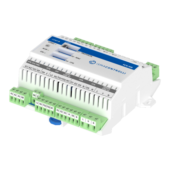
The iSMA-B-FCU controller comes in a box along with the connectors and the iSMA-B-FCU installation instruction. 2.2 Tools To safely and properly set up the iSMA-B-FCU controller, the flat head screwdriver 3.0 x 0.5 mm is necessary. 2.3 Dimensions and Mounting The controller dimensions and mounting details are presented on the figure 1. -
Page 6: Configuring And Connecting The Controller
Note: The detailed information about the DIP switches configuration is available in the FCU Hardware manual. The iSMA-B-FCU controller configuration step by step is described in chapter 3 of this document and consists of steps: Step 1: configuration of the PROTOCOL DIP switch responsible for selecting used protocol and its baud rate, and restoring the controller to the default settings;... -
Page 7: Step 1: Selecting Protocol And Baud Rate; Restoring The Default Settings
Quick Start-up Steps 3-8 describe configuration of the CFG DIP switch. Their overview with default positioning is presented in the table below. Name Default Pipe Mode 2-pipe 4-pipe 4-pipe Enable Disable Disable Heating 2 Stage Enable Disable Disable Cooling 2... -
Page 8: Restoring Default Settings
ON (1) ON (1) BACnet Slave Table 4. Protocol configuration 3.2.2 Restoring Default Settings To restore the default iSMA-B-FCU device settings, follow the steps below: • Turn off the power supply. • Set the 6 switch of the PROTOCOL DIP switch to ON. -
Page 9: Step 2: Setting Controller Address
Quick Start-up 3.3 Step 2: Setting Controller Address 3.3.1 MAC DIP Switch Configuration For the controller to operate correctly in the network, its address needs to be set to the desired value. The controller address is set by the MAC DIP switch. The state of the MAC DIP switch represents binary information of the controller address. -
Page 10: Step 3: Choosing The Fcu Pipe Type
For another address DIP switch configuration, see the iSMA-B-FCU Hardware manual. 3.4 Step 3: Choosing the FCU Pipe Type The iSMA-B-FCU can be used in 4-pipe installations as well as in 2-pipe installations. In order for the controller to operate correctly in the application, it is necessary to know the fan coil pipe type and set the CFG DIP switch to the corresponding settings as described below. -
Page 11: 2-Pipe Only Heating Or Only Cooling
Quick Start-up Figure 3. 4-pipe FCU installation 3.4.2 2-Pipe Only Heating or Only Cooling www.ismacontrolli.com DMP245en | 1st Issue rev. 1 | 04/2022 page 11 of 56... -
Page 12: Step 4: Switching Between 1 Heating Stage And 2 Heating Stages Modes
Figure 4. 2-pipe FCU installation For connection details go to steps 6, 7, and 8. For more information on configuring the FCU pipe types, check the iSMA-B-FCU Application manual. 3.5 Step 4: Switching Between 1 Heating Stage and 2 Heating Stages Modes The fan coil unit can operate with one heating device or with two heating devices. -
Page 13: Stages Of Heating In 4-Pipe Fan Coil Unit
3.5.1 2 Stages of Heating in 4-Pipe Fan Coil Unit Figure 5. 2 stages of heating in 4-pipe FCU installation For more information on configuring stages of heating, check the iSMA-B-FCU Application manual. 3.6 Step 5: Switching Between 1 Cooling Stage and 2 Cooling Stages Modes The fan coil unit can operate with one cooling device or with two cooling devices. -
Page 14: Step 6: Selecting Type Of Control Required By The Fcu Valves And Connection Details
Quick Start-up Figure 6. 2 stages of cooling in 2-pipe FCU installation For more information on configuring stages of cooling, check the iSMA-B-FCU Application manual. 3.7 Step 6: Selecting Type of Control Required by the FCU Valves and Connection Details The figure belowThe controller’s outputs can operate in digital or analog mode. - Page 15 Otherwise, when using only the first stage cooling, the O5 output can be used for digital control of the first stage cooling actuator. Figure 8. Cooling actuators connection For more information on control types and connection details, check the iSMA-B-FCU Application manual and iSMA-B-FCU Hardware manual. www.ismacontrolli.com DMP245en | 1st Issue rev.
-
Page 16: Step 7: Selecting The Temperature Control Value Source And Its Connection Details
By default, the sensor’s type, served by the controller’s inputs S1 and S3, is the 10K3A1 NTC. The temperature sensor type can be changed using the iSMA Tool software. Figure 9. FCU connectors 3.8.1 Temperature Source: iSMA-B-LP/Touch Point Room Panel Figure 10. -
Page 17: Temperature Source Connected To S1
Figure 12. Returning air temperature sensor connected to S1 3.8.4 Temperature Source Connected to RS485 Network Figure 13. Temperature control value source set to the RS485 network For more information, check the iSMA-B-FCU Application manual and iSMA-B-FCU Hardware manual. www.ismacontrolli.com DMP245en | 1st Issue rev. -
Page 18: Step 8: Selecting Type Of Fan Used Within The Project And Its Connection Details
3.9 Step 8: Selecting Type of Fan Used Within the Project and its Connection Details There are many fan types the iSMA-B-FCU supports, and it can be configured for the fan coil unit used in the project. 3.9.1 Analog Controlled Fan Connection Figure 14. -
Page 19: Speeds Fan Connection
Quick Start-up Figure 15. 1 speed fan connection 3.9.3 2 Speeds Fan Connection Figure 16. 2 speeds fan connection www.ismacontrolli.com DMP245en | 1st Issue rev. 1 | 04/2022 page 19 of 56... -
Page 20: Speeds Fan Connection
Quick Start-up 3.9.4 3 Speeds Fan Connection Figure 17. 3 speeds fan connection www.ismacontrolli.com DMP245en | 1st Issue rev. 1 | 04/2022 page 20 of 56... -
Page 21: Examples: Connecting Actuators And Sensors To The Controller
Quick Start-up 4 Examples: Connecting Actuators and Sensors to the Controller 4.1 Connections Overview Figure 18. Inputs and outputs overview 4.2 Connection Examples The examples below do not include selection of the temperature control value source. Connecting the temperature control value source is described in Step 7 of this manual. In examples, DIP switch sections 5 and 6 are set to OFF. -
Page 22: 4-Pipe Installation With 1 Stage Digital Controlled Heating And Cooling And 1 Speed Fan
Quick Start-up 4.2.2 4-Pipe Installation with 1 Stage Digital Controlled Heating and Cooling and 1 Speed Fan Figure 20. 4-pipe installation with 1 stage digital controlled heating and cooling and 1 speed fan 4.2.3 4-Pipe Installation with 1 Stage Digital Controlled Heating and Cooling and 2 Speeds Fan Figure 21. -
Page 23: 4-Pipe Installation With 1 Stage Digital Controlled Heating And Cooling And 3 Speeds Fan
Quick Start-up 4.2.4 4-Pipe Installation with 1 Stage Digital Controlled Heating and Cooling and 3 Speeds Fan Figure 22. 4-pipe installation with 1 stage digital controlled heating and cooling and 3 speeds fan 4.2.5 4-Pipe Installation with 1 Stage Analog Controlled Heating and Cooling and Analog Controlled Fan Figure 23. -
Page 24: 4-Pipe Installation With 1 Stage Analog Controlled Heating And Cooling And 1 Speed Fan
Quick Start-up 4.2.6 4-Pipe Installation with 1 Stage Analog Controlled Heating and Cooling and 1 Speed Fan Figure 24. 4-pipe installation with 1 stage analog controlled heating and cooling and 1 speed fan 4.2.7 4-Pipe Installation with 1 Stage Analog Controlled Heating and Cooling and 2 Speeds Fan Figure 25. -
Page 25: 4-Pipe Installation With 1 Stage Analog Controlled Heating And Cooling And 3 Speeds Fan
Quick Start-up 4.2.8 4-Pipe Installation with 1 Stage Analog Controlled Heating and Cooling and 3 Speeds Fan Figure 26. 4-pipe installation with 1 stage analog controlled heating and cooling and 3 speeds fan 4.2.9 2-Pipe Installation with 1 Stage Digital Controlled Cooling and Analog Controlled Fan Figure 27. -
Page 26: 2-Pipe Installation With 1 Stage Digital Controlled Heating And 1 Speed Fan
Quick Start-up 4.2.10 2-Pipe Installation with 1 Stage Digital Controlled Heating and 1 Speed Fan Figure 28. 2-pipe installation with 1 stage digital controlled heating and 1 speed fan 4.2.11 2-Pipe Installation with 1 Stage Digital Controlled Cooling and 2 Speeds Fan Figure 29. -
Page 27: 2-Pipe Installation With 1 Stage Digital Controlled Heating And 3 Speeds Fan
Quick Start-up 4.2.12 2-Pipe Installation with 1 Stage Digital Controlled Heating and 3 Speeds Fan Figure 30. 2-pipe installation with 1 stage digital controlled heating and 3 speeds fan 4.2.13 2-Pipe Installation with 1 Stage Analog Controlled Cooling and Analog Controlled Fan Figure 31. -
Page 28: 2-Pipe Installation With 1 Stage Analog Controlled Cooling And 2 Speeds Fan
Quick Start-up Figure 32. 2-pipe installation with 1 stage analog controlled heating and 1 speed fan 4.2.14 2-Pipe Installation with 1 Stage Analog Controlled Cooling and 2 Speeds Fan Figure 33. 2-pipe installation with 1 stage analog controlled cooling and 2 speeds fan www.ismacontrolli.com... -
Page 29: 2-Pipe Installation With 1 Stage Analog Controlled Heating And 3 Speeds Fan
Quick Start-up 4.2.15 2-Pipe Installation with 1 Stage Analog Controlled Heating and 3 Speeds Fan Figure 34. 2-pipe installation with 1 stage analog controlled heating and 3 speeds fan www.ismacontrolli.com DMP245en | 1st Issue rev. 1 | 04/2022 page 29 of 56... -
Page 30: All Configurations For Fcu Default Application
Quick Start-up 5 All Configurations for FCU Default Application DIP Switch Setting Temp. source iSMA-B-LP/Touch Point room panel Room sensor (SI3) Returning air temperature sensor (SI1) Temperature from Modbus network Analog control 1 speed 2 speeds 3 speeds Table 7. DIP switch settings for selecting a temperature source and fan type 5 &... - Page 31 Quick Start-up 5 & 6 7 & 8 Switch 4-pipe 1-stage 1-stage Digital iSMA-B- 3 speeds heating cooling control LP/Touch Point room panel 4-pipe 1-stage 1-stage Digital Room Analog heating cooling control sensor control (SI3) 4-pipe 1-stage 1-stage Digital...
- Page 32 Quick Start-up 5 & 6 7 & 8 Switch 4-pipe 1-stage 1-stage Digital Temperat 1 speed heating cooling control ure from Modbus network 4-pipe 1-stage 1-stage Digital Temperat 2 speeds heating cooling control ure from Modbus network 4-pipe 1-stage...
- Page 33 Quick Start-up 5 & 6 7 & 8 Switch 4-pipe 1-stage 1-stage Analog Room 3 speeds heating cooling control sensor (SI3) 4-pipe 1-stage 1-stage Analog Returning Analog heating cooling control control temperatu re sensor (SI1) 4-pipe 1-stage 1-stage Analog...
- Page 34 Quick Start-up 5 & 6 7 & 8 Switch 4-pipe 1-stage 2-stage Digital iSMA-B- 1 speed heating cooling control LP/Touch Point room panel 4-pipe 1-stage 2-stage Digital iSMA-B- 2 speeds heating cooling control LP/Touch Point room panel 4-pipe 1-stage...
- Page 35 Quick Start-up 5 & 6 7 & 8 Switch 4-pipe 1-stage 2-stage Digital Returning 3 speeds heating cooling control temperatu re sensor (SI1) 4-pipe 1-stage 2-stage Digital Temperat Analog heating cooling control ure from control Modbus network 4-pipe 1-stage...
- Page 36 Quick Start-up 5 & 6 7 & 8 Switch 4-pipe 1-stage 2-stage Analog Room 1 speed heating cooling control sensor (SI3) 4-pipe 1-stage 2-stage Analog Room 2 speeds heating cooling control sensor (SI3) 4-pipe 1-stage 2-stage Analog Room 3 speeds...
- Page 37 Quick Start-up 5 & 6 7 & 8 Switch 4-pipe 1-stage 2-stage Analog Temperat 3 speeds heating cooling control ure from Modbus network 4-pipe 2-stage 1-stage Digital iSMA-B- Analog heating cooling control LP/Touch control Point room panel 4-pipe 2-stage...
- Page 38 Quick Start-up 5 & 6 7 & 8 Switch 4-pipe 2-stage 1-stage Digital Returning 1 speed heating cooling control temperatu re sensor (SI1) 4-pipe 2-stage 1-stage Digital Returning 2 speeds heating cooling control temperatu re sensor (SI1) 4-pipe 2-stage...
- Page 39 Quick Start-up 5 & 6 7 & 8 Switch 4-pipe 2-stage 1-stage Analog iSMA-B- 3 speeds heating cooling control LP/Touch Point room panel 4-pipe 2-stage 1-stage Analog Room Analog heating cooling control sensor control (SI3) 4-pipe 2-stage 1-stage Analog...
- Page 40 Quick Start-up 5 & 6 7 & 8 Switch 4-pipe 2-stage 1-stage Analog Temperat 1 speed heating cooling control ure from Modbus network 4-pipe 2-stage 1-stage Analog Temperat 2 speeds heating cooling control ure from Modbus network 4-pipe 2-stage...
- Page 41 Quick Start-up 5 & 6 7 & 8 Switch 4-pipe 2-stage 2-stage Digital Room 3 speeds heating cooling control sensor (SI3) 4-pipe 2-stage 2-stage Digital Returning Analog heating cooling control control temperatu re sensor (SI1) 4-pipe 2-stage 2-stage Digital...
- Page 42 Quick Start-up 5 & 6 7 & 8 Switch 4-pipe 2-stage 2-stage Analog iSMA-B- 1 speed heating cooling control LP/Touch Point room panel 4-pipe 2-stage 2-stage Analog iSMA-B- 2 speeds heating cooling control LP/Touch Point room panel 4-pipe 2-stage...
- Page 43 Quick Start-up 5 & 6 7 & 8 Switch 4-pipe 2-stage 2-stage Analog Returning 3 speeds heating cooling control temperatu re sensor (SI1) 4-pipe 2-stage 2-stage Analog Temperat Analog heating cooling control ure from control Modbus network 4-pipe 2-stage...
- Page 44 Quick Start-up 5 & 6 7 & 8 Switch 2-pipe 1-stage 1-stage Digital Room 1 speed heating cooling control sensor (SI3) 2-pipe 1-stage 1-stage Digital Room 2 speeds heating cooling control sensor (SI3) 2-pipe 1-stage 1-stage Digital Room 3 speeds...
- Page 45 Quick Start-up 5 & 6 7 & 8 Switch 2-pipe 1-stage 1-stage Digital Temperat 3 speeds heating cooling control ure from Modbus network 2-pipe 1-stage 1-stage Analog iSMA-B- Analog heating cooling control LP/Touch control Point room panel 2-pipe 1-stage...
- Page 46 Quick Start-up 5 & 6 7 & 8 Switch 2-pipe 1-stage 1-stage Analog Returning 1 speed heating cooling control temperatu re sensor (SI1) 2-pipe 1-stage 1-stage Analog Returning 2 speeds heating cooling control temperatu re sensor (SI1) 2-pipe 1-stage...
- Page 47 Quick Start-up 5 & 6 7 & 8 Switch 2-pipe 1-stage 2-stage Digital iSMA-B- 3 speeds heating cooling control LP/Touch Point room panel 2-pipe 1-stage 2-stage Digital Room Analog heating cooling control sensor control (SI3) 2-pipe 1-stage 2-stage Digital...
- Page 48 Quick Start-up 5 & 6 7 & 8 Switch 2-pipe 1-stage 2-stage Digital Temperat 1 speed heating cooling control ure from Modbus network 2-pipe 1-stage 2-stage Digital Temperat 2 speeds heating cooling control ure from Modbus network 2-pipe 1-stage...
- Page 49 Quick Start-up 5 & 6 7 & 8 Switch 2-pipe 1-stage 2-stage Analog Room 3 speeds heating cooling control sensor (SI3) 2-pipe 1-stage 2-stage Analog Returning Analog heating cooling control control temperatu re sensor (SI1) 2-pipe 1-stage 2-stage Analog...
- Page 50 Quick Start-up 5 & 6 7 & 8 Switch 2-pipe 2-stage 1-stage Digital iSMA-B- 1 speed heating cooling control LP/Touch Point room panel 2-pipe 2-stage 1-stage Digital iSMA-B- 2 speeds heating cooling control LP/Touch Point room panel 2-pipe 2-stage...
- Page 51 Quick Start-up 5 & 6 7 & 8 Switch 2-pipe 2-stage 1-stage Digital Returning 3 speeds heating cooling control temperatu re sensor (SI1) 2-pipe 2-stage 1-stage Digital Temperat Analog heating cooling control ure from control Modbus network 2-pipe 2-stage...
- Page 52 Quick Start-up 5 & 6 7 & 8 Switch 2-pipe 2-stage 1-stage Analog Room 1 speed heating cooling control sensor (SI3) 2-pipe 2-stage 1-stage Analog Room 2 speeds heating cooling control sensor (SI3) 2-pipe 2-stage 1-stage Analog Room 3 speeds...
- Page 53 Quick Start-up 5 & 6 7 & 8 Switch 2-pipe 2-stage 1-stage Analog Temperat 3 speeds heating cooling control ure from Modbus network 2-pipe 2-stage 2-stage Digital iSMA-B- Analog heating cooling control LP/Touch control Point room panel 2-pipe 2-stage...
- Page 54 Quick Start-up 5 & 6 7 & 8 Switch 2-pipe 2-stage 2-stage Digital Returning 1 speed heating cooling control temperatu re sensor (SI1) 2-pipe 2-stage 2-stage Digital Returning 2 speeds heating cooling control temperatu re sensor (SI1) 2-pipe 2-stage...
- Page 55 Quick Start-up 5 & 6 7 & 8 Switch 2-pipe 2-stage 2-stage Analog iSMA-B- 3 speeds heating cooling control LP/Touch Point room panel 2-pipe 2-stage 2-stage Analog Room Analog heating cooling control sensor control (SI3) 2-pipe 2-stage 2-stage Analog...
- Page 56 Quick Start-up 5 & 6 7 & 8 Switch 2-pipe 2-stage 2-stage Analog Temperat 1 speed heating cooling control ure from Modbus network 2-pipe 2-stage 2-stage Analog Temperat 2 speeds heating cooling control ure from Modbus network 2-pipe 2-stage...
Need help?
Do you have a question about the B-FCU and is the answer not in the manual?
Questions and answers